2016 MERCEDES-BENZ GLE-Class trailer
[x] Cancel search: trailerPage 325 of 450
Warning/
indicator
lampNSignal type
Possible causes/consequences and M
Solutions
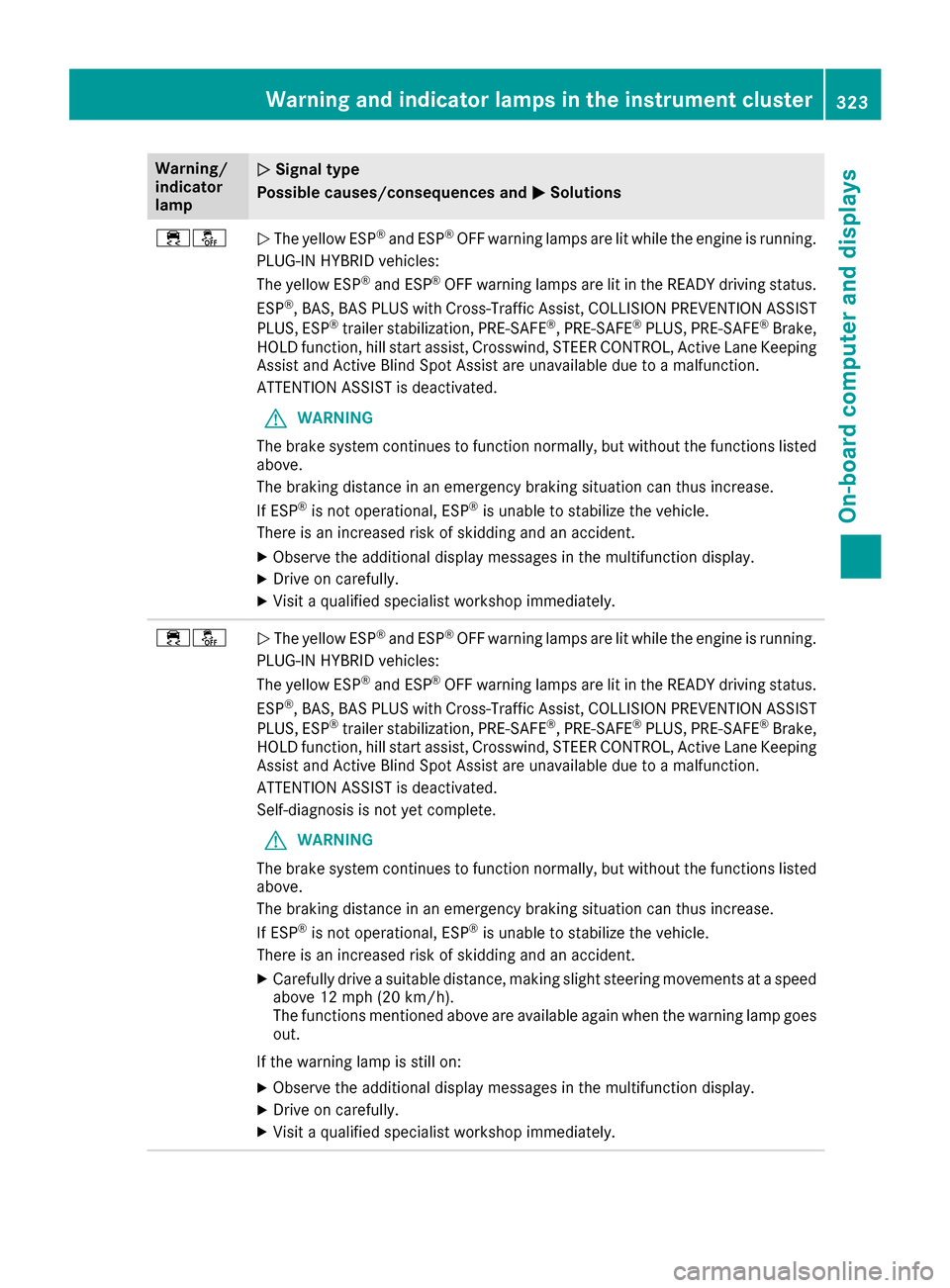
÷åNThe yellow ESP®and ESP®OFF warning lamps are lit while the engine is running.
PLUG-IN HYBRID vehicles:
The yellow ESP
®and ESP®OFF warning lamps are lit in the READY driving status.
ESP®, BAS, BAS PLUS with Cross-Traffic Assist, COLLISION PREVENTION ASSIST
PLUS, ESP®trailer stabilization, PRE‑ SAFE®, PRE‑SAFE®PLUS, PRE‑ SAFE®Brake,
HOLD function, hill start assist, Crosswind, STEER CONTROL, Active Lane Keeping
Assist and Active Blind Spot Assist are unavailable due to a malfunction.
ATTENTION ASSIST is deactivated.
GWARNING
The brake system continues to function normally, but without the functions listed
above.
The braking distance in an emergency braking situation can thus increase.
If ESP
®is not operational, ESP®is unable to stabilize the vehicle.
There is an increased risk of skidding and an accident.
XObserve the additional display messages in the multifunction display.
XDrive on carefully.
XVisit a qualified specialist workshop immediately.
÷åN The yellow ESP®and ESP®OFF warning lamps are lit while the engine is running.
PLUG-IN HYBRID vehicles:
The yellow ESP
®and ESP®OFF warning lamps are lit in the READY driving status.
ESP®, BAS, BAS PLUS with Cross-Traffic Assist, COLLISION PREVENTION ASSIST
PLUS, ESP®trailer stabilization, PRE‑ SAFE®, PRE‑SAFE®PLUS, PRE‑ SAFE®Brake,
HOLD function, hill start assist, Crosswind, STEER CONTROL, Active Lane Keeping
Assist and Active Blind Spot Assist are unavailable due to a malfunction.
ATTENTION ASSIST is deactivated.
Self-diagnosis is not yet complete.
GWARNING
The brake system continues to function normally, but without the functions listed
above.
The braking distance in an emergency braking situation can thus increase.
If ESP
®is not operational, ESP®is unable to stabilize the vehicle.
There is an increased risk of skidding and an accident.
XCarefully drive a suitable distance, making slight steering movements at a speed
above 12 mph (20 km/h).
The functions mentioned above are available again when the warning lamp goes
out.
If the warning lamp is still on:
XObserve the additional display messages in the multifunction display.
XDrive on carefully.
XVisit a qualified specialist workshop immediately.
Warning and indicator lamps in the instrument cluster323
On-board computer and displays
Z
Page 368 of 450

Cleaning the 360° camera
!Do not clean the camera lens and the area
around the 360° camera with a power
washer.360
XMake sure that the vehicle is stationary and
that the SmartKey is in position 2in the igni-
tion lock.
XOpen the camera cover for cleaning via the
multimedia system (see separate operating
instructions).
XTo clean the rear view camera: use clean
water and a soft cloth to clean camera
lens :.
Cleaning the exhaust pipe
GWARNING
The exhaust tail pipe and tail pipe trim can
become very hot. If you come into contact
with these parts of the vehicle, you could burn
yourself. There is a risk of injury.
Always be particularly careful around the
exhaust tail pipe and the tail pipe trim. Allow
these components to cool down before touch-
ing them.
!Mercedes-AMG GLE 63 vehicles with black
exhaust pipes: black chromed exhaust tips
should not be polished with a chrome polish. They will otherwise lose their black shine. For
optimal care, the faceplates should be rubbed with a lightly oiled cloth after every car wash.
Commercially available engine and care oils
are suitable for this.
For heavier soiling, you can apply a fine paint-
work polish with a microfiber cloth. Remove
the excess polish residue after polishing. Impurities combined with the effects of road grit
and corrosive environmental factors may cause
flash rust to form on the surface. You can
restore the original shine of the exhaust pipe by
cleaning it regularly, especially in winter and
after washing.
XClean the exhaust pipe with a chrome care
product tested and approved by Mercedes-
Benz.
Cleaning the trailer tow hitch
HEnvironmental note
Dispose of rags soaked in oil and grease in an
environmentally responsible manner.
!Do not clean the ball coupling with a power
washer. Do not use solvents.
!Please note the care instructions in the
trailer coupling manufacturer's operating
instructions.
The ball coupling must be cleaned if it becomes
dirty or corroded.
XRemove rust on the ball of the ball coupling,
e.g. with a wire brush.
XRemove dirt with a clean, lint-free cloth or a
brush.
XAfter cleaning, lightly oil or grease ball cou-
pling :.
XCheck that the vehicle's trailer tow hitch is
working properly.
iYou can also have the maintenance work on
the ball coupling and the trailer tow hitch car-
ried out by a qualified specialist workshop.
366Care
Maintenance and care
Page 383 of 450

XStart the engine of the donor vehicle and run it at idling speed.
XConnect negative terminal?of donor battery Bto ground point Aof your vehicle using the
jumper cable, connecting the jumper cable to battery of other vehicle Bfirst.
XStart the engine.
XBefore disconnecting the jumper cables, let the engine run for several minutes.
XFirst, remove the jumper cables from ground point Aand negative terminal ?, then from pos-
itive clamp ;and positive terminal =. Begin each time at the contacts on your own vehicle first.
XClose cover:of positive terminal ;after removing the jumper cables.
XHave the battery checked at a qualified specialist workshop.
PLUG-IN HYBRID vehicles: if your vehicle has been jump-started, it may not be possible to use the
electric drive for approximately 30 minutes.
Jump-starting is not considered to be a normal operating condition.
iJumper cables and further information regarding jump-starting can be obtained at any qualified
specialist workshop.
Towing and tow-starting
Important safety notes
GWARNING
Functions relevant to safety are restricted or
no longer available if:
Rthe engine is not running.
Rthe brake system or the power steering is
malfunctioning.
Rthere is a malfunction in the voltage supply or the vehicle's electrical system.
If your vehicle is being towed, much more
force may be necessary to steer or brake.
There is a risk of an accident.
In such cases, use a tow bar. Before towing,
make sure that the steering moves freely.
GWARNING
When towing or tow-starting another vehicle
and its weight is greater than the permissible
gross weight of your vehicle, the:
Rthe towing eye could detach itself
Rthe vehicle/trailer combination could roll-
over.
There is a risk of an accident.
When towing or tow-starting another vehicle,
its weight should not be greater than the per- missible gross weight of your vehicle. Details on the permissible gross vehicle weight
of your vehicle can be found on the vehicle iden-
tification plate (
Ypage 432).
!When COLLISION PREVENTION ASSIST
PLUS, DISTRONIC PLUS or the HOLD function
is activated, the vehicle brakes automatically
in certain situations.
To avoid damage to the vehicle, deactivate
these systems in the following or similar sit-
uations:
Rwhen towing the vehicle
Rin the car wash
!Make sure that the electric parking brake is
released. If the electric parking brake is faulty,
visit a qualified specialist workshop.
!Only secure the tow rope or tow bar at the
towing eyes, or the trailer tow hitch, if availa-
ble. You could otherwise damage the vehicle.
!Do not use the trailer tow hitch for recovery
or towing. Do not use the towing eye for
recovery. this could damage the vehicle. If in
doubt, have the vehicle recovere d u
sing a
crane.
!When towing, pull away slowly and
smoothly. Pull the towed vehicle as straight as
possible and not at an acute angle. Excessive
tractive power could damage the vehicles.
When towing, it is preferable to use a rigid tow-
ing bar as opposed to a tow rope. A rigid towing
bar helps to keep the tractive power low.
!When towing vehicles with KEYLESS-GO,
use the key instead of the Start/Stop button.
Towing and tow-starting381
Breakdown assitance
Z
Page 384 of 450
Otherwise, the automatic transmission may
shift to positionPwhen the driver's or front-
passenger door are opened, which could lead
to damage to the transmission.
!Do not tow with sling-type equipment. This
could damage the vehicle.
!Vehicles with differential locks: make sure
the differential locks are in automatic mode.
When towing, the differential locks must not
be switched on. The transmission may other- wise be damaged.
!The vehicle can be towed a maximum of
30 miles (50km). The towing speed of 30 mph
(50 km/h) must not be exceeded.
If the vehicle has to be towed more than
30 miles (50km), the entire vehicle must be
raised and transported.
It is better to have the vehicle transported than
to have it towed away.
If the vehicle has suffered transmission damage,
have it transported on a transporter or trailer.
The automatic transmission must be in position
N when the vehicle is being towed.
The battery must be connected and charged.
Otherwise, you:
Rcannot turn the SmartKey to position 2in the
ignition lock
Rcannot release the electric parking brake
Rcannot shift the automatic transmission to
position N
Disarm the automatic locking feature before the vehicle is towed (
Ypage 275). You could other-
wise be locked out when pushing or towing the
vehicle.
PLUG-IN HYBRID vehicles:
PLUG-IN HYBRID vehicles may not be towed
away but must instead be transported, if:
Rthe multifunction display is not working or
Rthe á Towing Not Permitted SeeOperator'sManualmessage appears in the
multifunction display.
If the vehicle is in a dangerous area, it can be
towed out of that area with both axles on the
ground. In this case, the towing distance must
not be greater than 165 ft (50 m)and must not
exceed a towing speed of 6 mph (10 km/h). For
longer distances, have the vehicle loaded and
transported.
Installing/removing the towing eye
Installing the towing eye
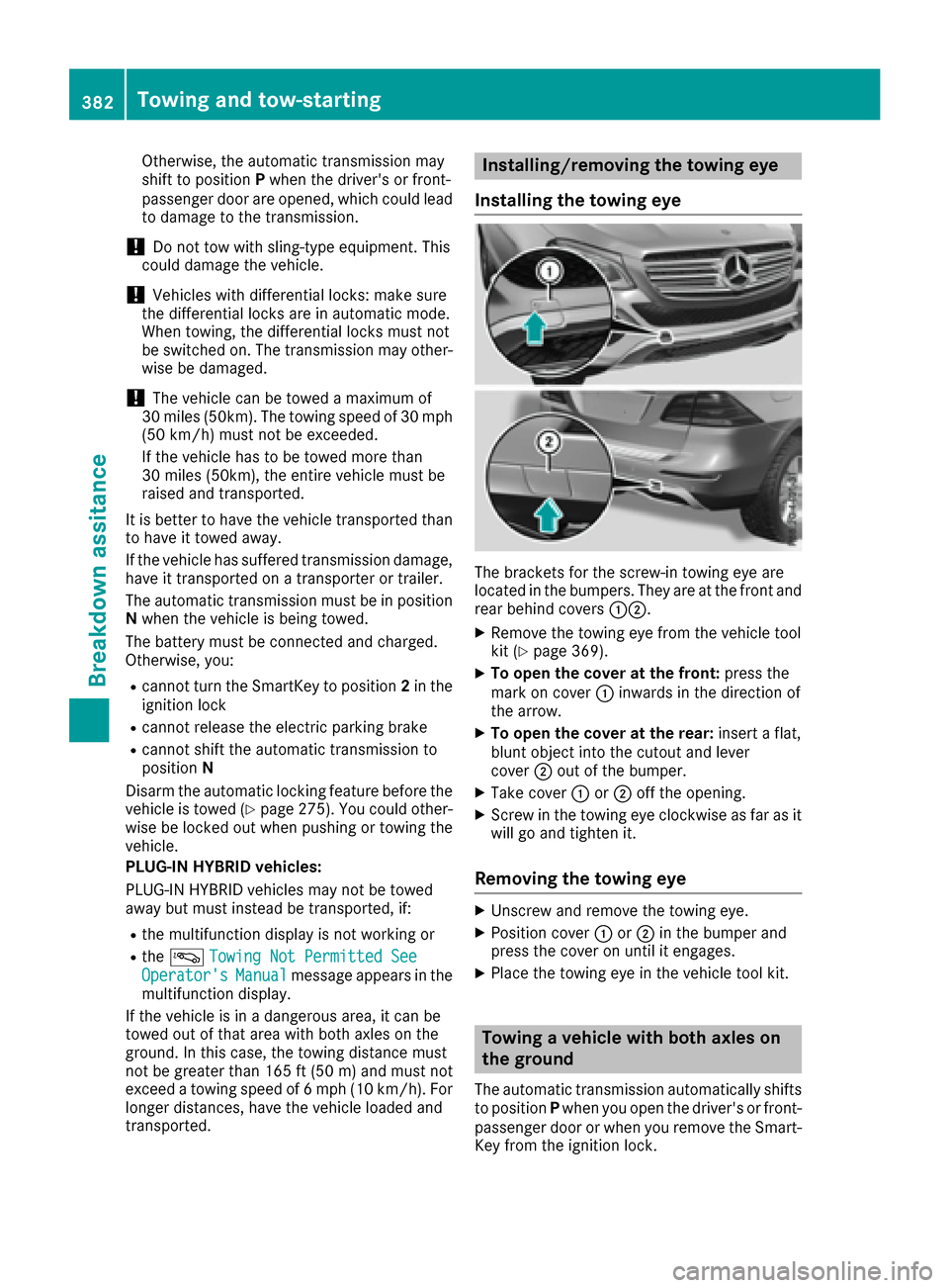
The brackets for the screw-in towing eye are
located in the bumpers. They are at the front and
rear behind covers :;.
XRemove the towing eye from the vehicle tool
kit (Ypage 369).
XTo open the cover at the front: press the
mark on cover :inwards in the direction of
the arrow.
XTo open the cover at the rear: insert a flat,
blunt object into the cutout and lever
cover ;out of the bumper.
XTake cover :or; off the opening.
XScrew in the towing eye clockwise as far as it
will go and tighten it.
Removing the towing eye
XUnscrew and remove the towing eye.
XPosition cover :or; in the bumper and
press the cover on until it engages.
XPlace the towing eye in the vehicle tool kit.
Towing a vehicle with both axles on
the ground
The automatic transmission automatically shifts
to position Pwhen you open the driver's or front-
passenger door or when you remove the Smart-
Key from the ignition lock.
382Towing and tow-starting
Breakdown assitance
Page 385 of 450

In order to ensure that the automatic transmis-
sion stays in positionNwhen towing the vehicle,
you must observe the following points:
XMake sure that the vehicle is stationary.
XTurn the SmartKey to position 2in the ignition
lock.
XDepress and hold the brake pedal.
XShift the automatic transmission to position
N.
XLeave the SmartKey in position 2in the igni-
tion lock.
XRelease the brake pedal.
XRelease the electric parking brake.
XSwitch on the hazard warning lamps
(Ypage 116).
In order to signal a change of direction when
towing the vehicle with the hazard warning
lamps switched on, use the combination switch
as usual. In this case, only the indicator lamps
for the direction of travel flash. After resetting
the combination switch, the hazard warning
lamp starts flashing again.
Transporting the vehicle
PLUG-IN HYBRID vehicles
Transportation of the vehicle should only be car-
ried out by professional recovery companies.
4MATIC vehicles/vehicles with auto-
matic transmission
!When the vehicle is loaded for transport, the
front and rear axles must be stationary and on
the same transportation vehicle. Positioning
over the connection point of the transport
vehicle is not permitted. The drive train may
otherwise be damaged.
All vehicles
!You may only secure the vehicle by the
wheels, not by parts of the vehicle such as
axle or steering components. Otherwise, the
vehicle could be damaged.
The towing eye can be used to pull the vehicle
onto a trailer or transporter for transporting pur-
poses.
XTurn the SmartKey to position 2in the ignition
lock.
XShift the automatic transmission to position
N.
As soon as the vehicle has been loaded:
XPrevent the vehicle from rolling away by
applying the electric parking brake.
XShift the automatic transmission to posi-
tion P.
XTurn the SmartKey to position 0in the ignition
lock and remove it.
XSecure the vehicle.
Information on 4MATIC vehicles
!
Vehicles with 4MATIC must not be towed
with either the front or the rear axle raised, as
doing so will damage the transmission.
Vehicles with 4MATIC may either be towed away with both axles on the ground or be loaded up
and transported.
If the vehicle's transmission, front, or rear axle is
damaged, have the vehicle transported on a
truck or trailer.
In the event of damage to the electrical sys-
tem: if the battery is defective, the automatic
transmission will be locked in position P. To shift
the automatic transmission to position N, you
must provide power to the vehicle's electrical
system in the same way as when jump-starting
(
Ypage 379).
Have the vehicle transported on a transporter or
trailer.
Tow-starting (emergency engine
starting)
!
Vehicles with automatic transmission must
not be tow-started. You could otherwise dam-
age the automatic transmission.
Towing and tow-starting383
Breakdown assitance
Z
Page 393 of 450
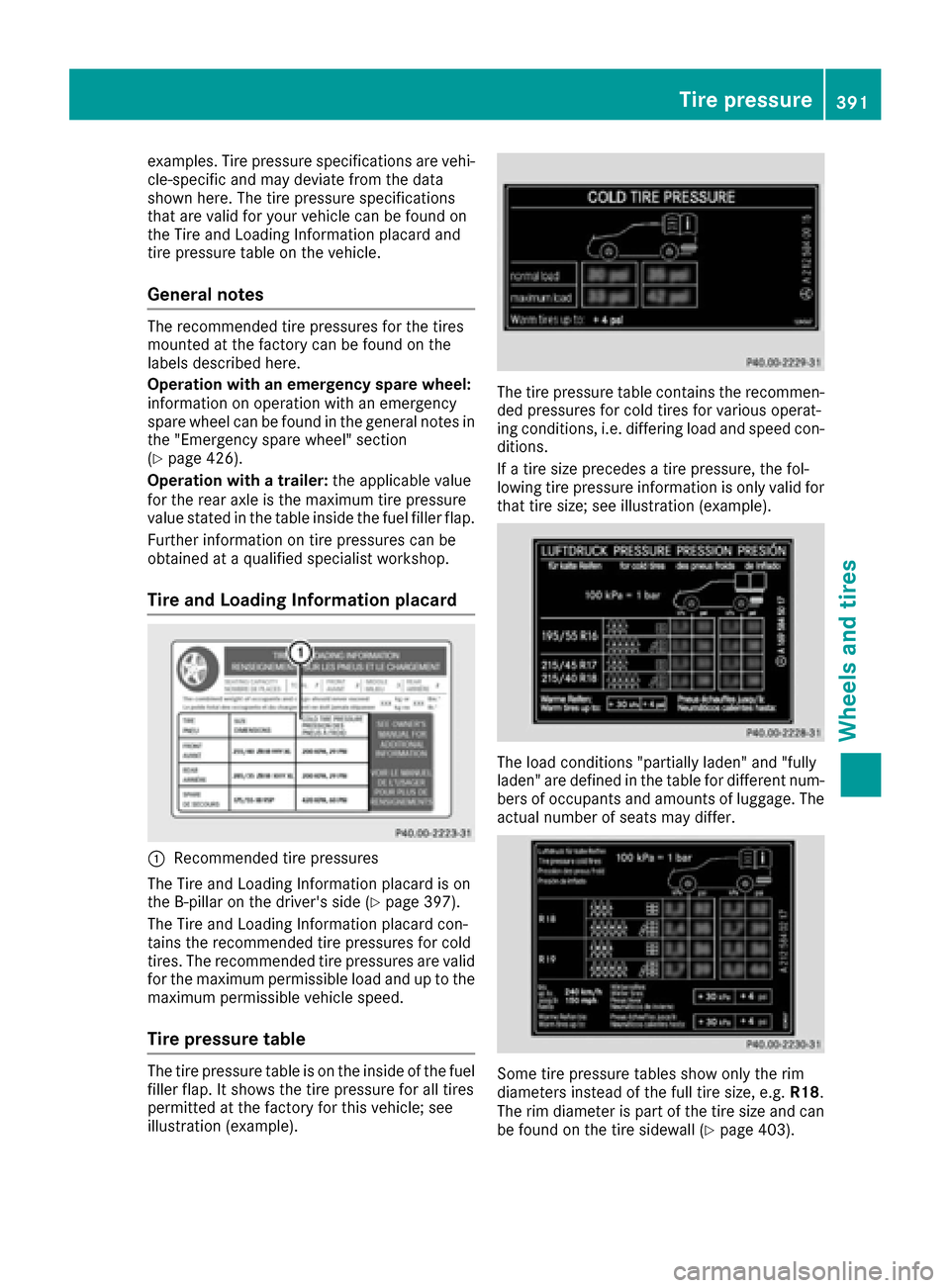
examples. Tire pressure specifications are vehi-
cle-specific and may deviate from the data
shown here. The tire pressure specifications
that are valid for your vehicle can be found on
the Tire and Loading Information placard and
tire pressure table on the vehicle.
General notes
The recommended tire pressures for the tires
mounted at the factory can be found on the
labels described here.
Operation with an emergency spare wheel:
information on operation with an emergency
spare wheel can be found in the general notes in
the "Emergency spare wheel" section
(
Ypage 426).
Operation with a trailer: the applicable value
for the rear axle is the maximum tire pressure
value stated in the table inside the fuel filler flap.
Further information on tire pressures can be
obtained at a qualified specialist workshop.
Tire and Loading Information placard
:Recommended tire pressures
The Tire and Loading Information placard is on
the B-pillar on the driver's side (
Ypage 397).
The Tire and Loading Information placard con-
tains the recommended tire pressures for cold
tires. The recommended tire pressures are valid
for the maximum permissible load and up to the
maximum permissible vehicle speed.
Tire pressure table
The tire pressure table is on the inside of the fuel
filler flap. It shows the tire pressure for all tires
permitted at the factory for this vehicle; see
illustration (example).
The tire pressure table contains the recommen-
ded pressures for cold tires for various operat-
ing conditions, i.e. differing load and speed con-
ditions.
If a tire size precedes a tire pressure, the fol-
lowing tire pressure information is only valid for that tire size; see illustration (example).
The load conditions "partially laden" and "fully
laden" are defined in the table for different num-
bers of occupants and amounts of luggage. The
actual number of seats may differ.
Some tire pressure tables show only the rim
diameters instead of the full tire size, e.g. R18.
The rim diameter is part of the tire size and can
be found on the tire sidewall (
Ypage 403).
Tire pressure391
Wheels and tires
Z
Page 402 of 450
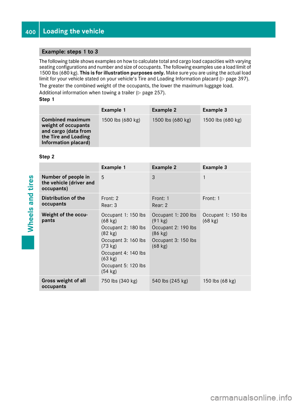
Example: steps 1 to 3
The following table shows examples on how to calculate total and cargo load capacities with varying
seating configurations and number and size of occupants. The following examples use a load limit of
1500 lbs (680 kg).This is for illustration purposes only. Make sure you are using the actual load
limit for your vehicle stated on your vehicle's Tire and Loading Information placard (
Ypage 397).
The greater the combined weight of the occupants, the lower the maximum luggage load.
Additional information when towing a trailer (
Ypage 257).
Step 1
Example 1Example 2Example 3
Combined maximum
weight of occupants
and cargo (data from
the Tire and Loading
Information placard)1500 lbs (680 kg)1500 lbs (680 kg)1500 lbs (680 kg)
Step 2
Example 1Example 2Example 3
Number of people in
the vehicle (driver and
occupants)531
Distribution of the
occupantsFront: 2
Rear: 3Front: 1
Rear: 2Front: 1
Weight of the occu-
pantsOccupant 1: 150 lbs
(68 kg)
Occupant 2: 180 lbs
(82 kg)
Occupant 3: 160 lbs
(73 kg)
Occupant 4: 140 lbs
(63 kg)
Occupant 5: 120 lbs
(54 kg)Occupant 1: 200 lbs
(91 kg)
Occupant 2: 190 lbs
(86 kg)
Occupant 3: 150 lbs
(68 kg)Occupant 1: 150 lbs
(68 kg)
Gross weight of all
occupants750 lbs (340 kg)540 lbs (245 kg)150 lbs (68 kg)
400Loading the vehicle
Wheels and tires
Page 403 of 450
Step 3
Example 1Example 2Example 3
Permissible load (maxi-
mum gross vehicle
weight rating from the
Tire and Loading Infor-
mation placard minus
the gross weight of all
occupants)1500 lbs (680 kg)Ò
750 lbs (340 kg) =
750 lbs (340 kg)1500 lbs (680 kg) Ò
540 lbs (245 kg)
=960 lbs (435 kg)1500 lbs (680 kg) Ò
150 lbs (68 kg) =
1350 lbs (612 kg)
Vehicle identification plate
Even if you have calculated the total cargo care-
fully, you should still make sure that the gross
vehicle weight rating and the gross axle weight
rating are not exceeded. Details can be found on
the vehicle identification plate on the B-pillar on
the driver's side of the vehicle (
Ypage 397).
Permissible Gross Vehicle Weight Rating
(GVWR): the gross weight of the vehicle, all pas-
sengers, load and trailer load/noseweight (if
applicable) must not exceed the permissible
gross vehicle weight.
Gross Axle Weight Rating (GAWR): the maxi-
mum permissible weight that can be carried by
one axle (front or rear axle).
To ensure that your vehicle does not exceed the
maximum permissible values (gross vehicle
weight and maximum gross axle weight rating),
have your loaded vehicle (including driver, occu-
pants, cargo, and full trailer load if applicable)
weighed on a suitable vehicle weighbridge.
Trailer load/noseweight
The trailer load/noseweight affects the gross
weight of the vehicle. If a trailer is attached, the trailer load/noseweight is included in the load
along with occupants and luggage. The trailer
load/noseweight is usually approximately 8% of
the gross weight of the trailer and its cargo.
All about wheels and tires
Uniform Tire Quality Grading Stand-
ards
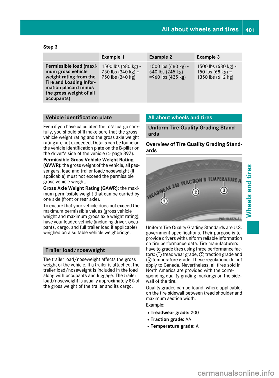
Overview of Tire Quality Grading Stand-
ards
Uniform Tire Quality Grading Standards are U.S.
government specifications. Their purpose is to
provide drivers with uniform reliable information on tire performance data. Tire manufacturers
have to grade tires using three performance fac-
tors: :tread wear grade, ;traction grade and
= temperature grade. These regulations do not
apply to Canada. Nevertheless, all tires sold in
North America are provided with the corre-
sponding quality grading markings on the side-
wall of the tire.
Quality grades can be found, where applicable,
on the tire sidewall between tread shoulder and
maximum section width.
Example:
RTreadwear grade: 200
RTraction grade:AA
RTemperature grade: A
All about wheels and tires401
Wheels and tires
Z