2016 MERCEDES-BENZ GLE-Class tailgate
[x] Cancel search: tailgatePage 340 of 450

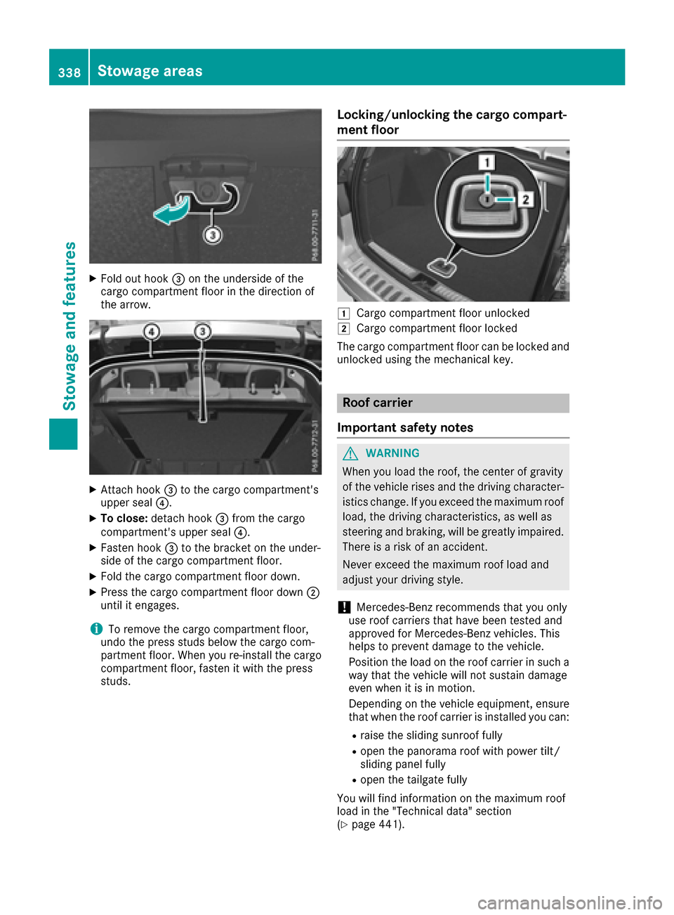
XFold out hook=on the underside of the
cargo compartment floor in the direction of
the arrow.
XAttach hook =to the cargo compartment's
upper seal ?.
XTo close:detach hook =from the cargo
compartment's upper seal ?.
XFasten hook=to the bracket on the under-
side of the cargo compartment floor.
XFold the cargo compartment floor down.
XPress the cargo compartment floor down ;
until it engages.
iTo remove the cargo compartment floor,
undo the press studs below the cargo com-
partment floor. When you re-install the cargo
compartment floor, fasten it with the press
studs.
Locking/unlocking the cargo compart-
ment floor
1Cargo compartment floor unlocked
2Cargo compartment floor locked
The cargo compartment floor can be locked and
unlocked using the mechanical key.
Roof carrier
Important safety notes
GWARNING
When you load the roof, the center of gravity
of the vehicle rises and the driving character-
istics change. If you exceed the maximum roof
load, the driving characteristics, as well as
steering and braking, will be greatly impaired.
There is a risk of an accident.
Never exceed the maximum roof load and
adjust your driving style.
!Mercedes-Benz recommends that you only
use roof carriers that have been tested and
approved for Mercedes-Benz vehicles. This
helps to prevent damage to the vehicle.
Position the load on the roof carrier in such a
way that the vehicle will not sustain damage
even when it is in motion.
Depending on the vehicle equipment, ensure
that when the roof carrier is installed you can:
Rraise the sliding sunroof fully
Ropen the panorama roof with power tilt/
sliding panel fully
Ropen the tailgate fully
You will find information on the maximum roof
load in the "Technical data" section
(
Ypage 441).
338Stowage areas
Stowage and features
Page 371 of 450

Useful information
i
This Operator's Manual describes all models
and all standard and optional equipment of
your vehicle available at the time of publica-
tion of the Operator's Manual. Country-spe-
cific differences are possible. Please note
that your vehicle may not be equipped with all
features described. This also applies to
safety-related systems and functions.
iRead the information on qualified specialist
workshops (Ypage 29).
Where will I find...?
Vehicle tool kit
General notes
The vehicle tool kit can be found in the stowage
well under the cargo compartment floor.
Apart from certain country-specific variations,
the vehicles are not equipped with a tire-change
tool kit. Some tools for changing a wheel are
specific to the vehicle. For more information on which tools are required to perform a wheel
change on your vehicle, consult a qualified spe-
cialist workshop.
Tools required for changing a wheel may
include, for example:
RJack
RWheel chock
RLug wrench
RRatchet wrench
RAlignment bolt
Vehicles with a TIREFIT kit
:Jack
;Folding wheel chock
=Towing eye
?Alignment bolt
ATire inflation compressor
BLug wrench
CRatchet wrench
DTire sealant filler bottle
XOpen the tailgate.
XLift the cargo compartment floor upwards
(Ypage 337).
XUse the TIREFIT kit (Ypage 371).
Vehicles with a "Minispare" emergency
spare wheel
:Folding wheel chock
;Lug wrench
=Alignment bolt
?Towing eye
AJack
BRatchet wrench
Where will I find...?369
Breakdown assitance
Page 372 of 450

XOpen the tailgate.
XLift the cargo compartment floor upwards
(Ypage 337).
XRemove the "Minispare" emergency spare
wheel (Ypage 427).
Flat tire
Preparing the vehicle
Your vehicle may be equipped with:
RMOExtended tires (tires with run-flat proper-
ties)
Vehicle preparation is not necessary on vehi-
cles with MOExtended tires
Ra TIREFIT kit (Ypage 369)
Ran emergency spare wheel (only for certain
countries)
Information on changing and mounting wheels
(
Ypage 408).
XStop the vehicle on solid, non-slippery and
level ground, as far away as possible from
traffic.
XSwitch on the hazard warning lamps.
XSecure the vehicle against rolling away
(Ypage 178).
XIf possible, bring the front wheels into the
straight-ahead position.
XVehicles with the AIRMATIC package:
make sure that the normal vehicle level is
selected (
Ypage 207).
XVehicles with the Off-Road Engineering
package: make sure that the normal vehicle
level is selected (
Ypage 201).
XSwitch off the engine.
XVehicles without KEYLESS-GO: remove the
SmartKey from the ignition lock.
XVehicles with KEYLESS-GO: open the driv-
er's door.
The on-board electronics now have status 0.
This is the same as the SmartKey having been
removed.
XVehicles with KEYLESS-GO: remove the
Start/Stop button from the ignition lock
(
Ypage 146).
XMake sure that the engine cannot be started
via your smartphone (Ypage 148).
XMake sure that the passengers are not endan-
gered as they do so. Make sure that no one is
near the danger area while a wheel is being changed. Anyone who is not directly assisting
in the wheel change should, for example,
stand behind the barrier.
XGet out of the vehicle. Pay attention to traffic
conditions when doing so.
XClose the driver's door.
XUnload heavy luggage.
iOnly operate the tire inflation compressor
using a 12 V socket, even if the ignition is
turned off (
Ypage 343).
An emergency cut-out ensures that the on-
board voltage does not drop too low. If the on-
board voltage is too low, the power to the
sockets is automatically cut. This ensures
that there is sufficient power to start the
engine.
MOExtended tires (tires with run-flat
properties)
General notes
With MOExtended tires (tires with run flat char-
acteristics), you can continue to drive your vehi-
cle even if there is a total loss of pressure in one
or more tires. The affected tire must not show
any clearly visible damage.
You can recognize MOExtended tires by the
MOExtended marking which appears on the
sidewall of the tire. You will find this marking
next to the tire size designation, the load-bear-
ing capacity and the speed index (
Ypage 403).
MOExtended tires may only be used in conjunc-
tion with an active tire pressure loss warning
system or with an active tire pressure monitor.
If a pressure loss warning message appears
in the multifunction display:
Robserve the instructions in the display mes-
sages (Ypage 309).
Rcheck the tire for damage.
Rif driving on, observe the following notes.
The driving distance possible in run-flat mode is
approximately 50 miles (80 km) when the vehi-
cle is partially laden and approximately 18 miles
(30 km) when the vehicle is fully laden.
In addition to the vehicle load, the driving dis-
tance possible depends upon:
Rvehicle speed
Rroad condition
Routside temperature
370Flat tire
Breakdown assitance
Page 412 of 450

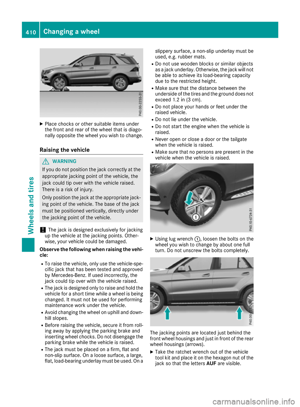
XPlace chocks or other suitable items under
the front and rear of the wheel that is diago-
nally opposite the wheel you wish to change.
Raising the vehicle
GWARNING
If you do not position the jack correctly at the
appropriate jacking point of the vehicle, the
jack could tip over with the vehicle raised.
There is a risk of injury.
Only position the jack at the appropriate jack-
ing point of the vehicle. The base of the jack
must be positioned vertically, directly under
the jacking point of the vehicle.
!The jack is designed exclusively for jacking
up the vehicle at the jacking points. Other-
wise, your vehicle could be damaged.
Observe the following when raising the vehi-
cle:
RTo raise the vehicle, only use the vehicle-spe-
cific jack that has been tested and approved
by Mercedes-Benz. If used incorrectly, the
jack could tip over with the vehicle raised.
RThe jack is designed only to raise and hold the
vehicle for a short time while a wheel is being
changed. It must not be used for performing
maintenance work under the vehicle.
RAvoid changing the wheel on uphill and down-
hill slopes.
RBefore raising the vehicle, secure it from roll-
ing away by applying the parking brake and
inserting wheel chocks. Do not disengage the
parking brake while the vehicle is raised.
RThe jack must be placed on a firm, flat and
non-slip surface. On a loose surface, a large,
flat, load-bearing underlay must be used. On a slippery surface, a non-slip underlay must be
used, e.g. rubber mats.
RDo not use wooden blocks or similar objects
as a jack underlay. Otherwise, the jack will not
be able to achieve its load-bearing capacity
due to the restricted height.
RMake sure that the distance between the
underside of the tires and the ground does not
exceed 1.2 in (3 cm).
RDo not place your hands or feet under the
raised vehicle.
RDo not lie under the vehicle.
RDo not start the engine when the vehicle is
raised.
RNever open or close a door or the tailgate
when the vehicle is raised.
RMake sure that no persons are present in the
vehicle when the vehicle is raised.
XUsing lug wrench :, loosen the bolts on the
wheel you wish to change by about one full
turn. Do not unscrew the bolts completely.
The jacking points are located just behind the
front wheel housings and just in front of the rear
wheel housings (arrows).
XTake the ratchet wrench out of the vehicle
tool kit and place it on the hexagon nut of the
jack so that the letters AUFare visible.
410Changing a wheel
Wheels and tires