2016 MERCEDES-BENZ GLE-CLASS COUPE towing
[x] Cancel search: towingPage 329 of 382
In order to ensure that the automatic transmis-
sion stays in positionNwhen towing the vehicle,
you must observe the following points:
XMake sure that the vehicle is stationary.
XTurn the SmartKey to position 2in the ignition
lock.
XDepress and hold the brake pedal.
XShift the automatic transmission to position
N.
XLeave the SmartKey in position 2in the igni-
tion lock.
XRelease the brake pedal.
XRelease the electric parking brake.
XSwitch on the hazard warning lamps
(Ypage 110).
In order to signal a change of direction when
towing the vehicle with the hazard warning
lamps switched on, use the combination switch
as usual. In this case, only the indicator lamps
for the direction of travel flash. After resetting
the combination switch, the hazard warning
lamp starts flashing again.
Transporting the vehicle
4MATIC vehicles/vehicles with auto-
matic transmission
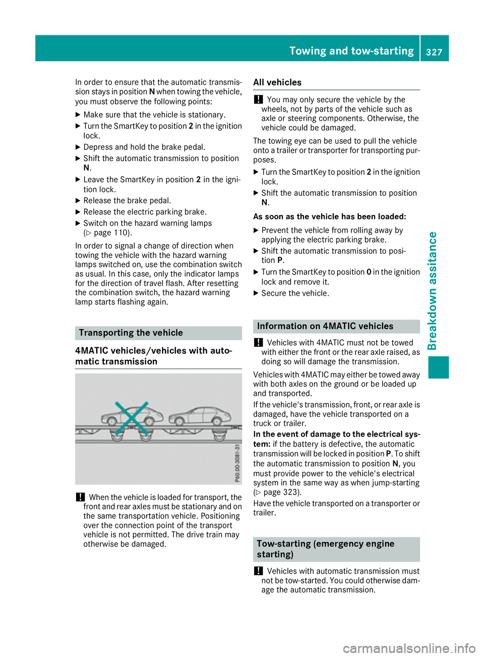
!When the vehicle is loaded for transport, the
front and rear axles must be stationary and on the same transportation vehicle. Positioning
over the connection point of the transport
vehicle is not permitted. The drive train may
otherwise be damaged.
All vehicles
!You may only secure the vehicle by the
wheels, not by parts of the vehicle such as
axle or steering components. Otherwise, the
vehicle could be damaged.
The towing eye can be used to pull the vehicle
onto a trailer or transporter for transporting pur-
poses.
XTurn the SmartKey to position 2in the ignition
lock.
XShift the automatic transmission to position
N.
As soon as the vehicle has been loaded:
XPrevent the vehicle from rolling away by
applying the electric parking brake.
XShift the automatic transmission to posi-
tion P.
XTurn the SmartKey to position 0in the ignition
lock and remove it.
XSecure the vehicle.
Information on 4MATIC vehicles
!
Vehicles with 4MATIC must not be towed
with either the front or the rear axle raised, as
doing so will damage the transmission.
Vehicles with 4MATIC may either be towed away with both axles on the ground or be loaded up
and transported.
If the vehicle's transmission, front, or rear axle is
damaged, have the vehicle transported on a
truck or trailer.
In the event of damage to the electrical sys-
tem: if the battery is defective, the automatic
transmission will be locked in position P. To shift
the automatic transmission to position N, you
must provide power to the vehicle's electrical
system in the same way as when jump-starting
(
Ypage 323).
Have the vehicle transported on a transporter or
trailer.
Tow-starting (emergency engine
starting)
!
Vehicles with automatic transmission must
not be tow-started. You could otherwise dam-
age the automatic transmission.
Towing and tow-starting327
Breakdown assitance
Z
Page 345 of 382
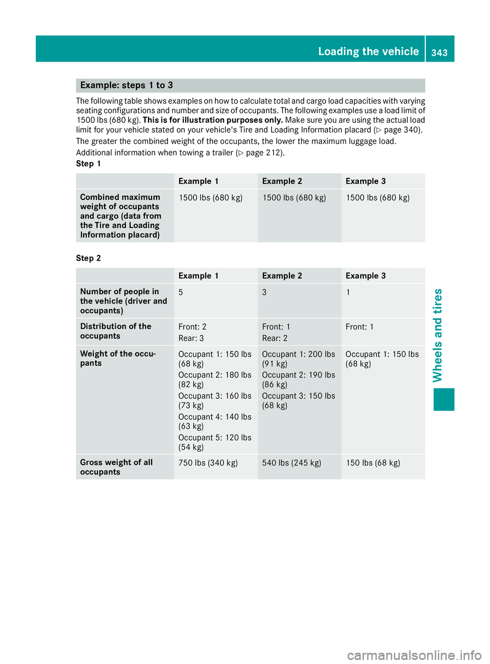
Example: steps 1 to 3
The following table shows examples on how to calculate total and cargo load capacities with varying
seating configurations and number and size of occupants. The following examples use a load limit of
1500 lbs (680 kg).This is for illustration purposes only. Make sure you are using the actual load
limit for your vehicle stated on your vehicle's Tire and Loading Information placard (
Ypage 340).
The greater the combined weight of the occupants, the lower the maximum luggage load.
Additional information when towing a trailer (
Ypage 212).
Step 1
Example 1Example 2Example 3
Combined maximum
weight of occupants
and cargo (data from
the Tire and Loading
Information placard)1500 lbs (680 kg)1500 lbs (680 kg)1500 lbs (680 kg)
Step 2
Example 1Example 2Example 3
Number of people in
the vehicle (driver and
occupants)531
Distribution of the
occupantsFront: 2
Rear: 3Front: 1
Rear: 2Front: 1
Weight of the occu-
pantsOccupant 1: 150 lbs
(68 kg)
Occupant 2: 180 lbs
(82 kg)
Occupant 3: 160 lbs
(73 kg)
Occupant 4: 140 lbs
(63 kg)
Occupant 5: 120 lbs
(54 kg)Occupant 1: 200 lbs
(91 kg)
Occupant 2: 190 lbs
(86 kg)
Occupant 3: 150 lbs
(68 kg)Occupant 1: 150 lbs
(68 kg)
Gross weight of all
occupants750 lbs (340 kg)540 lbs (245 kg)150 lbs (68 kg)
Loading the vehicle343
Wheels and tires
Z
Page 363 of 382

Replaceth etires after six years at th elatest ,
regardless of wear .This also applie sto th e
emergenc yspar ewheel.
iWhen you are driving wit hth ecollapsible
spar ewhee lmounted, th etire pressur eloss
warning system or th etire pressur emonitor
canno tfunction reliably. Only restar tth etire
pressur eloss warning system or tire pressur e
monitor when th edefective whee lhas been
replace dwit h a newwheel.
Vehicles with tire pressure monitor: after
mounting an emergenc yspar ewheel, th esys-
te m may still display th etire pressur eof th e
remove dwhee lfor afew minutes. The value
displayed for th emounte demergenc yspar e
whee lis no tth esam eas th ecurren ttire pres-
sur eof th eemergenc yspar ewheel.
Removing/stowing the emergency
spare wheel
Vehicles with a "Minispare" emergency
spare wheel under the cargo compart-
ment floor
Always observ eth einstruction sand safet y
note sin th e"Mounting awheel" section
(
Ypage 352).
The "Minispare" emergenc yspar ewhee lcan be
foun din th estowage well under th ecargo com-
partmen tfloor.
Removin gth eemergenc yspar ewhee l
XLiftth ecargo compartmen tfloor upwards
(Ypage 284).
XTurn retaining screw ;counter-clockwise
and remove it .
XRemove "Minispare" emergenc yspar e
whee l:.
Vehicles with a "Minispare" emergency
spare wheel in the emergency spare
wheel bag
Always observ eth einstruction sand safet y
note sin th e"Mounting awheel" section
(
Ypage 352).
On vehicles wit h aBan g & Olufsen soun dsys-
tem, th e"Minispare" emergenc yspar ewhee lis
packe din an emergenc yspar ewhee lbag. The
emergenc yspar ewhee lbag is secured to th e
cargo tie-down rings in th ecargo compartment.
Removin gth eemergenc yspar ewhee l
XDetac hfastenin gstraps ;.
XUnhookretaining spring hooks :and =of
fastenin gstraps ;from th ecargo tie-down
rings.
XRemove th eemergenc yspar ewhee lbag wit h
th e"Minispare" emergenc yspar ewheel.
XOpen th eemergenc yspar ewhee lbag and
remove th e"Minispare" emergenc yspar e
wheel.
Stowin gth eemergenc yspar ewhee l
XPlaceth e"Minispare" emergenc yspar ewhee l
int oth eemergenc yspar ewhee lbag and
close th eemergenc yspar ewhee lbag.
XPlac eth eemergenc yspar ewhee lbag wit h
th e"Minispare" emergenc yspar ewhee lint o
th ecargo compartmen twit hth ecarryin g
strap at th eback.
XHook retaining spring hooks :and =of
fastenin gstraps ;intoth ecargo tie-down
rings.
XTighte nfastenin gstraps ;.
Emergency spare wheel361
Wheels and tires
Z
Page 364 of 382
Mercedes-AMG vehicles with a collaps-
ible spare wheel under the cargo com-
partment floor
!Only place the collapsible spare wheel in the
vehicle when it is dry. Otherwise, moisture
may get into the vehicle.
Always observe the instructions and safety
notes in the "Mounting a wheel" section
(
Ypage 352).
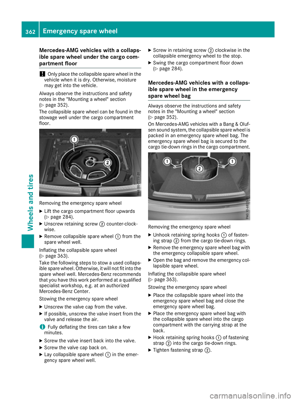
The collapsible spare wheel can be found in the
stowage well under the cargo compartment
floor.
Removing the emergency spare wheel
XLift the cargo compartment floor upwards
(Ypage 284).
XUnscrew retaining screw ;counter-clock-
wise.
XRemove collapsible spare wheel :from the
spare wheel well.
Inflating the collapsible spare wheel
(
Ypage 363).
Take the following steps to stow a used collaps- ible spare wheel. Otherwise, it will not fit into the
spare wheel well. Mercedes-Benz recommends
that you have this work performed at a qualified
specialist workshop, e.g. at an authorized
Mercedes-Benz Center.
Stowing the emergency spare wheel
XUnscrew the valve cap from the valve.
XIf possible, unscrew the valve insert from the
valve and release the air.
iFully deflating the tires can take a few
minutes.
XScrew the valve insert back into the valve.
XScrew the valve cap back on.
XLay collapsible spare wheel :in the emer-
gency spare wheel well.
XScrew in retaining screw ;clockwise in the
collapsible emergency wheel to the stop.
XSwing the cargo compartment floor down
(Ypage 284).
Mercedes-AMG vehicles with a collaps-
ible spare wheel in the emergency
spare wheel bag
Always observe the instructions and safety
notes in the "Mounting a wheel" section
(
Ypage 352).
On Mercedes-AMG vehicles with a Bang & Oluf-
sen sound system, the collapsible spare wheel is packed in an emergency spare wheel bag. The
emergency spare wheel bag is secured to the
cargo tie-down rings in the cargo compartment.
Removing the emergency spare wheel
XUnhook retaining spring hooks :of fasten-
ing strap ;from the cargo tie-down rings.
XRemove the emergency spare wheel bag with
the emergency collapsible spare wheel.
XOpen the bag and remove the emergency col-
lapsible spare wheel.
Inflating the collapsible spare wheel
(
Ypage 363).
Stowing the emergency spare wheel
XPlace the collapsible spare wheel into the
emergency spare wheel bag and close the
emergency spare wheel bag.
XPlace the emergency spare wheel bag with
the collapsible spare wheel into the cargo
compartment with the carrying strap at the
back.
XHook retaining spring hooks :of fastening
strap ;into the cargo tie-down rings.
XTighten fastening strap ;.
362Emergency spare wheel
Wheels and tires
Page 378 of 382
Vehicles with AMG bodystyling
:;
Steel-sprung vehi-
cles23°24°
Vehicles with the
AIRMATICpackage
Normal level23°24°
Raised level26°27°
For further information about approach/depar-
ture angles, see (Ypage 167).
Maximum gradient-climbing capabil-
ity
Note that the vehicle's gradient-climbing capa-
bility depends on the off-road conditions and the
road surface conditions.
The maximum gradient climbing ability is 80 %.
Accelerate carefully and make sure that the
wheels do not spin when driving on steep ter-
rain.
iIf the load on the front axle is reduced when
pulling away on a steep uphill slope, the front
wheels have a tendency to spin. 4ETS recog-
nizes this and brakes the wheels accordingly. The rear wheel torque is increased, making it
easier to drive off.
For further information about the maximum gra-
dient climbing ability, see (
Ypage 168).
Trailer tow hitch
Mounting dimensions
!
If you have a trailer tow hitch retrofitted,
changes to the cooling system and drive train
may be necessary, depending on the vehicle
type.
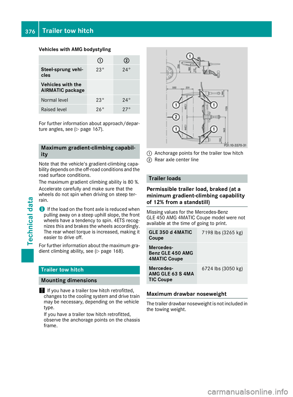
If you have a trailer tow hitch retrofitted,
observe the anchorage points on the chassis
frame.
:Anchorage points for the trailer tow hitch
;Rear axle center line
Trailer loads
Permissible trailer load, braked (at a
minimum gradient-climbing capability
of 12% from a standstill)
Missing values for the Mercedes-Benz
GLE 450 AMG 4MATIC Coupe model were not
available at the time of going to print.
GLE 350 d 4MATIC
Coupe7198 lbs (3265 kg)
Mercedes-
Benz GLE 450 AMG
4MATIC Coupe
Mercedes-
AMG GLE 63 S 4MA
TIC Coupe6724 lbs (3050 kg)
Maximum drawbar noseweight
The trailer drawbar noseweight is not included in
the towing weight.
376Trailer tow hitch
Technical data
Page 379 of 382
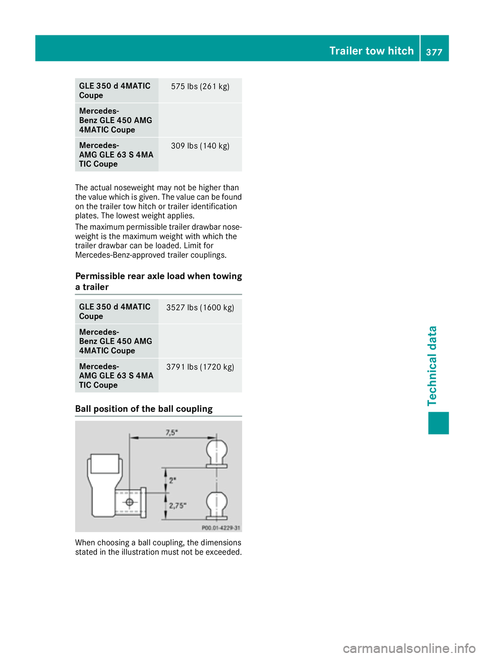
GLE 350 d 4MATIC
Coupe575 lbs (261 kg)
Mercedes-
Benz GLE 450 AMG
4MATIC Coupe
Mercedes-
AMG GLE 63 S 4MA
TIC Coupe309 lbs (140 kg)
The actual noseweight may not be higher than
the value which is given. The value can be found
on the trailer tow hitch or trailer identification
plates. The lowest weight applies.
The maximum permissible trailer drawbar nose-
weight is the maximum weight with which the
trailer drawbar can be loaded. Limit for
Mercedes-Benz-approved trailer couplings.
Permissible rear axle load when towing
a trailer
GLE 350 d 4MATIC
Coupe3527 lbs (1600 kg)
Mercedes-
Benz GLE 450 AMG
4MATIC Coupe
Mercedes-
AMG GLE 63 S 4MA
TIC Coupe3791 lbs (1720 kg)
Ball position of the ball coupling
When choosing a ball coupling, the dimensions
stated in the illustration must not be exceeded.
Trailer tow hitch377
Technical data
Z