2016 MERCEDES-BENZ GLE-CLASS COUPE phone
[x] Cancel search: phonePage 318 of 382
XVehicles with the AIRMATIC package:
make sure that the normal vehicle level is
selected (
Ypage 183).
XSwitch off the engine.
XVehicles without KEYLESS-GO:remove the
SmartKey from the ignition lock.
XVehicles with KEYLESS-GO: open the driv-
er's door.
The on-board electronics now have status 0.
This is the same as the SmartKey having been
removed.
XVehicles with KEYLESS-GO: remove the
Start/Stop button from the ignition lock
(
Ypage 134).
XMake sure that the engine cannot be started
via your smartphone (Ypage 136).
XMake sure that the passengers are not endan-
gered as they do so. Make sure that no one is
near the danger area while a wheel is being
changed. Anyone who is not directly assisting
in the wheel change should, for example,
stand behind the barrier.
XGet out of the vehicle. Pay attention to traffic
conditions when doing so.
XClose the driver's door.
iOnly operate the tire inflation compressor
using a 12 V socket, even if the ignition is
turned off (
Ypage 289).
An emergency cut-out ensures that the on-
board voltage does not drop too low. If the on-
board voltage is too low, the power to the
sockets is automatically cut. This ensures
that there is sufficient power to start the
engine.
MOExtended tires (tires with run-flat
properties)
General notes
With MOExtended tires (tires with run flat char-
acteristics), you can continue to drive your vehi-
cle even if there is a total loss of pressure in one
or more tires. The affected tire must not show
any clearly visible damage.
You can recognize MOExtended tires by the
MOExtended marking which appears on the
sidewall of the tire. You will find this marking
next to the tire size designation, the load-bear-
ing capacity and the speed index (
Ypage 346). MOExtended tires may only be used in conjunc-
tion with an active tire pressure loss warning
system or with an active tire pressure monitor.
If a pressure loss warning message appears
in the multifunction display:
Robserve the instructions in the display mes-
sages (Ypage 259).
Rcheck the tire for damage.
Rif driving on, observe the following notes.
The driving distance possible in run-flat mode is
approximately 50 miles (80 km) when the vehi-
cle is partially laden and approximately 18 miles
(30 km) when the vehicle is fully laden.
In addition to the vehicle load, the driving dis-
tance possible depends upon:
Rvehicle speed
Rroad condition
Routside temperature
The driving distance possible in run-flat mode
may be reduced by extreme driving conditions
or maneuvers, or it can be increased through a
moderate style of driving.
The driving dista
nce possible in run-flat mode is
counted from the moment the tire pressure loss
warning appears in the multifunction display.
You must not exceed a maximum speed of
50 mph (80 km/h).
When replacing one or all tires, please observe
the following specifications for your vehicle's
tires:
Rsize
Rtype and
Rthe "MOExtended" mark
Vehicles equipped with MOExtended tires are
not equipped with a TIREFIT kit at the factory. It
is therefore recommended that you additionally
equip your vehicle with a TIREFIT kit if you mount tires that do not feature run-flat properties, e.g.
winter tires. A TIREFIT kit may be obtained from
a qualified specialist workshop.
Important safety notes
GWARNING
When driving in emergency mode, the driving
characteristics deteriorate, e.g. when corner-
ing, accelerating quickly and when braking.
There is a risk of an accident.
316Flat tire
Breakdown assitance
Page 330 of 382
You can find information on "Jump-starting"
under (Ypage 323).
Fuses
Important safety notes
GWARNING
If you manipulate or bridge a faulty fuse or if
you replace it with a fuse with a higher amper- age, the electric cables could be overloaded.
This could result in a fire. There is a risk of an
accident and injury.
Always replace faulty fuses with the specified
new fuses having the correct amperage.
!For the fuse boxes in the engine compart-
ment and under the rear bench seat, only use
fuses with the suffix "S". Otherwise, compo-
nents or systems could be damaged.
The fuses in your vehicle serve to close down
faulty circuits. If a fuse blows, all the compo-
nents on the circuit and their functions stop
operating.
Blown fuses must be replaced with fuses of the
same rating, which you can recognize by the
color and value. The fuse ratings are listed in the fuse allocation chart.
The fuse allocation chart is located in the fuse
box under the rear bench seat (
Ypage 329).
If a newly inserted fuse also blows, have the
cause traced and rectified at a qualified special-
ist workshop, e.g. an authorized Mercedes-Benz Center.
Before changing a fuse
Observe the important safety notes
(Ypage 328)
XSecure the vehicle against rolling away
(Ypage 156).
XSwitch off the engine.
XSwitch off all electrical consumers.
XRemove the SmartKey from the ignition lock.
or, in vehicles with KEYLESS-GO start-function
or KEYLESS‑ GO
XOpen the driver's door.
The on-board electronics now have status 0.
This is the same as the SmartKey having been
removed.
The driver’s door can be closed again.
XMake sure that the engine cannot be started
via your smartphone (Ypage 136).
All indicator lamps in the instrument cluster
must be off.
The fuses are located in various fuse boxes:
RFuse box on the front-passenger side of the
dashboard
RFuse box in the engine compartment on the
right-hand side of the vehicle, when viewed in
the direction of travel
RFuse box under the rear bench seat
Dashboard fuse box
Pay attention to the important safety notes
(Ypage 328).
!Do not use a pointed object such as a screw-
driver to open the cover in the dashboard. You
could damage the dashboard or the cover.
!Make sure that no moisture can enter the
fuse box when the cover is open.
!When closing the cover, make sure that it is
lying correctly on the fuse box. Moisture seep-
ing in or dirt could otherwise impair the oper-
ation of the fuses.
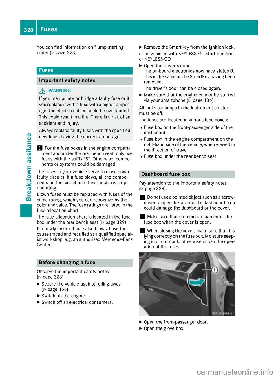
XOpen the front-passenger door.
XOpen the glove box.
328Fuses
Breakdown assitance
Page 341 of 382

halt by braking carefully. Avoid abrupt steering
movements.
The tire pressure monitor has a yellow warning
lamp in the instrument cluster for indicating
pressure loss or a malfunction. Whether the
warning lamp flashes or lights up indicates
whether a tire pressure is too low or the tire
pressure monitor is malfunctioning:
Rif the warning lamp is lit continuously, the tire
pressure on one or more tires is significantly
too low. The tire pressure monitor is not mal-functioning.
Rif the warning lamp flashes for around a
minute and then remains lit constantly, the
tire pressure monitor is malfunctioning.
In addition to the warning lamp, a message
appears in the multifunction display. Observe
the information on display messages
(
Ypage 259).
It may take up to ten minutes for a malfunction of the tire pressure monitor to be indicated. A
malfunction will be indicated by the tire pres-
sure warning lamp flashing for approximately
one minute and then remaining lit. When the
malfunction has been rectified, the tire pressure
warning lamp goes out after a few minutes of
driving.
The tire pressure values indicated by the on-
board computer may differ from those meas-
ured at a gas station with a pressure gauge. The
tire pressures shown by the on-board computer
refer to those measured at sea level. At high
altitudes, the tire pressure values indicated by a
pressure gauge are higher than those shown by the on-board computer. In this case, do not
reduce the tire pressures.
The operation of the tire pressure monitor can
be affected by interference from radio transmit-
ting equipment (e.g. radio headphones, two-way
radios) that may be being operated in or near the vehicle.
Checking the tire pressure electroni-
cally
XMake sure that the SmartKey is in position 2
in the ignition lock (Ypage 134).
XPress the =or; button on the steering
wheel to select the Serv.menu.
XPress the9or: button to select
Tire Pressure.
XPress the abutton.
The current tire pressure of each tire is shown
in the multifunction display.
If the vehicle has been parked for longer than
20 minutes, the Tire pressure will be
displayed after driving a few minutesmessage appears.
After a teach-in process, the tire pressure mon-
itor automatically detects new wheels or new
sensors. As long as a clear allocation of the tire
pressure value to the individual wheels is not
possible, theTire
PressureMonitorActivedisplay message is shown instead of the tire
pressure display. The tire pressures are already
being monitored.
iIf an emergency spare wheel is mounted,
the system may continue to show the tire
pressure of the wheel that has been removed
for a few minutes. If this occurs, note that the
value displayed for the position where the
spare wheel is mounted is not the same as the
current tire pressure of the emergency spare
wheel.
Tire pressure monitor warning mes-
sages
If the tire pressure monitor detects a pressure
loss in one or more tires, a warning message is
shown in the multifunction display. The yellow
tire pressure warning lamp then lights up.
RIf the Please Correct Tire Pressuremessage appears in the multifunction display,
the tire pressure in at least one tire is too low.
The tire pressure must be corrected when the
opportunity arises.
RIf the Check Tiresmessage appears in the
multifunction display, the tire pressure in at
least one tire has dropped significantly. The
tires must be checked.
RIf the WarningTireMalfunctionmessage
appears in the multifunction display, the tire
pressure in at least one tire has dropped sud-
denly. The tires must be checked.
If the wheel positions on the vehicle are rotated, the tire pressures may be displayed for the
wrong positions for a short time. This is rectified
after a few minutes of driving, and the tire pres-
sures are displayed for the correct positions.
Tire pressure339
Wheels and tires
Z
Page 354 of 382
be required earlier. Do not change the direction
of wheel rotation.
Clean the contact surfaces of the wheel and the
brake disc thoroughly every time a wheel is rota-ted. Check the tire pressure and, if necessary,
restart the tire pressure loss warning system or
the tire pressure monitor.
Direction of rotation
Tires with a specified direction of rotation have
additional benefits, e.g. if there is a risk of hydro-
planing. These advantages can only be gained if
the tires are installed corresponding to the
direction of rotation.
An arrow on the sidewall of the tire indicates its
correct direction of rotation.
Storing wheels
Store wheels that are not being used in a cool,
dry and preferably dark place. Protect the tires
from oil, grease, gasoline and diesel.
Mounting a wheel
Preparing the vehicle
XVehicle with emergency spare wheel:
when mounting the emergency spare wheel in
the event of a flat tire, follow the additional
notes on vehicle preparation under "Flat tire"
(
Ypage 315).
XStop the vehicle on solid, non-slippery and
level ground.
XApply the electric parking brake manually.
XUnload heavy luggage.
XBring the front wheels into the straight-ahead position.
XShift the transmission to position P.
XVehicles with the AIRMATIC package:
make sure that the normal vehicle level is
selected (
Ypage 183).
XSwitch off the engine.
XVehicles without KEYLESS-GO:remove the
SmartKey from the ignition lock.
XVehicles with KEYLESS-GO: open the driv-
er's door.
The on-board electronics now have status 0.
This is the same as the SmartKey having been
removed.
XVehicles with KEYLESS-GO: remove the
Start/Stop button from the ignition lock
(
Ypage 134).
XMake sure that the engine cannot be started
via your smartphone (Ypage 136).
XIf included in the vehicle equipment, remove
the tire-change tool kit from the vehicle.
XSafeguard the vehicle against rolling away.
iApart from certain country-specific varia-
tions, vehicles are not equipped with a tire-
change tool kit. For information on which
tools are required to perform a wheel change
on your vehicle, consult an authorized
Mercedes-Benz Center.
Necessary tire-changing tools can include, for example:
RJack
RWheel chock
RLug wrench
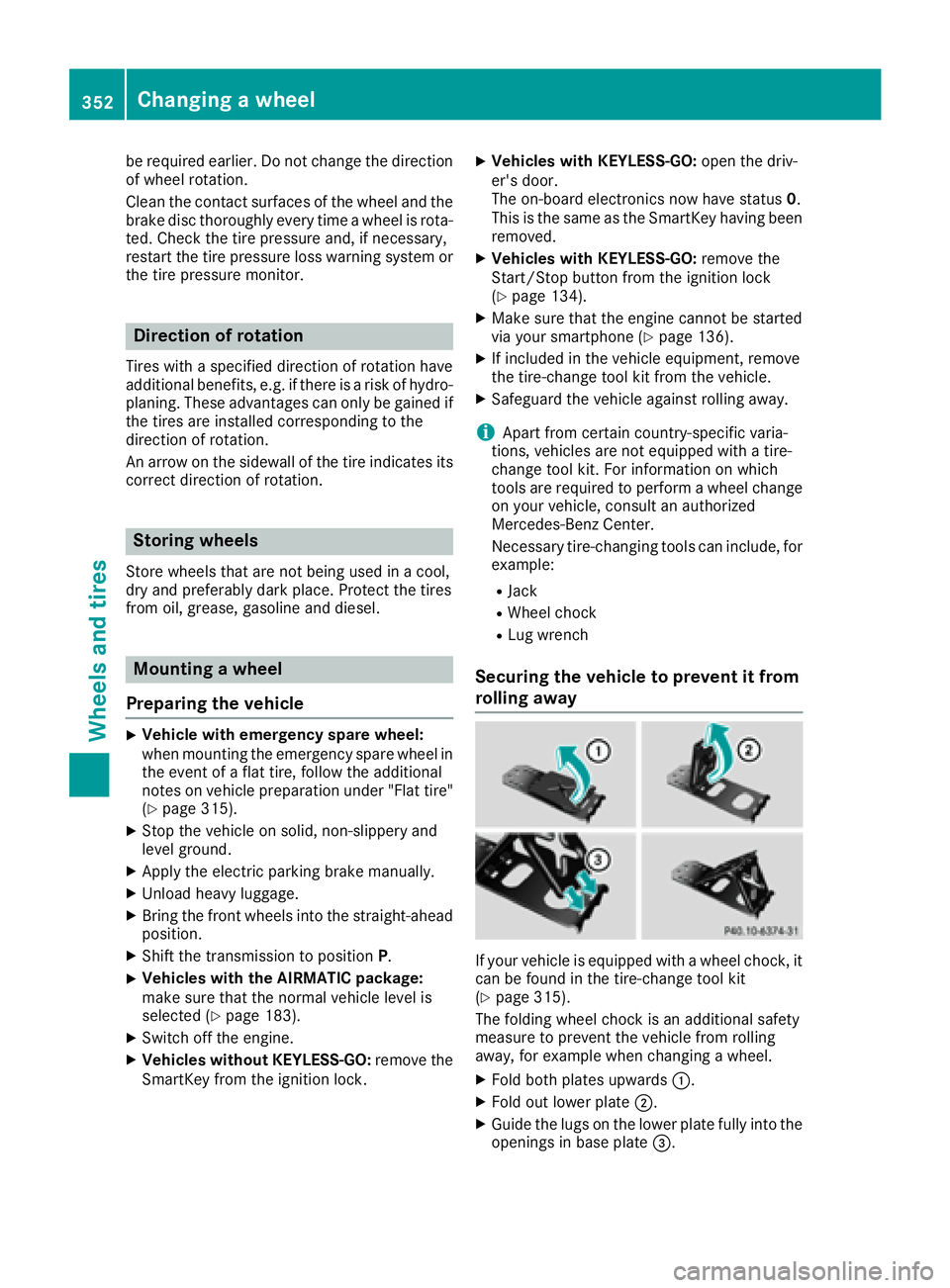
Securing the vehicle to prevent it from
rolling away
If your vehicle is equipped with a wheel chock, itcan be found in the tire-change tool kit
(
Ypage 315).
The folding wheel chock is an additional safety
measure to prevent the vehicle from rolling
away, for example when changing a wheel.
XFold both plates upwards :.
XFold out lower plate;.
XGuide the lugs on the lower plate fully into the
openings in base plate =.
352Changing a wheel
Wheels and tires
Page 367 of 382
Useful information
i
This Operator's Manual describes all models
and all standard and optional equipment of
your vehicle available at the time of publica-
tion of the Operator's Manual. Country-spe-
cific differences are possible. Please note
that your vehicle may not be equipped with all
features described. This also applies to
safety-related systems and functions.
iRead the information on qualified specialist
workshops (Ypage 26).
Information regarding technical data
i
The data stated here specifically refers to a
vehicle with standard equipment. Consult an
authorized Mercedes-Benz Center for the
data for all vehicle variants and trim levels.
Vehicle electronics
Retrofitting two-way radios and
mobile phones (RF transmitters)
GWARNING
The electromagnetic radiation from modified
or incorrectly retrofitted RF-transmitters can
interfere with the vehicle electronics. This can compromise the operational safety of the
vehicle. There is a risk of an accident.
You should have all work to electrical and
electronic equipment carried out at a qualified
specialist workshop.
GWARNING
The electromagnetic radiation from incor-
rectly operated RF transmitters can interfere
with the vehicle electronics, for example:
Rif the RF transmitter is not connected with
an exterior antenna
Rthe exterior antenna has been installed
incorrectly or is not a low-reflection type
This can compromise the operational safety
of the vehicle. There is a risk of an accident.
Have the low-reflection exterior antenna
mounted at a qualified specialist workshop.
When operating RF transmitters in the vehi-
cle, always connect them with the low-reflec- tion exterior antenna.
!The operating permit may be invalidated if
the instructions for installation and use of RF
transmitters are not observed.
In particular, the following conditions must be complied with:
Ronly approved wavebands may be used.
Rcompliance with the maximum permissibleoutput in these wavebands is required.
Ronly approved antenna positions may be
used.
Excessive levels of electromagnetic radiation
may cause damage to your health and the health
of others. Using an exterior antenna takes into
account current scientific discussions relating
to the possible health hazards that may result
from electromagnetic fields.
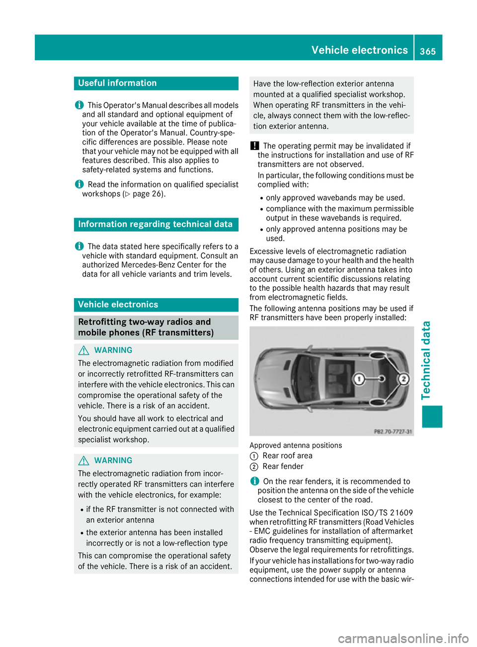
The following antenna positions may be used if
RF transmitters have been properly installed:
Approved antenna positions
:
Rear roof area
;Rear fender
iOn the rear fenders, it is recommended to
position the antenna on the side of the vehicle
closest to the center of the road.
Use the Technical Specification ISO/TS 21609
when retrofitting RF transmitters (Road Vehicles
- EMC guidelines for installation of aftermarket
radio frequency transmitting equipment).
Observe the legal requirements for retrofittings.
If your vehicle has installations for two-way radio
equipment, use the power supply or antenna
connections intended for use with the basic wir-
Vehicle electronics365
Technical data
Z
Page 368 of 382

ing. Be sure to observe the manufacturer's addi-
tional instructions when installing.
Deviations with respect to wavebands, maxi-
mum transmission outputs or antenna positions
must be approved by Mercedes-Benz.
The maximum transmission output (PEAK) at the
base of the antenna must not exceed the fol-
lowing values:
WavebandMaximum
transmission output
Short wave
3 - 54 MHz100 W
4 m waveband
74 - 88 MHz30 W
2 m waveband
144 - 174 MHz50 W
Trunked radio/Tetra
380 - 460 MHz10 W
70 cm waveband
400 - 460 MHz35 W
Mobile communications
(2G/3G/4G)10 W
The following can be used in the vehicle without
restrictions:
RRF transmitters with a maximum transmis-
sion output of up to 100 mW
RRF transmitters with transmitter frequencies
in the 380 - 410 MHz waveband and a maxi-
mum transmission output of up to 2 W
(trunked radio/Tetra)
RMobile telephones (2G/3G/4G)
There is no restriction for antenna positions on
the outside of the vehicle for the following wave-
bands:
RTrunked radio/Tetra
R70 cm waveband
R2G/3G/4G
Identification plates
Vehicle identification plate with vehi-
cle identification number (VIN)
XOpen the driver's door.
You will see vehicle identification plate :.
Example: vehicle identification plate (USA only)
;
Paint code
=VIN
Example: vehicle identification plate (Canada only)
;
Paint code
=VIN
iThe data shown on the vehicle identification
plate is used only as an example. This data is
different for every vehicle and can deviate
366Identification plates
Technical data