2016 MERCEDES-BENZ GLE-CLASS COUPE turn signal
[x] Cancel search: turn signalPage 217 of 382
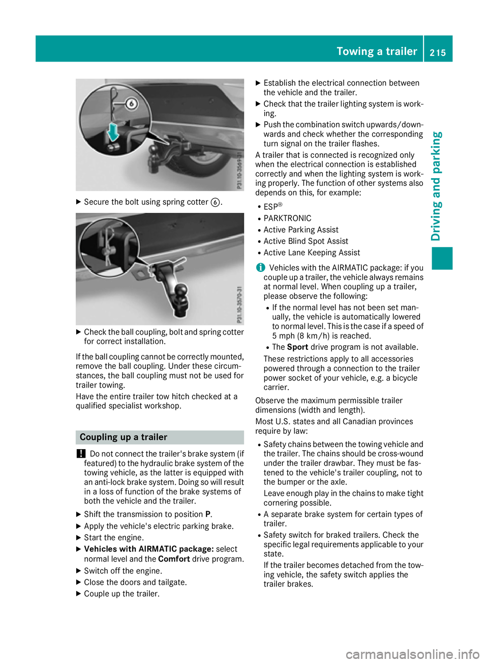
XSecure the bolt using spring cotterB.
XCheck the ball coupling, bolt and spring cotter
for correct installation.
If the ball coupling cannot be correctly mounted,
remove the ball coupling. Under these circum-
stances, the ball coupling must not be used for
trailer towing.
Have the entire trailer tow hitch checked at a
qualified specialist workshop.
Coupling up a trailer
!
Do not connect the trailer's brake system (if
featured) to the hydraulic brake system of the
towing vehicle, as the latter is equipped with
an anti-lock brake system. Doing so will result
in a loss of function of the brake systems of
both the vehicle and the trailer.
XShift the transmission to position P.
XApply the vehicle's electric parking brake.
XStart the engine.
XVehicles with AIRMATIC package: select
normal level and the Comfortdrive program.
XSwitch off the engine.
XClose the doors and tailgate.
XCouple up the trailer.
XEstablish the electrical connection between
the vehicle and the trailer.
XCheck that the trailer lighting system is work-
ing.
XPush the combination switch upwards/down-
wards and check whether the corresponding
turn signal on the trailer flashes.
A trailer that is connected is recognized only
when the electrical connection is established
correctly and when the lighting system is work-
ing properly. The function of other systems also
depends on this, for example:
RESP®
RPARKTRONIC
RActive Parking Assist
RActive Blind Spot Assist
RActive Lane Keeping Assist
iVehicles with the AIRMATIC package: if you
couple up a trailer, the vehicle always remains
at normal level. When coupling up a trailer,
please observe the following:
RIf the normal level has not been set man-
ually, the vehicle is automatically lowered
to normal level. This is the case if a speed of
5 mph (8 km/h) is reached.
RThe Sport drive program is not available.
These restrictions apply to all accessories
powered through a connection to the trailer
power socket of your vehicle, e.g. a bicycle
carrier.
Observe the maximum permissible trailer
dimensions (width and length).
Most U.S. states and all Canadian provinces
require by law:
RSafety chains between the towing vehicle and
the trailer. The chains should be cross-wound
under the trailer drawbar. They must be fas-
tened to the vehicle's trailer coupling, not to
the bumper or the axle.
Leave enough play in the chains to make tight
cornering possible.
RA separate brake system for certain types of
trailer.
RSafety switch for braked trailers. Check the
specific legal requirements applicable to your
state.
If the trailer becomes detached from the tow-
ing vehicle, the safety switch applies the
trailer brakes.
Towing a trailer215
Driving and parking
Z
Page 248 of 382
Display messagesPossible causes/consequences andMSolutions
XVisitaqualified specialist workshop immediately.
Fo rfurther information about th eOccupant Classification System, see
(
Ypage 46).
Lights
i
Vehicles wit hLE Dbulbs in th eligh tclusters :
The display message for th ecorrespondin glamp only appear swhen all of th eLEDs in th elamp
hav efailed.
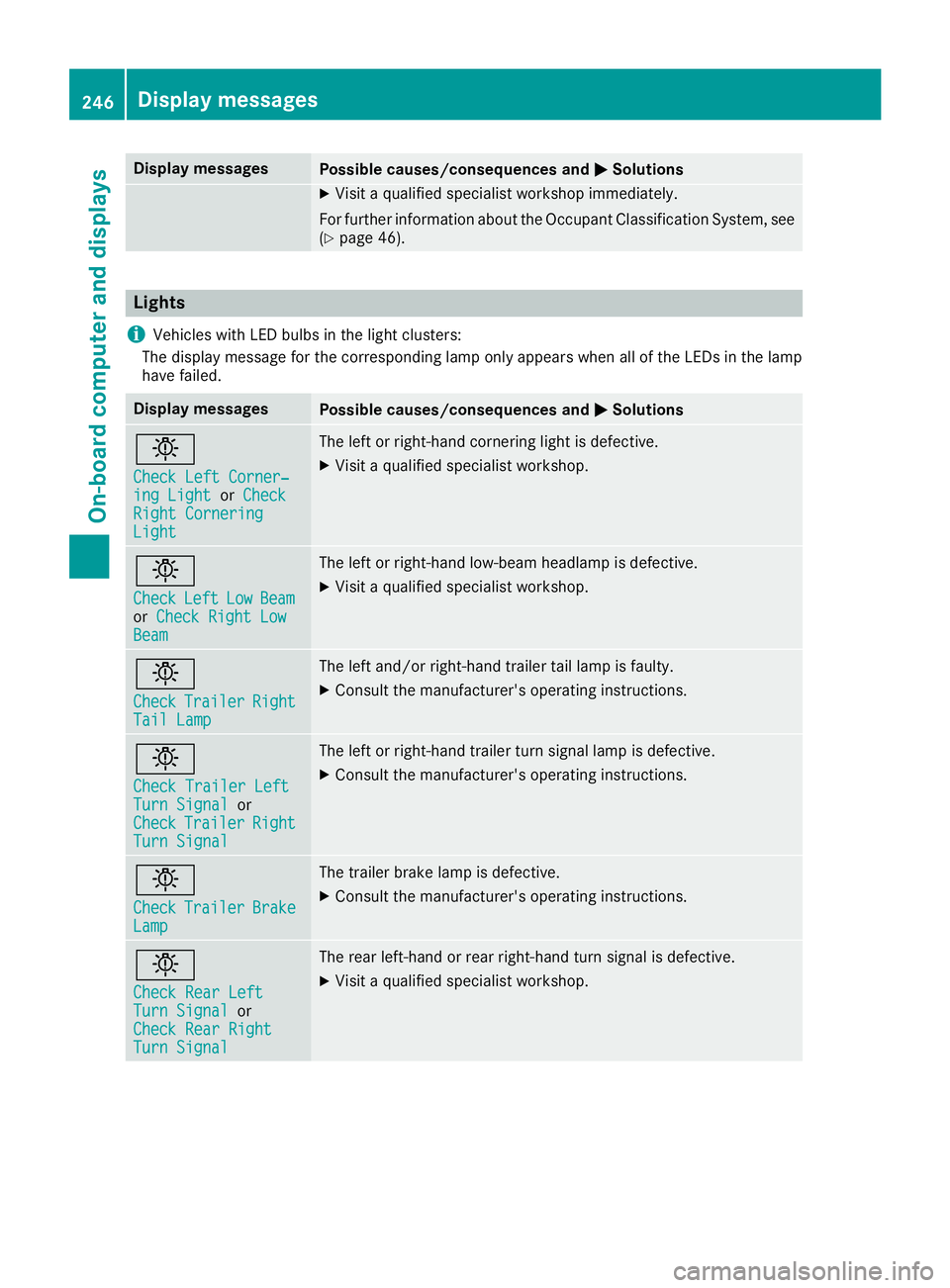
Display messagesPossible causes/consequences and MSolutions
b
Check LeftCorner ‐ing LightorCheckRight CorneringLight
The lef tor right-hand cornering ligh tis defective.
XVisit aqualified specialist workshop .
b
CheckLeftLowBeamorCheck Right LowBea m
The lef tor right-hand low-beam headlamp is defective.
XVisit aqualified specialist workshop .
b
CheckTrailerRightTailLam p
The lef tand/o rright-hand trailer tai llamp is faulty.
XConsult th emanufacturer' soperating instructions.
b
Check Traile rLef tTurnSignalor
CheckTraile rRightTurnSignal
The lef tor right-hand trailer tur nsignal lamp is defective.
XConsult th emanufacturer' soperating instructions.
b
CheckTraile rBrakeLamp
The trailer brak elamp is defective.
XConsult th emanufacturer' soperating instructions.
b
Check Rea rLef tTurnSignalor
Check Rea rRight
Tur nSignal
The rear left-han dor rear right-hand tur nsignal is defective.
XVisit aqualified specialist workshop .
246Display messages
On-board computer and displays
Page 249 of 382
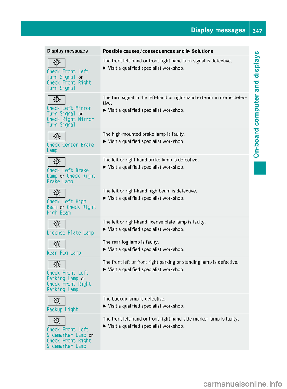
Display messagesPossible causes/consequences andMSolutions
b
Check Front LeftTurnSignalor
Check Front Right
Tur nSignal
The fron tleft-han dor fron tright-hand tur nsignal is defective.
XVisit aqualified specialist workshop .
b
Check LeftMirrorTur nSignalor
Check Right Mirror
Tur nSignal
The tur nsignal in th eleft-han dor right-hand exterio rmirror is defec -
tive.
XVisit aqualified specialist workshop .
b
Check Center BrakeLamp
The high-mounte dbrak elamp is faulty.
XVisit aqualified specialist workshop .
b
Check LeftBrakeLam porCheck RightBrake Lam p
The leftor right-hand brak elamp is defective.
XVisit aqualified specialist workshop .
b
Check LeftHig hBeamorCheck RightHig hBea m
The lef tor right-hand high beam is defective.
XVisit aqualified specialist workshop .
b
LicensePlate Lam p
The leftor right-hand license plat elamp is faulty.
XVisit aqualified specialist workshop .
b
RearFog Lam p
The rear fog lamp is faulty.
XVisitaqualified specialist workshop .
b
Check Front LeftParkingLam por
Check Front Right
Parkin gLam p
The fron tlef tor fron tright parking or standing lamp is defective.
XVisit aqualified specialist workshop .
b
Backup Light
The backup lamp is defective.
XVisitaqualified specialist workshop .
b
Check Front LeftSidemarkerLam por
Check Front Right
Sidemarke rLam p
The fron tleft-han dor fron tright-hand side marke rlamp is faulty.
XVisit aqualified specialist workshop .
Display messages247
On-board computer and displays
Z
Page 301 of 382
Programming
Programming buttons
Pay attention to the "Important safety notes"
(Ypage 298).
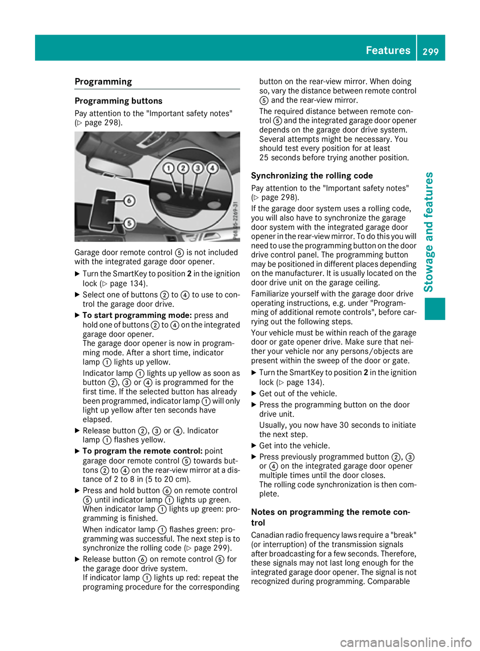
Garage door remote controlAis not included
with the integrated garage door opener.
XTurn the SmartKey to position 2in the ignition
lock (Ypage 134).
XSelect one of buttons ;to? to use to con-
trol the garage door drive.
XTo start programming mode: press and
hold one of buttons ;to? on the integrated
garage door opener.
The garage door opener is now in program-
ming mode. After a short time, indicator
lamp :lights up yellow.
Indicator lamp :lights up yellow as soon as
button ;,=or? is programmed for the
first time. If the selected button has already
been programmed, indicator lamp :will only
light up yellow after ten seconds have
elapsed.
XRelease button ;,=or?. Indicator
lamp :flashes yellow.
XTo program the remote control: point
garage door remote control Atowards but-
tons ;to? on the rear-view mirror at a dis-
tance of 2 to 8 in (5 to 20 cm).
XPress and hold button Bon remote control
A until indicator lamp :lights up green.
When indicator lamp :lights up green: pro-
gramming is finished.
When indicator lamp :flashes green: pro-
gramming was successful. The next step is to synchronize the rolling code (
Ypage 299).
XRelease button Bon remote control Afor
the garage door drive system.
If indicator lamp :lights up red: repeat the
programing procedure for the corresponding button on the rear-view mirror. When doing
so, vary the distance between remote control
A
and the rear-view mirror.
The required distance between remote con-
trol Aand the integrated garage door opener
depends on the garage door drive system.
Several attempts might be necessary. You
should test every position for at least
25 seconds before trying another position.
Synchronizing the rolling code
Pay attention to the "Important safety notes"
(Ypage 298).
If the garage door system uses a rolling code,
you will also have to synchronize the garage
door system with the integrated garage door
opener in the rear-view mirror. To do this you will
need to use the programming button on the door
drive control panel. The programming button
may be positioned in different places depending
on the manufact
urer. It is usually located on the
door drive unit on the garage ceiling.
Familiarize yourself with the garage door drive
operating instructions, e.g. under "Program-
ming of additional remote controls", before car-
rying out the following steps.
Your vehicle must be within reach of the garage
door or gate opener drive. Make sure that nei-
ther your vehicle nor any persons/objects are
present within the sweep of the door or gate.
XTurn the SmartKey to position 2in the ignition
lock (Ypage 134).
XGet out of the vehicle.
XPress the programming button on the door
drive unit.
Usually, you now have 30 seconds to initiate
the next step.
XGet into the vehicle.
XPress previously programmed button ;,=
or ? on the integrated garage door opener
multiple times until the door closes.
The rolling code synchronization is then com- plete.
Notes on programming the remote con-
trol
Canadian radio frequency laws require a "break"
(or interruption) of the transmission signals
after broadcasting for a few seconds. Therefore,
these signals may not last long enough for the
integrated garage door opener. The signal is not
recognized during programming. Comparable
Features299
Stowage and features
Z
Page 302 of 382
with Canadian law, some U.S. garage door open-
ers also feature a "break".
Proceed as follows:
Rif you live in Canada
Rif you have difficulties programming the
garage door opener (regardless of where you
live) when using the programming steps
XPress and hold one of buttons;to? on the
integrated garage door opener.
After a short time, indicator lamp :lights up
yellow.
XRelease the button.
Indicator lamp :flashes yellow.
XPress button Bof garage door remote con-
trol Afor two seconds, then release it for two
seconds.
XPress button Bagain for two seconds.
XRepeat this sequence on button Bof remote
control Auntil indicator lamp :lights up
green.
When indicator lamp :lights up green: pro-
gramming is finished.
When indicator lamp :flashes green: pro-
gramming was successful. The next step is to
synchronize the rolling code.
XRelease button Bof remote control Aof the
garage door drive.
If indicator lamp :lights up red: repeat the
programming process for the corresponding
button on the rear-view mirror. When doing
so, vary the distance between remote control
A and the rear-view mirror.
The required distance between remote con-
trol Aand the integrated garage door opener
depends on the garage door drive system.
Several attempts might be necessary. You
should test every position for at least
25 seconds before trying another position.
Problems when programming
If you are experiencing problems programing
th e integrated garage door opener on the rear-
view mirror, take note of the following instruc-
tions:
RCheck the transmitter frequency used by
garage door drive remote control Aand
whether it is supported. The transmitter fre-
quency can usually be found on the back of
the garage door drive remote control.
The integrated garage door opener is com-
patible with devices that have units which operate in the frequency range of 280 to
433 MHz.
RReplace the batteries in garage door remote
control
A. This increases the likelihood that
garage door remote control Awill transmit a
strong and precise signal to the integrated
garage door opener.
RWhen programming, hold remote control A
at varying distances and angles from the but-
ton which you are programming. Try various
angles at a distance between 2and 12 inches
(5to 30 cm) or at the same angle but at varying
distances.
RIf another remote control is available for the
same garage door drive, repeat the same pro-
gramming steps with this remote control.
Before performing these steps, make sure
that new batteries have been installed in
garage door drive remote control A.
RNote that some remote controls only transmit
for a limited amount of time (the indicator
lamp on the remote control goes out). Press
buttonBon remote control Aagain before
transmission ends.
RAlign the antenna cable of the garage door
open er unit. This can improve signal recep-
tion/transmission.
Opening/closing the garage door
After it has been programmed, the integrated
garage door opener performs the function of the
garage door system remote control. Please also
read the operating instructions for the garage
door system.
XTurn the SmartKey to position 2in the ignition
lock (Ypage 134).
XPress button ;,=or? which you have
programmed to operate the garage door.
Garage door system with a fixed code: indi-
cator lamp :lights up green.
Garage door system with a rolling code: indi-
cator lamp :flashes green.
The transmitter will transmit a signal as long
as the button is pressed. The transmission is
halted after a maximum of ten seconds and
indicator lamp :lights up yellow.
XPress button ;,=or? again if necessary.
300Features
Stowage and features
Page 313 of 382

Cleaning the exterior lighting
!Only use cleaning agents or cleaning cloths
which are suitable for plastic light lenses.
Unsuitable cleaning agents or cleaning cloths
could scratch or damage the plastic light len- ses.
XClean the plastic lenses of the exterior light-
ing using a wet sponge and a mild cleaning
agent, e. g. Mercedes-Benz car shampoo or
cleaning cloths.
Cleaning the mirror turn signals
!Only use cleaning agents or cleaning cloths
that are suitable for plastic lenses. Unsuitable
cleaning agents or cleaning cloths could
scratch or damage the plastic lenses of the
mirror turn signals.
XClean the plastic lenses of the mirror turn sig-
nals in the exterior mirror housing using a wet
sponge and mild cleaning agent, e.g.
Mercedes-Benz car shampoo or cleaning
cloths.
Cleaning the side running board
!Do not clean the aluminum inserts of the
side running board with alkaline or acidic
cleaners, such as wheel cleaner. Do not use
acidic wheel cleaners to remove brake dust.
The aluminum inserts could otherwise be
damaged.
Cleaning the sensors
!If you clean the sensors with a power
washer, make sure that you keep a distance
of at least 11.8 in (30 cm) between the vehicle
and the power washer nozzle. Information
about the correct distance is available from
the equipment manufacturer.
XClean sensors :of the driving systems with
water, car shampoo and a soft cloth.
Cleaning the rear view camera
!Do not clean the camera lens and the area
around the rear view camera with a power
washer.
XMake sure that the vehicle is stationary and
that the SmartKey is in position 2in the igni-
tion lock.
XOpen the camera cover for cleaning via the
multimedia system (see the separate operat-
ing instructions).
XTo clean the rear view camera: use clear
water and a soft cloth to clean camera
lens :.
Care311
Maintenance and care
Z
Page 329 of 382
In order to ensure that the automatic transmis-
sion stays in positionNwhen towing the vehicle,
you must observe the following points:
XMake sure that the vehicle is stationary.
XTurn the SmartKey to position 2in the ignition
lock.
XDepress and hold the brake pedal.
XShift the automatic transmission to position
N.
XLeave the SmartKey in position 2in the igni-
tion lock.
XRelease the brake pedal.
XRelease the electric parking brake.
XSwitch on the hazard warning lamps
(Ypage 110).
In order to signal a change of direction when
towing the vehicle with the hazard warning
lamps switched on, use the combination switch
as usual. In this case, only the indicator lamps
for the direction of travel flash. After resetting
the combination switch, the hazard warning
lamp starts flashing again.
Transporting the vehicle
4MATIC vehicles/vehicles with auto-
matic transmission
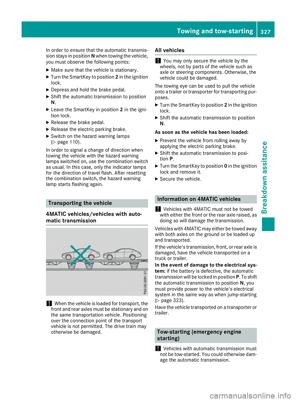
!When the vehicle is loaded for transport, the
front and rear axles must be stationary and on the same transportation vehicle. Positioning
over the connection point of the transport
vehicle is not permitted. The drive train may
otherwise be damaged.
All vehicles
!You may only secure the vehicle by the
wheels, not by parts of the vehicle such as
axle or steering components. Otherwise, the
vehicle could be damaged.
The towing eye can be used to pull the vehicle
onto a trailer or transporter for transporting pur-
poses.
XTurn the SmartKey to position 2in the ignition
lock.
XShift the automatic transmission to position
N.
As soon as the vehicle has been loaded:
XPrevent the vehicle from rolling away by
applying the electric parking brake.
XShift the automatic transmission to posi-
tion P.
XTurn the SmartKey to position 0in the ignition
lock and remove it.
XSecure the vehicle.
Information on 4MATIC vehicles
!
Vehicles with 4MATIC must not be towed
with either the front or the rear axle raised, as
doing so will damage the transmission.
Vehicles with 4MATIC may either be towed away with both axles on the ground or be loaded up
and transported.
If the vehicle's transmission, front, or rear axle is
damaged, have the vehicle transported on a
truck or trailer.
In the event of damage to the electrical sys-
tem: if the battery is defective, the automatic
transmission will be locked in position P. To shift
the automatic transmission to position N, you
must provide power to the vehicle's electrical
system in the same way as when jump-starting
(
Ypage 323).
Have the vehicle transported on a transporter or
trailer.
Tow-starting (emergency engine
starting)
!
Vehicles with automatic transmission must
not be tow-started. You could otherwise dam-
age the automatic transmission.
Towing and tow-starting327
Breakdown assitance
Z