2016 MERCEDES-BENZ GLE-CLASS COUPE tire type
[x] Cancel search: tire typePage 215 of 382
RThe bumpers of your vehicle are not suitable
for installing detachable trailer couplings.
RDo not install hired trailer couplings or other
detachable trailer couplings on the bumpers
of your vehicle.
RIf you no longer need the ball coupling,
remove it from the ball coupling recess. This
will reduce the risk of damage to the ball cou-
pling.
When towing a trailer, set the tire pressure on
the rear axle of the towing vehicle for the max-
imum load. You will find the values in the tire
pressure table in the fuel filler flap of the vehicle
(
Ypage 349).
Please note that when towing a trailer, the fol-
lowing driving systems have limited availability
or are not available at all:
RPARKTRONIC (Ypage 186)
RBlind Spot Assist (Ypage 203)
RActive Lane Keeping Assist (Ypage 209)
On vehicles without level control, the height of
the ball coupling will alter according to the load
placed on the vehicle. If necessary, use a trailer
with a height-adjustable drawbar.
You will find installing dimensions and loads
under "Technical data" (
Ypage 376).
Driving tips
Observe the information on ESP®trailer stabili-
zation (Ypage 67) and on pulling away with a
trailer (Ypage 138).
The maximum permissible speed for vehicle/
trailer combinations depends on the type of
trailer. Before beginning the journey, check the
trailer's documents to see what the maximum
permissible speed is. Observe the legally pre-
scribed maximum speed in the relevant country.
For certain Mercedes-Benz vehicles, the maxi-
mum permissible rear axle load is increased
when towing a trailer. See "Technical data" to
find out whether this applies to your vehicle
(
Ypage 376). If you utilize any of the added
maximum rear axle load when towing a trailer,
the vehicle/trailer combination may not exceed
a maximum speed of 60 mph (100 km/h) for
reasons concerning the operating permit. This
also applies in countries in which the permissi-
ble maximum speed for vehicle/trailer combi-
nations is above 60 mph (100 km/h). When towing a trailer, your vehicle's handling
characteristics will be different in comparison
with when driving without a trailer.
Use the left-hand steering wheel paddle shifter
to shift into a lower gear in good time on long
and steep downhill gradients.
This also applies if you have activated cruise
control or DISTRONIC PLUS.
This will use the braking effect of the engine, so
that less braking will be required to maintain the
speed. This relieves the load on the brake sys-
tem and prevents the brakes from overheating
and wearing too quickly. If you need additional
braking, depress the brake pedal repeatedly
rather than continuously.
Driving tips
If the trailer swings from side to side:
XDo not accelerate.
XDo not counter-steer.
XBrake if necessary.
RMaintain a greater distance from the vehicle
in front than when driving without a trailer.
RAvoid braking abruptly. If possible, brake gen-tly at first to allow the trailer to run on. Then,
increase the braking force rapidly.
RThe values given for gradient-climbing capa-
bilities from a standstill refer to sea level.
When driving in mountainous areas, note that
the power output of the engine and, conse-
quently, the vehicle's gradient-climbing capa-
bility, decreases with increasing altitude.
Installing the ball coupling
GWARNING
If the ball coupling is not correctly installed
and secured, it can come loose during the
journey and endanger other road users. There is a risk of an accident and injury.
Always install and secure the ball coupling as
described. Before every journey, ensure that
the ball coupling is secured with the bolt and
the corresponding spring cotter.
GWARNING
If the ball coupling is not installed correctly or not secured with the bolt provided and the
Towing a trailer213
Driving and parking
Z
Page 217 of 382
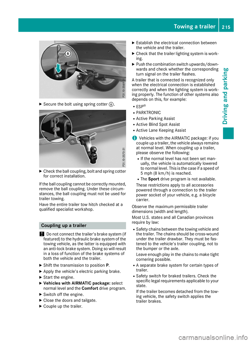
XSecure the bolt using spring cotterB.
XCheck the ball coupling, bolt and spring cotter
for correct installation.
If the ball coupling cannot be correctly mounted,
remove the ball coupling. Under these circum-
stances, the ball coupling must not be used for
trailer towing.
Have the entire trailer tow hitch checked at a
qualified specialist workshop.
Coupling up a trailer
!
Do not connect the trailer's brake system (if
featured) to the hydraulic brake system of the
towing vehicle, as the latter is equipped with
an anti-lock brake system. Doing so will result
in a loss of function of the brake systems of
both the vehicle and the trailer.
XShift the transmission to position P.
XApply the vehicle's electric parking brake.
XStart the engine.
XVehicles with AIRMATIC package: select
normal level and the Comfortdrive program.
XSwitch off the engine.
XClose the doors and tailgate.
XCouple up the trailer.
XEstablish the electrical connection between
the vehicle and the trailer.
XCheck that the trailer lighting system is work-
ing.
XPush the combination switch upwards/down-
wards and check whether the corresponding
turn signal on the trailer flashes.
A trailer that is connected is recognized only
when the electrical connection is established
correctly and when the lighting system is work-
ing properly. The function of other systems also
depends on this, for example:
RESP®
RPARKTRONIC
RActive Parking Assist
RActive Blind Spot Assist
RActive Lane Keeping Assist
iVehicles with the AIRMATIC package: if you
couple up a trailer, the vehicle always remains
at normal level. When coupling up a trailer,
please observe the following:
RIf the normal level has not been set man-
ually, the vehicle is automatically lowered
to normal level. This is the case if a speed of
5 mph (8 km/h) is reached.
RThe Sport drive program is not available.
These restrictions apply to all accessories
powered through a connection to the trailer
power socket of your vehicle, e.g. a bicycle
carrier.
Observe the maximum permissible trailer
dimensions (width and length).
Most U.S. states and all Canadian provinces
require by law:
RSafety chains between the towing vehicle and
the trailer. The chains should be cross-wound
under the trailer drawbar. They must be fas-
tened to the vehicle's trailer coupling, not to
the bumper or the axle.
Leave enough play in the chains to make tight
cornering possible.
RA separate brake system for certain types of
trailer.
RSafety switch for braked trailers. Check the
specific legal requirements applicable to your
state.
If the trailer becomes detached from the tow-
ing vehicle, the safety switch applies the
trailer brakes.
Towing a trailer215
Driving and parking
Z
Page 279 of 382

Tires
Warning/
indicator
lampNSignal type
Possible causes/consequences and M
Solutions
hNThe yellow tire pressure monitor warning lamp (pressure loss/malfunction) is lit.
The tire pressure monitor has detected a loss of pressure in at least one of the tires.
GWARNING
Tire pressures that are too low pose the following hazards:
Rthey may burst, especially as the load and vehicle speed increase.
Rthey may wear excessively and/or unevenly, which may greatly impair tire trac-
tion.
Rthe driving characteristics, as well as steering and braking, may be greatly
impaired.
There is a risk of an accident.
XStop the vehicle without making any sudden steering or braking maneuvers. Pay
attention to the traffic conditions as you do so.
XSecure the vehicle against rolling away (Ypage 156).
XObserve the additional display messages in the multifunction display.
XCheck the tires and, if necessary, follow the instructions for a flat tire
(Ypage 315).
XCheck the tire pressure (Ypage 337).
XIf necessary, correct the tire pressure.
hN The yellow tire pressure monitor warning lamp (pressure loss/malfunction)
flashes for approximately one minute and then remains lit.
The tire pressure monitor is faulty.
GWARNING
The system is possibly unable to recognize or register low tire pressure.
There is a risk of an accident.
XObserve the additional display messages in the multifunction display.
XVisit a qualified specialist workshop immediately.
Warning and indicator lamps in the instrument cluster277
On-board computer and displays
Z
Page 316 of 382
Genuine leather seat covers
!To retain the natural appearance of the
leather, observe the following cleaning
instructions:
RClean genuine leather covers carefully with
a damp cloth and then wipe the covers
down with a dry cloth.
RMake sure that the leather does not
become soaked. It may otherwise become
rough and cracked.
ROnly use leather care agents that have
been tested and approved by Mercedes-
Benz. You can obtain these from a qualified
specialist workshop.
Leather is a natural product.
It exhibits natural surface characteristics, for
example:
Rdifferences in the texture
Rmarks caused by growth and injury
Rslight nuances of color
These are characteristics of leather and not
material defects.
Seat covers of other materials
!Observe the following when cleaning:
Rclean artificial leather covers with a cloth
moistened with a solution containing 1%
detergent (e.g. dish washing liquid).
Rclean cloth covers with a microfiber cloth
moistened with a solution containing 1%
detergent (e.g. dish washing liquid). Rub
carefully and always wipe entire seat sec-
tions to avoid leaving visible lines. Leave
the seat to dry afterwards. Cleaning results
depend on the type of dirt and how long it
has been there.
Rclean DINAMICA covers with a damp cloth.
Make sure that you wipe entire seat sec-
tions to avoid leaving visible lines.
Cleaning the seat belts
GWARNING
Seat belts can become severely weakened if
bleached or dyed. This could cause the seat
belts to tear or fail, for instance, in the event of an accident. This poses an increased risk of
injury or fatal injury.
Never bleach or dye the seat belts.
!Do not clean the seat belts using chemical
cleaning agents. Do not dry the seat belts by
heating at temperatures above 176 ‡(80 †)
or in direct sunlight.
XUse clean, lukewarm water and soap solution.
Cleaning the headliner and carpets
XHeadliner: if it is very dirty, use a soft brush or
dry shampoo.
XCarpets: use the carpet and textile cleaning
agents recommended and approved by
Mercedes-Benz.
314Care
Maintenance and care
Page 318 of 382
XVehicles with the AIRMATIC package:
make sure that the normal vehicle level is
selected (
Ypage 183).
XSwitch off the engine.
XVehicles without KEYLESS-GO:remove the
SmartKey from the ignition lock.
XVehicles with KEYLESS-GO: open the driv-
er's door.
The on-board electronics now have status 0.
This is the same as the SmartKey having been
removed.
XVehicles with KEYLESS-GO: remove the
Start/Stop button from the ignition lock
(
Ypage 134).
XMake sure that the engine cannot be started
via your smartphone (Ypage 136).
XMake sure that the passengers are not endan-
gered as they do so. Make sure that no one is
near the danger area while a wheel is being
changed. Anyone who is not directly assisting
in the wheel change should, for example,
stand behind the barrier.
XGet out of the vehicle. Pay attention to traffic
conditions when doing so.
XClose the driver's door.
iOnly operate the tire inflation compressor
using a 12 V socket, even if the ignition is
turned off (
Ypage 289).
An emergency cut-out ensures that the on-
board voltage does not drop too low. If the on-
board voltage is too low, the power to the
sockets is automatically cut. This ensures
that there is sufficient power to start the
engine.
MOExtended tires (tires with run-flat
properties)
General notes
With MOExtended tires (tires with run flat char-
acteristics), you can continue to drive your vehi-
cle even if there is a total loss of pressure in one
or more tires. The affected tire must not show
any clearly visible damage.
You can recognize MOExtended tires by the
MOExtended marking which appears on the
sidewall of the tire. You will find this marking
next to the tire size designation, the load-bear-
ing capacity and the speed index (
Ypage 346). MOExtended tires may only be used in conjunc-
tion with an active tire pressure loss warning
system or with an active tire pressure monitor.
If a pressure loss warning message appears
in the multifunction display:
Robserve the instructions in the display mes-
sages (Ypage 259).
Rcheck the tire for damage.
Rif driving on, observe the following notes.
The driving distance possible in run-flat mode is
approximately 50 miles (80 km) when the vehi-
cle is partially laden and approximately 18 miles
(30 km) when the vehicle is fully laden.
In addition to the vehicle load, the driving dis-
tance possible depends upon:
Rvehicle speed
Rroad condition
Routside temperature
The driving distance possible in run-flat mode
may be reduced by extreme driving conditions
or maneuvers, or it can be increased through a
moderate style of driving.
The driving dista
nce possible in run-flat mode is
counted from the moment the tire pressure loss
warning appears in the multifunction display.
You must not exceed a maximum speed of
50 mph (80 km/h).
When replacing one or all tires, please observe
the following specifications for your vehicle's
tires:
Rsize
Rtype and
Rthe "MOExtended" mark
Vehicles equipped with MOExtended tires are
not equipped with a TIREFIT kit at the factory. It
is therefore recommended that you additionally
equip your vehicle with a TIREFIT kit if you mount tires that do not feature run-flat properties, e.g.
winter tires. A TIREFIT kit may be obtained from
a qualified specialist workshop.
Important safety notes
GWARNING
When driving in emergency mode, the driving
characteristics deteriorate, e.g. when corner-
ing, accelerating quickly and when braking.
There is a risk of an accident.
316Flat tire
Breakdown assitance
Page 328 of 382
passenger door are opened, which could lead
to damage to the transmission.
!Do not tow with sling-type equipment. This
could damage the vehicle.
!Vehicles with differential locks: make sure
the differential locks are in automatic mode.
When towing, the differential locks must not
be switched on. The transmission may other- wise be damaged.
!The vehicle can be towed a maximum of
30 miles (50km). The towing speed of 30 mph
(50 km/h) must not be exceeded.
If the vehicle has to be towed more than
30 miles (50km), the entire vehicle must be
raised and transported.
It is better to have the vehicle transported than
to have it towed away.
If the vehicle has suffered transmission damage,
have it transported on a transporter or trailer.
The automatic transmission must be in position
N when the vehicle is being towed.
The battery must be connected and charged.
Otherwise, you:
Rcannot turn the SmartKey to position 2in the
ignition lock
Rcannot release the electric parking brake
Rcannot shift the automatic transmission to
position N
Disarm the automatic locking feature before the vehicle is towed (
Ypage 230). You could other-
wise be locked out when pushing or towing the
vehicle.
Installing/removing the towing eye
Installing the towing eye
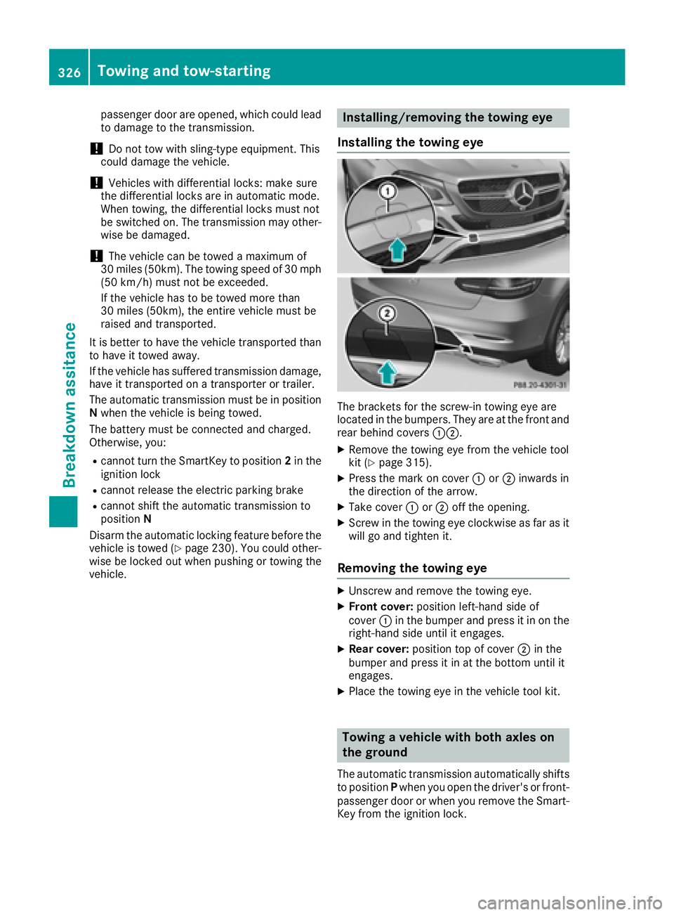
The brackets for the screw-in towing eye are
located in the bumpers. They are at the front and
rear behind covers :;.
XRemove the towing eye from the vehicle tool
kit (Ypage 315).
XPress the mark on cover :or; inwards in
the direction of the arrow.
XTake cover :or; off the opening.
XScrew in the towing eye clockwise as far as it
will go and tighten it.
Removing the towing eye
XUnscrew and remove the towing eye.
XFront cover: position left-hand side of
cover :in the bumper and press it in on the
right-hand side until it engages.
XRear cover: position top of cover ;in the
bumper and press it in at the bottom until it
engages.
XPlace the towing eye in the vehicle tool kit.
Towing a vehicle with both axles on
the ground
The automatic transmission automatically shifts
to position Pwhen you open the driver's or front-
passenger door or when you remove the Smart-
Key from the ignition lock.
326Towing and tow-starting
Breakdown assitance
Page 332 of 382
Useful information
i
This Operator's Manual describes all models
and all standard and optional equipment of
your vehicle available at the time of publica-
tion of the Operator's Manual. Country-spe-
cific differences are possible. Please note
that your vehicle may not be equipped with all
features described. This also applies to
safety-related systems and functions.
iRead the information on qualified specialist
workshops (Ypage 26).
Important safety notes
GWARNING
If wheels and tires of the wrong size are used, the wheel brakes or suspension components
may be damaged. There is a risk of an acci-
dent.
Always replace wheels and tires with those
that fulfill the specifications of the original
part.
When replacing wheels, make sure to use the
correct:
Rdesignation
Rmodel
When replacing tires, make sure to use the
correct:
Rdesignation
Rmanufacturer
Rmodel
GWARNING
A flat tire severely impairs the driving, steer-
ing and braking characteristics of the vehicle.
There is a risk of accident.
Tires without run-flat characteristics:
Rdo not drive with a flat tire.
Rimmediately replace the flat tire with your
emergency spare wheel or spare wheel, or
consult a qualified specialist workshop.
Tires with run-flat characteristics:
Rpay attention to the information and warn-
ing notices on MOExtended tires (tires with
run-flat characteristics).
Accessories that are not approved for your vehi-
cle by Mercedes-Benz or are not being used cor-
rectly can impair the operating safety.
Before purchasing and using non-approved
accessories, visit a qualified specialist work-
shop and inquire about:
Rsuitability
Rlegal stipulations
Rfactory recommendations
Information on the sizes and types of wheels and
tires for your vehicle can be found under
"Wheel/tire combinations" (
Ypage 356).
Tire pressure information can be found:
Ron the Tire and Loading Information placard
on the B-pillar on the driver's side
Rin the tire pressure table in the fuel filler flap
Rin the "Tire pressure" section
Operation
Information on driving
Check the tire pressure when the vehicle is
heavily laden and adjust prior to a trip.
While driving, pay attention to vibrations, noises and unusual handling characteristics, e.g. pull-
ing to one side. This may indicate that the
wheels or tires are damaged. If you suspect that
a tire is defective, reduce your speed immedi-
ately. Stop the vehicle as soon as possible to
check the wheels and tires for damage. Hidden
tire damage could also be causing the unusual
handling characteristics. If you find no signs of
damage, have the tires and wheels checked at a
qualified specialist workshop.
When parking your vehicle, make sure that the
tires do not get deformed by the curb or other
obstacles. If it is necessary to drive over curbs,
speed humps or similar elevations, try to do so
slowly and at an obtuse angle. Otherwise, the
tires, particularly the sidewalls, may be dam-
aged.
330Operation
Wheels and tires
Page 333 of 382
Regular checking of wheels and tires
GWARNING
Damaged tires can cause tire inflation pres-
sure loss. As a result, you could lose control of
your vehicle. There is a risk of accident.
Check the tires regularly for signs of damage
and replace any damaged tires immediately.
Check wheels and tires for damage at least once
a month. Check wheels and tires after driving
off-road or on rough roads. Damaged wheels
can cause a loss of tire pressure. Pay particular
attention to damage such as:
Rcuts in the tires
Rpunctures
Rtears in the tires
Rbulges on tires
Rdeformation or severe corrosion on wheels
Regularly check the tire tread depth and the
condition of the tread across the whole width of
the tire (
Ypage 331). If necessary, turn the
front wheels to full lock in order to inspect the
inner side of the tire surface.
All wheels must have a valve cap to protect the
valve against dirt and moisture. Do not mount
anything onto the valve other than the standard
valve cap or other valve caps approved by
Mercedes-Benz for your vehicle. Do not use any
other valve caps or systems, e.g. tire pressure
monitoring systems.
Regularly check the pressure of all the tires par-
ticularly prior to long trips. Adjust the tire pres-
sure as necessary (
Ypage 333).
Observe the notes on the emerge ncy sp
are
wheel (Ypage 360).
The service life of tires depends, among other
things, on the following factors:
Rdriving style
Rtire pressure
Rdistance covered
Notes on tire tread
GWARNING
Insufficient tire tread will reduce tire traction.
The tire is no longer able to dissipate water.
This means that on wet road surfaces, the risk
of hydroplaning increases, in particular where speed is not adapted to suit the driving con-
ditions. There is a risk of accident.
If the tire pressure is too high or too low, tires
may exhibit different levels of wear at differ-
ent locations on the tire tread. Thus, you
should regularly check the tread depth and
the condition of the tread across the entire
width of all tires.
Minimum tire tread depth for:
RSummer tires: âin (3 mm)
RM+S tires: ãin (4 mm)
For safety reasons, replace the tires before
the legally prescribed limit for the minimum
tire tread depth is reached.
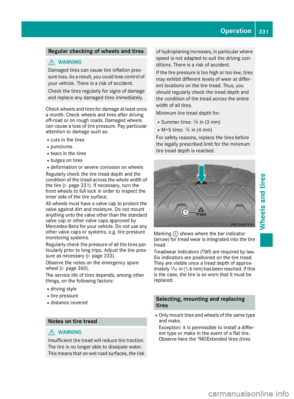
Marking :shows where the bar indicator
(arrow) for tread wear is integrated into the tire
tread.
Treadwear indicators (TWI) are required by law. Six indicators are positioned on the tire tread.
They are visible once a tread depth of approx-
imately áin (1.6 mm) has been reached. If this
is the case, the tire is so worn that it must be
replaced.
Selecting, mounting and replacing
tires
ROnly mount tires and wheels of the same type
and make.
Exception: it is permissible to install a differ-
ent type or make in the event of a flat tire.
Observe here the "MOExtended tires (tires
Operation331
Wheels and tires
Z