2016 MERCEDES-BENZ GLE-CLASS COUPE clock
[x] Cancel search: clockPage 221 of 382

Useful information
i
This Operator's Manual describes all models
and all standard and optional equipment of
your vehicle available at the time of publica-
tion of the Operator's Manual. Country-spe-
cific differences are possible. Please note
that your vehicle may not be equipped with all
features described. This also applies to
safety-related systems and functions.
iRead the information on qualified specialist
workshops (Ypage 26).
Important safety notes
GWARNING
If you operate information systems and com-
munication equipment integrated in the vehi-
cle while driving, you will be distracted from
traffic conditions. You could also lose control
of the vehicle. There is a risk of an accident.
Only operate the equipment when the traffic
situation permits. If you are not sure that this
is possible, park the vehicle paying attention
to traffic conditions and operate the equip-
ment when the vehicle is stationary.
You must observe the legal requirements for the
country in which you are currently driving when
operating the on-board computer.
GWARNING
If the instrument cluster has failed or mal-
functioned, you may not recognize function
restrictions in systems relevant to safety. The
operating safety of your vehicle may be
impaired. There is a risk of an accident.
Drive on carefully. Have the vehicle checked
at a qualified specialist workshop immedi-
ately.
If the operating safety of your vehicle is
impaired, pull over as soon as it is safe to do so.
Contact a qualified specialist workshop.
The on-board computer only shows messages or
warnings from certain systems in the multifunc-
tion display. You should therefore make sure
your vehicle is operating safely at all times. For an overview, see the instrument panel illus-
tration (
Ypage 31).
Displays and operation
Instrument cluster lighting
The lighting in the instrument cluster, in the dis-
plays and the controls in the vehicle interior can
be adjusted using the brightness control knob.
The brightness control knob is located on the
bottom left of the instrument cluster
(
Ypage 31).
XTurn the brightness control knob clockwise or
counter-clockwise.
If you turn the light switch to Ã,Tor
L, the brightness is dependent upon the
brightness of the ambient light.
iThe light sensor in the instrument cluster
automatically controls the brightness of the
multifunction display.
In daylight, the displays in the instrument
cluster are not illuminated.
Speedometer with segments
The speedometer is divided into segments only
on vehicles with DISTRONIC PLUS.
The segments in the speedometer indicate
which speed range is available.
RDISTRONIC PLUS activated (Ypage 170):
One or two segments in the set speed range
light up.
RDISTRONIC PLUS detects a vehicle in front
that is driving at a slower speed than the
stored speed:
The segments between the speed of the vehi- cle in front and the stored speed light up.
Tachometer
!
Do not drive in the overrevving range, as this
could damage the engine.
The red band in the tachometer indicates the
engine's overrevving range.
The fuel supply is interrupted to protect the
engine when the red band is reached.
Displays and operation219
On-board computer and displays
Z
Page 232 of 382
XPressato confirm.
XPress :or9 to select the DaytimeRunning Lightsfunction.
If the DaytimeRunningLightsfunction has
been switched on, the cone of light and the
W symbol in the multifunction display are
shown in orange.
XPress the abutton to save the setting.
Further information on daytime running lamps
(
Ypage 108).
Vehicle submenu
Activating/deactivating the automatic
door locking mechanism
If you activate the AutomaticDoorLockfunc-
tion, the vehicle is centrally locked above a
speed of approximately 9 mph (15 km/ h).
XPress the =or; button on the steering
wheel to select the Sett.menu.
XPress the:or9 button to select the
Vehiclesubmenu.
XPress ato confirm.
XPress the :or9 button to select the
Automatic Door Lockfunction.
When the Automatic Door Lockfunction is
activated, the vehicle doors are displayed in
orange in the multifunction display.
XPress the abutton to save the setting.
For further information on the automatic locking feature, see (
Ypage 79).
Activating/deactivating the acoustic
locking verification signal
If you switch on the AcousticLockfunction, an
acoustic signal sounds when you lock the vehi-
cle.
XPress the =or; button on the steering
wheel to select the Settingsmenu.
XPress the:or9 button to select the
Vehiclesubmenu.
XPress ato confirm.
XPress the :or9 button to select the
Acoustic Lockfunction.
If the Acoustic Lockfunction is activated,
the & symbol in the multifunction display
lights up orange.
XPress the abutton to save the setting.
Convenience submenu
Activating/deactivating the EASY-
ENTRY/EXIT feature
GWARNING
When the EASY-ENTRY/EXIT feature adjusts
the steering wheel, you and other vehicle
occupants – particularly children – could
become trapped. There is a risk of injury.
While the EASY-ENTRY/EXIT feature is mak-
ing adjustments, make sure that no one has
any body parts in the sweep of the steering
wheel.
If somebody becomes trapped:
Rpress one of the memory function position
buttons, or
Rmove the switch for steering wheel adjust-
ment in the opposite direction to that in
which the steering wheel is moving.
The adjustment process is stopped.
XPress the =or; button on the steering
wheel to select the Sett.menu.
XPress the:or9 button to select the
Conveniencesubmenu.
XPress ato confirm.
XUsing :or9, select the EasyEntry/Exitfunction.
If the EasyEntry/Exitfunction is activated,
the vehicle steering wheel is displayed in
orange in the multifunction display.
XPress the abutton to save the setting.
Further information on the EASY-ENTRY/EXIT
feature (
Ypage 103).
Switching the belt adjustment on/off
XPress the =or; button on the steering
wheel to select the Settingsmenu.
XPress the:or9 button to select the
Conveniencesubmenu.
XPress ato confirm.
XPress the :or9 button to select the
Belt Adjustmentfunction.
If the BeltAdjustmentfunction is activated,
the vehicle seat belt is shown in orange in the
multifunction display.
XPress the abutton to save the setting.
230Menus and submenus
On-board computer and displays
Page 307 of 382
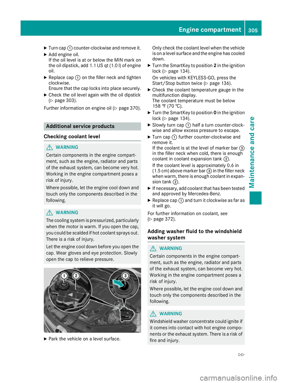
XTurn cap:counter-clockwise and remove it.
XAdd engine oil.
If the oil level is at or below the MIN mark on
the oil dipstick, add 1.1 US qt (1.0 l)of engine
oil.
XReplace cap :on the filler neck and tighten
clockwise.
Ensure that the cap locks into place securely.
XCheck the oil level again with the oil dipstick
(Ypage 303).
Further information on engine oil (
Ypage 370).
Additional service products
Checking coolant level
GWARNING
Certain components in the engine compart-
ment, such as the engine, radiator and parts
of the exhaust system, can become very hot.
Working in the engine compartment poses a
risk of injury.
Where possible, let the engine cool down and touch only the components described in the
following.
GWARNING
The cooling system is pressurized, particularly
when the motor is warm. If you open the cap,
you could be scalded if hot coolant sprays out.
There is a risk of injury.
Let the engine cool down before you open the
cap. Wear gloves and eye protection. Slowly
open the cap to relieve pressure.
XPark the vehicle on a level surface. Only check the coolant level when the vehicle
is on a level surface and the engine has cooled
down.
XTurn the SmartKey to position 2in the ignition
lock (Ypage 134).
On vehicles with KEYLESS-GO, press the
Start/Stop button twice (
Ypage 136).
XCheck the coolant temperature gauge in the
multifunction display.
The coolant temperature must be below
158 ‡ (70 †).
XTurn the SmartKey to position 0in the ignition
lock (Ypage 134).
XSlowly turn cap :half a turn counter-clock-
wise and allow excess pressure to escape.
XTurn cap :further counter-clockwise and
remove it.
If the coolant is at the level of marker bar =
in the filler neck when cold, there is enough
coolant in coolant expansion tank ;.
If the coolant level is approximately 0.6 in
(1.5 cm) above marker bar =in the filler neck
when warm, there is enough coolant in expan-
sion tank ;.
XIf necessary, add coolant that has been tested
and approved by Mercedes-Benz.
XReplace cap :and turn it clockwise as far as
it will go.
For further information on coolant, see
(
Ypage 372).
Adding washer fluid to the windshield
washer system
GWARNING
Certain components in the engine compart-
ment, such as the engine, radiator and parts
of the exhaust system, can become very hot.
Working in the engine compartment poses a
risk of injury.
Where possible, let the engine cool down and touch only the components described in the
following.
GWARNING
Windshield washer concentrate could ignite if it comes into contact with hot engine compo-
nents or the exhaust system. There is a risk of
fire and injury.
Engine compartment305
Maintenance and care
Z
Page 324 of 382
The vehicle will then use very little energy, thus
conserving battery power.
If the power supply has been interrupted, e.g. ifyou reconnect the battery, you will have to:
Rset the clock. Information on setting the clock
can be found in the Digital Operator's Manual.
On vehicles with a multimedia system and
navigation system, the clock is set automati-
cally.
Rreset the function for folding the exterior mir-
rors in/out automatically, by folding the mir-
rors out once (
Ypage 105).
Charging the 12 V battery
GWARNING
During charging and jump-starting, explosive
gases can escape from the battery. There is a risk of an explosion.
Particularly avoid fire, open flames, creating
sparks and smoking. Ensure there is sufficient
ventilation while charging and jump-starting.
Do not lean over a battery.
GWARNING
Battery acid is caustic. There is a risk of injury.
Avoid contact with skin, eyes or clothing. Do
not inhale any battery gases. Do not lean over
the battery. Keep children away from batter-
ies. Wash away battery acid immediately with
plenty of clean water and seek medical atten-
tion.
GWARNING
A discharged battery can freeze at tempera-
tures below freezing point. When jump-start-
ing the vehicle or charging the battery, gases can escape from the battery. There is a risk of
an explosion.
Allow the frozen battery to thaw out before
charging it or jump-starting.
!Only use battery chargers with a maximum
charging voltage of 14.8 V.
!Only charge the battery using the jump-
starting connection point. The jump-starting connection point is in the
engine compartment (
Ypage 323).
XOpen the hood.
XConnect the battery charger to the positive
terminal and ground point in the same order
as when connecting the donor battery in the
jump-starting procedure (
Ypage 323).
Keep away from fire and open flames. Do not
lean over a battery. Never charge the battery if it
is still installed in the vehicle, unless you use a
battery charger which has been tested and
approved by Mercedes-Benz. A battery charger
unit specially adapted for Mercedes-Benz vehi-
cles and tested and approved by Mercedes-
Benz is available as an accessory. It permits the
charging of the battery in its installed position.
Contact an authorized Mercedes-Benz Center
for further information and availability. Read the
battery charger's operating instructions before
charging the battery.
If, at low temperatures, the indicator lamps/
warning lamps in the instrument cluster do not
light up, it is highly likely that the discharged
battery has frozen. In this case you may neither
jump-start the vehicle nor charge the battery.
The service life of a thawed-out battery may be
shorter. The starting characteristics can be
impaired, particularly at low temperatures. Have
the thawed-out battery checked at a qualified
specialist workshop.
322Battery (vehicle)
Breakdown assitance
Page 328 of 382
passenger door are opened, which could lead
to damage to the transmission.
!Do not tow with sling-type equipment. This
could damage the vehicle.
!Vehicles with differential locks: make sure
the differential locks are in automatic mode.
When towing, the differential locks must not
be switched on. The transmission may other- wise be damaged.
!The vehicle can be towed a maximum of
30 miles (50km). The towing speed of 30 mph
(50 km/h) must not be exceeded.
If the vehicle has to be towed more than
30 miles (50km), the entire vehicle must be
raised and transported.
It is better to have the vehicle transported than
to have it towed away.
If the vehicle has suffered transmission damage,
have it transported on a transporter or trailer.
The automatic transmission must be in position
N when the vehicle is being towed.
The battery must be connected and charged.
Otherwise, you:
Rcannot turn the SmartKey to position 2in the
ignition lock
Rcannot release the electric parking brake
Rcannot shift the automatic transmission to
position N
Disarm the automatic locking feature before the vehicle is towed (
Ypage 230). You could other-
wise be locked out when pushing or towing the
vehicle.
Installing/removing the towing eye
Installing the towing eye
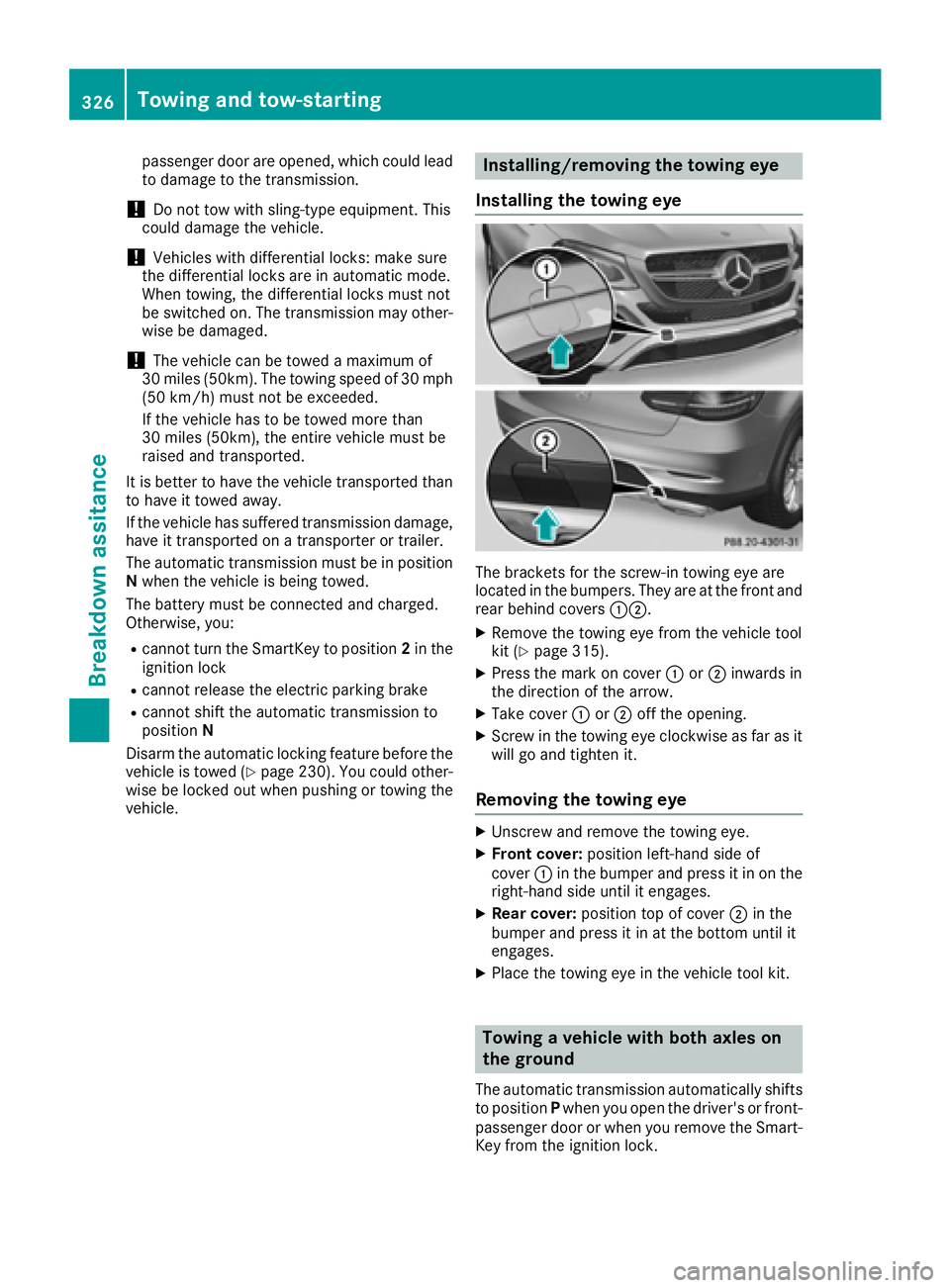
The brackets for the screw-in towing eye are
located in the bumpers. They are at the front and
rear behind covers :;.
XRemove the towing eye from the vehicle tool
kit (Ypage 315).
XPress the mark on cover :or; inwards in
the direction of the arrow.
XTake cover :or; off the opening.
XScrew in the towing eye clockwise as far as it
will go and tighten it.
Removing the towing eye
XUnscrew and remove the towing eye.
XFront cover: position left-hand side of
cover :in the bumper and press it in on the
right-hand side until it engages.
XRear cover: position top of cover ;in the
bumper and press it in at the bottom until it
engages.
XPlace the towing eye in the vehicle tool kit.
Towing a vehicle with both axles on
the ground
The automatic transmission automatically shifts
to position Pwhen you open the driver's or front-
passenger door or when you remove the Smart-
Key from the ignition lock.
326Towing and tow-starting
Breakdown assitance
Page 363 of 382

Replaceth etires after six years at th elatest ,
regardless of wear .This also applie sto th e
emergenc yspar ewheel.
iWhen you are driving wit hth ecollapsible
spar ewhee lmounted, th etire pressur eloss
warning system or th etire pressur emonitor
canno tfunction reliably. Only restar tth etire
pressur eloss warning system or tire pressur e
monitor when th edefective whee lhas been
replace dwit h a newwheel.
Vehicles with tire pressure monitor: after
mounting an emergenc yspar ewheel, th esys-
te m may still display th etire pressur eof th e
remove dwhee lfor afew minutes. The value
displayed for th emounte demergenc yspar e
whee lis no tth esam eas th ecurren ttire pres-
sur eof th eemergenc yspar ewheel.
Removing/stowing the emergency
spare wheel
Vehicles with a "Minispare" emergency
spare wheel under the cargo compart-
ment floor
Always observ eth einstruction sand safet y
note sin th e"Mounting awheel" section
(
Ypage 352).
The "Minispare" emergenc yspar ewhee lcan be
foun din th estowage well under th ecargo com-
partmen tfloor.
Removin gth eemergenc yspar ewhee l
XLiftth ecargo compartmen tfloor upwards
(Ypage 284).
XTurn retaining screw ;counter-clockwise
and remove it .
XRemove "Minispare" emergenc yspar e
whee l:.
Vehicles with a "Minispare" emergency
spare wheel in the emergency spare
wheel bag
Always observ eth einstruction sand safet y
note sin th e"Mounting awheel" section
(
Ypage 352).
On vehicles wit h aBan g & Olufsen soun dsys-
tem, th e"Minispare" emergenc yspar ewhee lis
packe din an emergenc yspar ewhee lbag. The
emergenc yspar ewhee lbag is secured to th e
cargo tie-down rings in th ecargo compartment.
Removin gth eemergenc yspar ewhee l
XDetac hfastenin gstraps ;.
XUnhookretaining spring hooks :and =of
fastenin gstraps ;from th ecargo tie-down
rings.
XRemove th eemergenc yspar ewhee lbag wit h
th e"Minispare" emergenc yspar ewheel.
XOpen th eemergenc yspar ewhee lbag and
remove th e"Minispare" emergenc yspar e
wheel.
Stowin gth eemergenc yspar ewhee l
XPlaceth e"Minispare" emergenc yspar ewhee l
int oth eemergenc yspar ewhee lbag and
close th eemergenc yspar ewhee lbag.
XPlac eth eemergenc yspar ewhee lbag wit h
th e"Minispare" emergenc yspar ewhee lint o
th ecargo compartmen twit hth ecarryin g
strap at th eback.
XHook retaining spring hooks :and =of
fastenin gstraps ;intoth ecargo tie-down
rings.
XTighte nfastenin gstraps ;.
Emergency spare wheel361
Wheels and tires
Z
Page 364 of 382
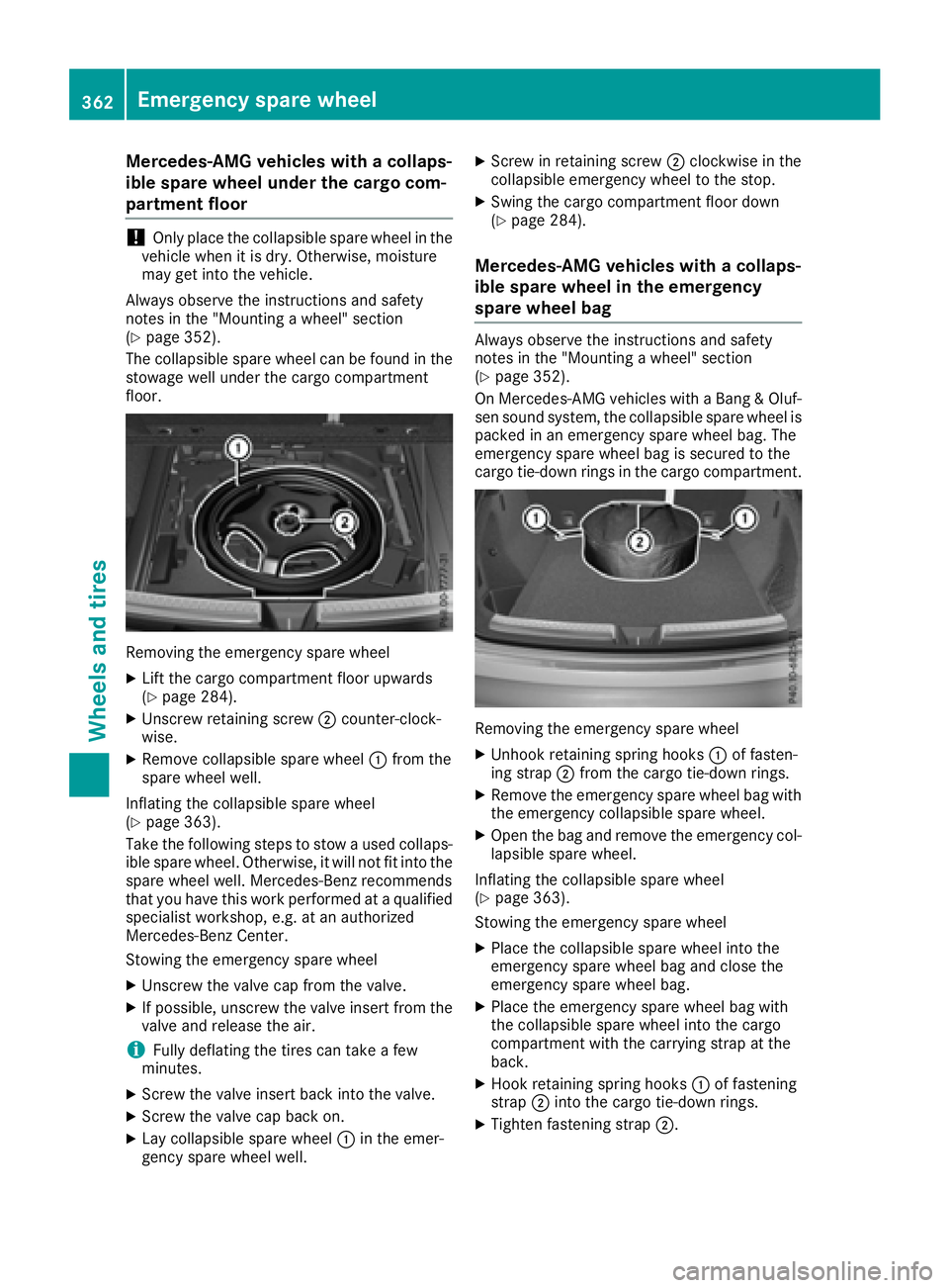
Mercedes-AMG vehicles with a collaps-
ible spare wheel under the cargo com-
partment floor
!Only place the collapsible spare wheel in the
vehicle when it is dry. Otherwise, moisture
may get into the vehicle.
Always observe the instructions and safety
notes in the "Mounting a wheel" section
(
Ypage 352).
The collapsible spare wheel can be found in the
stowage well under the cargo compartment
floor.
Removing the emergency spare wheel
XLift the cargo compartment floor upwards
(Ypage 284).
XUnscrew retaining screw ;counter-clock-
wise.
XRemove collapsible spare wheel :from the
spare wheel well.
Inflating the collapsible spare wheel
(
Ypage 363).
Take the following steps to stow a used collaps- ible spare wheel. Otherwise, it will not fit into the
spare wheel well. Mercedes-Benz recommends
that you have this work performed at a qualified
specialist workshop, e.g. at an authorized
Mercedes-Benz Center.
Stowing the emergency spare wheel
XUnscrew the valve cap from the valve.
XIf possible, unscrew the valve insert from the
valve and release the air.
iFully deflating the tires can take a few
minutes.
XScrew the valve insert back into the valve.
XScrew the valve cap back on.
XLay collapsible spare wheel :in the emer-
gency spare wheel well.
XScrew in retaining screw ;clockwise in the
collapsible emergency wheel to the stop.
XSwing the cargo compartment floor down
(Ypage 284).
Mercedes-AMG vehicles with a collaps-
ible spare wheel in the emergency
spare wheel bag
Always observe the instructions and safety
notes in the "Mounting a wheel" section
(
Ypage 352).
On Mercedes-AMG vehicles with a Bang & Oluf-
sen sound system, the collapsible spare wheel is packed in an emergency spare wheel bag. The
emergency spare wheel bag is secured to the
cargo tie-down rings in the cargo compartment.
Removing the emergency spare wheel
XUnhook retaining spring hooks :of fasten-
ing strap ;from the cargo tie-down rings.
XRemove the emergency spare wheel bag with
the emergency collapsible spare wheel.
XOpen the bag and remove the emergency col-
lapsible spare wheel.
Inflating the collapsible spare wheel
(
Ypage 363).
Stowing the emergency spare wheel
XPlace the collapsible spare wheel into the
emergency spare wheel bag and close the
emergency spare wheel bag.
XPlace the emergency spare wheel bag with
the collapsible spare wheel into the cargo
compartment with the carrying strap at the
back.
XHook retaining spring hooks :of fastening
strap ;into the cargo tie-down rings.
XTighten fastening strap ;.
362Emergency spare wheel
Wheels and tires