2016 MERCEDES-BENZ GLE-CLASS COUPE lock
[x] Cancel search: lockPage 190 of 382

Warning displays
:Segments on the left-hand side of the vehi-
cle
;Segments on the right-hand side of the vehi-cle
=Segments showing operational readiness
The warning displays show the distance
between the sensors and the obstacle. The
warning display for the front area is located on
the dashboard above the center air vents. The
warning display for the rear area is located on
the headliner in the rear compartment.
The warning display for each side of the vehicle
is divided into five yellow and two red segments.
PARKTRONIC is operational if yellow segments
showing operational readiness =light up.
The selected transmission position and the
direction in which the vehicle is rolling deter-
mine which warning display is active when the
engine is running.
Transmission posi-
tionWarning display
DFront area activated
R, Nor the vehicle is
rolling backwardsRear and front areas
activated
PNo areas activated
One or more segments light up as the vehicle
approaches an obstacle, depending on the vehi-
cle's distance from the obstacle.
From the:
Rsixth segment onwards, you will hear an inter-
mittent warning tone for approximately two
seconds.
Rseventh segment onwards, you will hear a
warning tone for approximately two seconds. This indicates that you have now reached the
minimum distance.
Deactivating/activating PARKTRONIC
:Indicator lamp
;To deactivate/activate PARKTRONIC
If indicator lamp :is on then PARKTRONIC is
deactivated. Active Parking Assist is then also
deactivated.
iPARKTRONIC is automatically activated
when you turn the SmartKey to position 2in
the ignition lock.
188Driving systems
Driving and parking
Page 192 of 382

RSnowfall or heavy rain may lead to a parking
space being measured inaccurately.
RPay attention to the PARKTRONIC
(Ypage 188) warning messages during the
parking procedure.
RAt any time, you can intervene in the steering procedure to correct it. Active Parking Assist
will then be canceled.
RWhen transporting a load which protrudes
from your vehicle, you should not use Active
Parking Assist.
RNever use Active Parking Assist when snow
chains are installed.
RMake sure that the tire pressures are always
correct. This has a direct influence on the
parking characteristics of the vehicle.
Use Active Parking Assist for parking spaces:
Rparallel or at right angles to the direction of
travel
Rthat are on straight roads, not bends
Rthat are on the same level as the road, e.g. not
on the pavement
Detecting parking spaces
Objects located above the height range of Active Parking Assist will not be detected when the
parking space is measured. These are not taken
into account when the parking procedure is cal-
culated, e.g. overhanging loads, tail sections or
loading ramps of goods vehicles.
GWARNING
If there are objects above the detection range:
RActive Park Assist may steer too early
Rthe vehicle may not stop in front of these
objects
You may cause a collision as a result. There is
a risk of an accident.
If objects are located above the detection
range, stop and deactivate Active Parking
Assist.
For further information on the detection range
(
Ypage 187). Active Parking Assist does not assist you park-
ing in spaces at right angles to the direction of
travel if:
Rtwo parking spaces are located directly next
to one another
Rthe parking space is directly next to a low
obstacle such as a low curb
Ryou park forwards
Active Parking Assist does not assist you park-
ing in spaces that are parallel or at right angles
to the direction of travel if:
Rthe parking space is on a curb
Rthe system reads the parking space as being
blocked, for example by foliage or grass pav-
ing blocks
Rthe area is too small for the vehicle to maneu-
ver into
Rthe parking space is bordered by an obstacle,
e.g. a tree, a post or a trailer
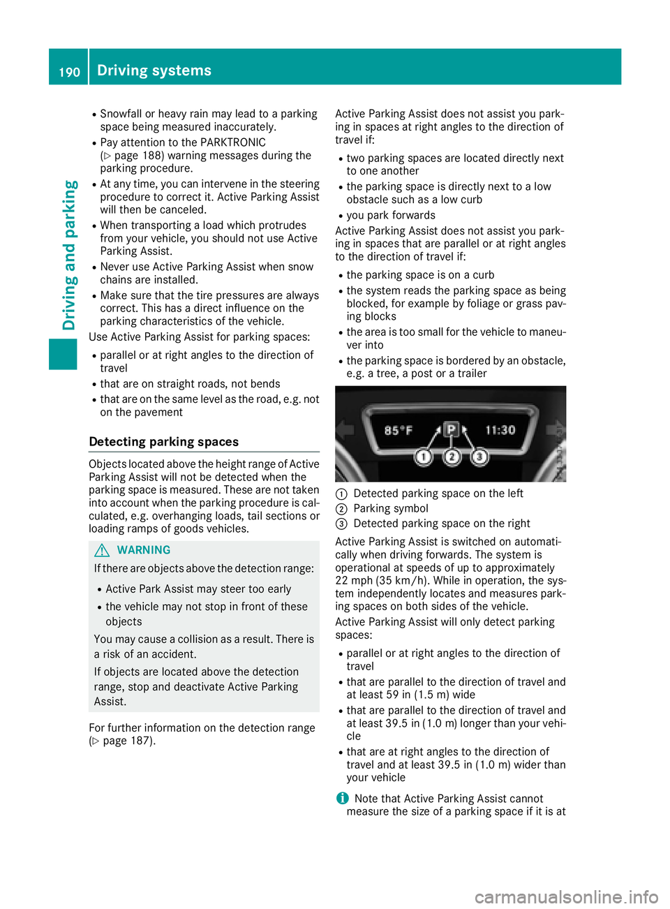
:Detected parking space on the left
;Parking symbol
=Detected parking space on the right
Active Parking Assist is switched on automati-
cally when driving forwards. The system is
operational at speeds of up to approximately
22 mph (35 km/h). While in operation, the sys-
tem independently locates and measures park-
ing spaces on both sides of the vehicle.
Active Parking Assist will only detect parking
spaces:
Rparallel or at right angles to the direction of
travel
Rthat are parallel to the direction of travel and
at least 59 in (1.5 m) wide
Rthat are parallel to the direction of travel and
at least 39.5 in (1.0 m)longer than your vehi-
cle
Rthat are at right angles to the direction of
travel and at least 39.5 in (1.0 m) wider than
your vehicle
iNote that Active Parking Assist cannot
measure the size of a parking space if it is at
190Driving systems
Driving and parking
Page 196 of 382

The emblem closes again when:
Ryou have finished the maneuvering process
Ryou switch off the engine
Ryou open the trunk
Observe the notes on cleaning (
Ypage 311).
For technical reasons, the emblem may
remain open briefly after the rear view camera
has been deactivated.
Activating/deactivating the rear view
camera
XTo activate: make sure that the SmartKey is
in position 2in the ignition lock.
XMake sure that the Activation by R gearfunction is selected in the multimedia system;
see the Digital Operator's Manual.
XEngage reverse gear.
The rear view camera flap opens. The multi-
media system shows the area behind the vehi-
cle with guide lines.
The image from the rear view camera is avail-
able throughout the maneuvering process.
To deactivate: the rear view camera deacti-
vates if you shift the transmission to Por after
driving forwards a short distance.
Displays in the multimedia system
The rear view camera may show a distorted view
of obstacles, show them incorrectly or not at all.
The rear view camera does not show objects in
the following positions:
Rvery close to the rear bumper
Runder the rear bumper
Rin the area immediately above the tailgate
handle
!Objects not at ground level may appear to
be further away than they actually are, e.g.:
Rthe bumper of a parked vehicle
Rthe drawbar of a trailer
Rthe ball coupling of a trailer tow hitch
Rthe rear section of an HGV
Ra slanted post
Use the guidelines only for orientation.
Approach objects no further than the bottom-
most guideline.
:Yellow guide line at a distance of approx-
imately 13 ft (4.0 m) from the rear of the
vehicle
;White guide line without turning the steering
wheel, vehicle width including the exterior
mirrors (static)
=Yellow guide line for the vehicle width
including the exterior mirrors, for current
steering wheel angle (dynamic)
?Yellow lane marking tires at current steering
wheel angle (dynamic)
AYellow guide line at a distance of approx-
imately 3 ft (1.0 m) from the rear of the vehi-
cle
BVehicle center axle (marker assistance)
CBumper
DRed guide line at a distance of approximately
12 in (0.30 m) from the rear of the vehicle
The guide lines are shown when the transmis-
sion is in position R.
The distance specifications only apply to
objects that are at ground level.
194Driving systems
Driving and parking
Page 200 of 382

Rif there is a sudden change in temperature,
e.g. when driving into a heated garage in win-ter
Rif the camera lenses are dirty or covered
Rif the vehicle components in which the cam-
eras are installed are damaged. In this event,
have the camera position and setting checked
at a qualified specialist workshop
Do not use the 360° camera in this case. You
can otherwise injure others or cause damage to objects or the vehicle.
Guide lines are always shown at road level.
The field of vision and other functions of the
camera system may be restricted due to addi-
tional accessories on the rear of the vehicle (e.g.
license plate holder, bicycle rack).
On vehicles with height-adjustable chassis,
depending on technical conditions, leaving the
standard height can result in:
Rinaccuracies in the guide lines
Rinaccuracies in the display of generated
images (top view)
Activation conditions
The 360° camera image can be displayed if:
Ryour vehicle is equipped with a 360° camera
Rthe SmartKey is in position 2in the ignition
lock
Rthe multimedia system is switched on
Switching on the 360° camera
XPress the Øbutton in the center console
for longer than two seconds.
Depending on whether position Dor Ris
engaged, the following is shown:
Ra split screen with top view and the image
from the front camera or
Ra split screen with top view and the image
from the rear view camera
or
XPress the Øbutton in the center console.
The vehicle menu is displayed.
XSelect 360°Cameraand press 7to confirm.
Depending on whether position Dor Ris
engaged, the following is shown:
Ra split screen with top view and the image
from the front camera or
Ra split screen with top view and the image
from the rear view camera
Activating the 360° camera using
reverse gear
The 360° camera images can be automatically
displayed by engaging reverse gear.
XMake sure that the SmartKey is in position 2
in the ignition lock.
XMake sure that the Activation by R gearfunction is selected in the multimedia system
(see the separate operating instructions).
XTo show the 360° camera image: engage
reverse gear.
The multimedia system shows the area
behind the vehicle in split-screen mode. You
see the top view of the vehicle and the image
from the rear view camera.
Selecting the split-screens or 180° view
Selecting split-screen view
XTo switch to the line with the vehicle icons:
slide 5the controller.
XTo select one of the vehicle icons: turn 3
the controller.
XTo switch to 180° View:turn 3 the con-
troller to select 180° View
and press7to
confirm.
iThe 180°Viewoption is only available in the
following views:
RTop view with picture from the rear view
camera
RTop view with picture from the front camera
Displays in the multimedia system
Important safety notes
The camera system may show a distorted view
of obstacles, show them incorrectly or not at all.
Obstacles are not shown by the system in the
following locations:
Runder the front and rear bumpers
Rvery close to the front and rear bumpers
Rin the area immediately above the tailgate
handle
Rvery close to the exterior mirrors
Rin the transitional areas between the various
cameras in the virtual top view
198Driving systems
Driving and parking
Page 207 of 382

Switching on Blind Spot Assist
XMake sure that Blind Spot Assist is activated
in the on-board computer (Ypage 228).
XTurn the SmartKey to position2in the ignition
lock.
Warning lamps :in the exterior mirrors light
up red for approximately 1.5 seconds and
then turn yellow.
Towing a trailer
When you attach a trailer, make sure you have
correctly established the electrical connection.
This can be accomplished by checking the trailer
lighting. In this event, Blind Spot Assist is deac-
tivated. The indicator lamp lights up yellow in
the exterior mirrors and the Blind Spot
Assist Not Available When Towing aTrailer See Operator's Manualmessage
appears in the multifunction display.
iYou can deactivate the indicator lamps in
the exterior mirrors.
To do so, switch off Blind Spot Assist when:
Rthe SmartKey is in position 2in the ignition
lock
Rthe engine is not running
Lane Keeping Assist
General notes
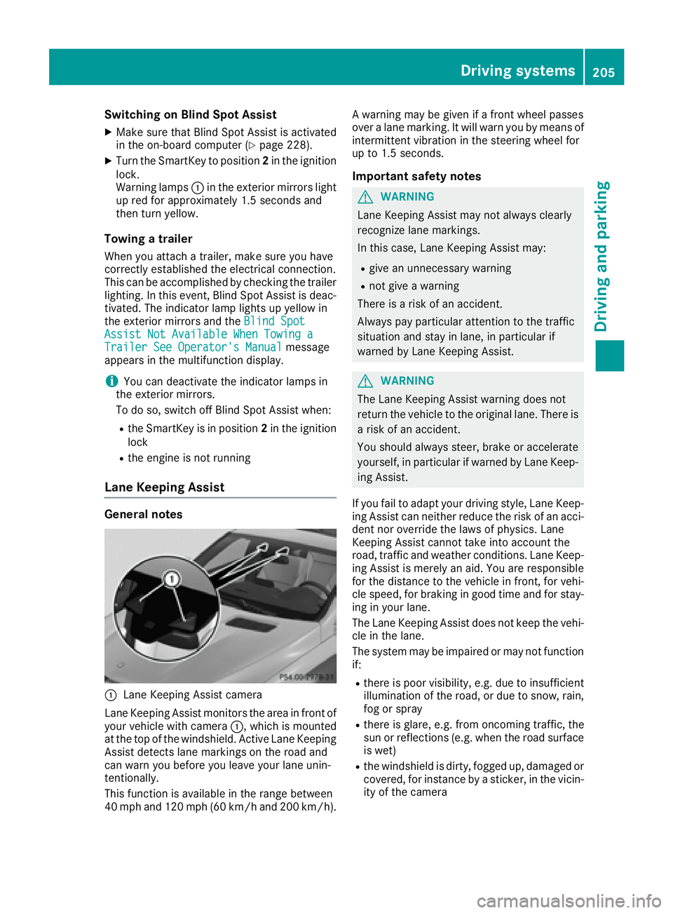
:Lane Keeping Assist camera
Lane Keeping Assist monitors the area in front of
your vehicle with camera :, which is mounted
at the top of the windshield. Active Lane Keeping
Assist detects lane markings on the road and
can warn you before you leave your lane unin-
tentionally.
This function is available in the range between
40 mph and 120 mph (60 km/h and 200 km/h). A warning may be given if a front wheel passes
over a lane marking. It will warn you by means of
intermittent vibration in the steering wheel for
up to 1.5 seconds.
Important safety notes
GWARNING
Lane Keeping Assist may not always clearly
recognize lane markings.
In this case, Lane Keeping Assist may:
Rgive an unnecessary warning
Rnot give a warning
There is a risk of an accident.
Always pay particular attention to the traffic
situation and stay in lane, in particular if
warned by Lane Keeping Assist.
GWARNING
The Lane Keeping Assist warning does not
return the vehicle to the original lane. There is
a risk of an accident.
You should always steer, brake or accelerate
yourself, in particular if warned by Lane Keep-
ing Assist.
If you fail to adapt your driving style, Lane Keep-
ing Assist can neither reduce the risk of an acci-
dent nor override the laws of physics. Lane
Keeping Assist cannot take into account the
road, traffic and weather conditions. Lane Keep- ing Assist is merely an aid. You are responsible
for the distance to the vehicle in front, for vehi-
cle speed, for braking in good time and for stay-
ing in your lane.
The Lane Keeping Assist does not keep the vehi-
cle in the lane.
The system may be impaired or may not function
if:
Rthere is poor visibility, e.g. due to insufficient
illumination of the road, or due to snow, rain,
fog or spray
Rthere is glare, e.g. from oncoming traffic, the
sun or reflections (e.g. when the road surface
is wet)
Rthe windshield is dirty, fogged up, damaged or
covered, for instance by a sticker, in the vicin-
ity of the camera
Driving systems205
Driving and parking
Z
Page 211 of 382

Either no braking application, or a course-cor-
recting brake application adapted to the driving
situation occurs if:
Rthere are vehicles or obstacles, e.g. crash
barriers, close to both sides of your vehicle.
Ra vehicle approaches you too closely at the
side.
Ryou have adopted a sporty driving style with
high cornering speeds.
Ryou brake or accelerate significantly.
Ra driving safety system intervenes, e.g. ESP®
or PRE-SAFE®Brake.
RESP®is switched off.
Ra loss of tire pressure or a defective tire is
detected.
Switching on Active Blind Spot Assist
XMake sure that Active Blind Spot Assist is
activated in the on-board computer
(
Ypage 228).
XTurn the SmartKey to position2in the ignition
lock.
Warning lamps :in the exterior mirrors light
up red for approximately 1.5 seconds and
then turn yellow.
Towing a trailer
When you attach a trailer, make sure you have
correctly established the electrical connection.
This can be accomplished by checking the trailer
lighting. Active Blind Spot Assist is then deacti-
vated. The indicator lamp lights up yellow in the
exterior mirrors and the Active Blind Spot
Asst. Not Available When Towing aTrailer See Operator's Manualmessage
appears in the multifunction display.
Active Lane Keeping Assist
General notes
Active Lane Keeping Assist monitors the area in
front of your vehicle by means of multifunction
camera :at the top of the windshield. Various
different areas to the front, rear and side of your
vehicle are also monitored with the aid of the
radar sensor system. Active Lane Keeping
Assist detects lane markings on the road and
can warn you before you leave your lane unin-
tentionally. If you do not react to the warning, a
lane-correcting application of the brakes can
bring the vehicle back into the original lane.
This function is available in a speed range
between 40 mph and 120 mph (60 km/h and
200 km/h).
For Active Lane Keeping Assist to assist you
when driving, the radar sensor system must be
operational.
Important safety notes
If you fail to adapt your driving style, Active Lane
Keeping Assist can neither reduce the risk of
accident nor override the laws of physics. Active
Lane Keeping Assist cannot take into account
road, weather or traffic conditions. Active Lane
Keeping Assist is only an aid. You are responsi-
ble for the distance to the vehicle in front, for
vehicle speed, for braking in good time and for
staying in your lane.
Active Lane Ke
eping Assist cannot continuously
keep your vehicle in its lane.
GWARNING
Active Lane Keeping Assist cannot always
clearly detect lane markings.
Driving system s209
Driving an d parking
Z
Page 217 of 382

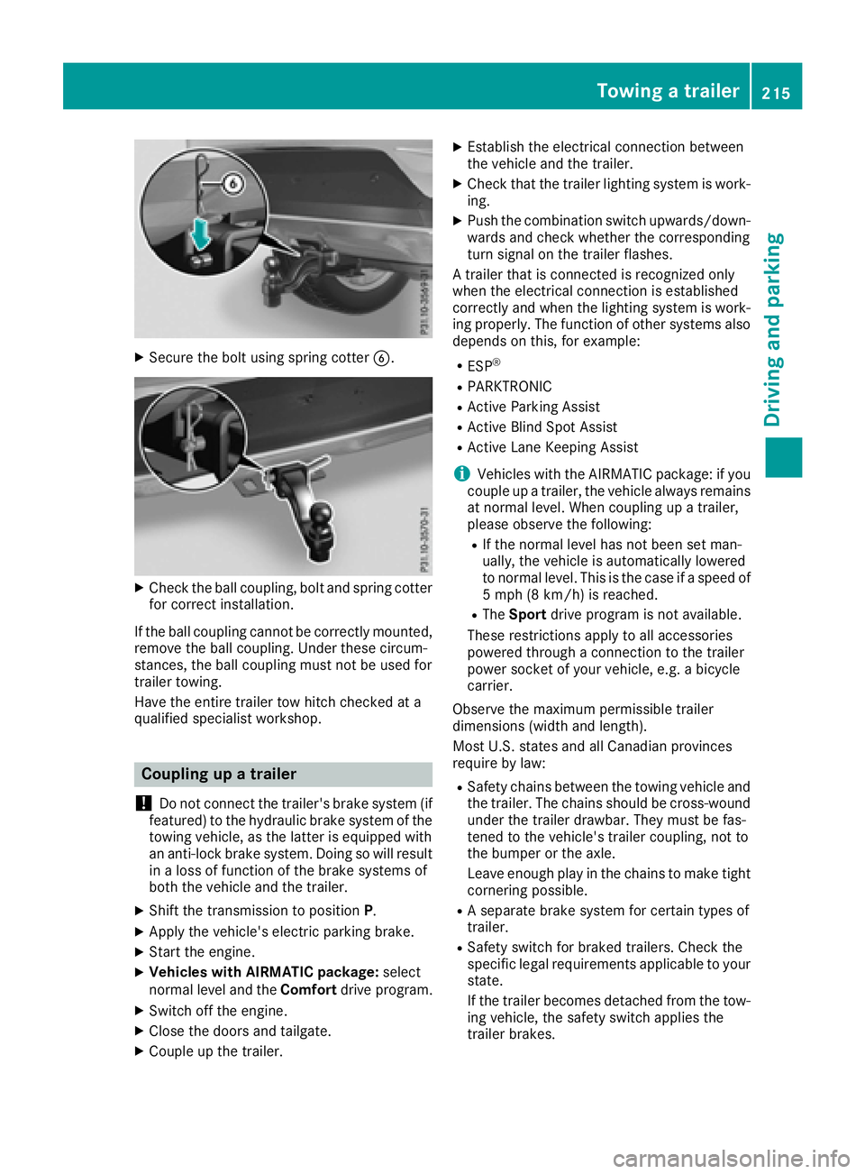
XSecure the bolt using spring cotterB.
XCheck the ball coupling, bolt and spring cotter
for correct installation.
If the ball coupling cannot be correctly mounted,
remove the ball coupling. Under these circum-
stances, the ball coupling must not be used for
trailer towing.
Have the entire trailer tow hitch checked at a
qualified specialist workshop.
Coupling up a trailer
!
Do not connect the trailer's brake system (if
featured) to the hydraulic brake system of the
towing vehicle, as the latter is equipped with
an anti-lock brake system. Doing so will result
in a loss of function of the brake systems of
both the vehicle and the trailer.
XShift the transmission to position P.
XApply the vehicle's electric parking brake.
XStart the engine.
XVehicles with AIRMATIC package: select
normal level and the Comfortdrive program.
XSwitch off the engine.
XClose the doors and tailgate.
XCouple up the trailer.
XEstablish the electrical connection between
the vehicle and the trailer.
XCheck that the trailer lighting system is work-
ing.
XPush the combination switch upwards/down-
wards and check whether the corresponding
turn signal on the trailer flashes.
A trailer that is connected is recognized only
when the electrical connection is established
correctly and when the lighting system is work-
ing properly. The function of other systems also
depends on this, for example:
RESP®
RPARKTRONIC
RActive Parking Assist
RActive Blind Spot Assist
RActive Lane Keeping Assist
iVehicles with the AIRMATIC package: if you
couple up a trailer, the vehicle always remains
at normal level. When coupling up a trailer,
please observe the following:
RIf the normal level has not been set man-
ually, the vehicle is automatically lowered
to normal level. This is the case if a speed of
5 mph (8 km/h) is reached.
RThe Sport drive program is not available.
These restrictions apply to all accessories
powered through a connection to the trailer
power socket of your vehicle, e.g. a bicycle
carrier.
Observe the maximum permissible trailer
dimensions (width and length).
Most U.S. states and all Canadian provinces
require by law:
RSafety chains between the towing vehicle and
the trailer. The chains should be cross-wound
under the trailer drawbar. They must be fas-
tened to the vehicle's trailer coupling, not to
the bumper or the axle.
Leave enough play in the chains to make tight
cornering possible.
RA separate brake system for certain types of
trailer.
RSafety switch for braked trailers. Check the
specific legal requirements applicable to your
state.
If the trailer becomes detached from the tow-
ing vehicle, the safety switch applies the
trailer brakes.
Towing a trailer215
Driving and parking
Z
Page 221 of 382

Useful information
i
This Operator's Manual describes all models
and all standard and optional equipment of
your vehicle available at the time of publica-
tion of the Operator's Manual. Country-spe-
cific differences are possible. Please note
that your vehicle may not be equipped with all
features described. This also applies to
safety-related systems and functions.
iRead the information on qualified specialist
workshops (Ypage 26).
Important safety notes
GWARNING
If you operate information systems and com-
munication equipment integrated in the vehi-
cle while driving, you will be distracted from
traffic conditions. You could also lose control
of the vehicle. There is a risk of an accident.
Only operate the equipment when the traffic
situation permits. If you are not sure that this
is possible, park the vehicle paying attention
to traffic conditions and operate the equip-
ment when the vehicle is stationary.
You must observe the legal requirements for the
country in which you are currently driving when
operating the on-board computer.
GWARNING
If the instrument cluster has failed or mal-
functioned, you may not recognize function
restrictions in systems relevant to safety. The
operating safety of your vehicle may be
impaired. There is a risk of an accident.
Drive on carefully. Have the vehicle checked
at a qualified specialist workshop immedi-
ately.
If the operating safety of your vehicle is
impaired, pull over as soon as it is safe to do so.
Contact a qualified specialist workshop.
The on-board computer only shows messages or
warnings from certain systems in the multifunc-
tion display. You should therefore make sure
your vehicle is operating safely at all times. For an overview, see the instrument panel illus-
tration (
Ypage 31).
Displays and operation
Instrument cluster lighting
The lighting in the instrument cluster, in the dis-
plays and the controls in the vehicle interior can
be adjusted using the brightness control knob.
The brightness control knob is located on the
bottom left of the instrument cluster
(
Ypage 31).
XTurn the brightness control knob clockwise or
counter-clockwise.
If you turn the light switch to Ã,Tor
L, the brightness is dependent upon the
brightness of the ambient light.
iThe light sensor in the instrument cluster
automatically controls the brightness of the
multifunction display.
In daylight, the displays in the instrument
cluster are not illuminated.
Speedometer with segments
The speedometer is divided into segments only
on vehicles with DISTRONIC PLUS.
The segments in the speedometer indicate
which speed range is available.
RDISTRONIC PLUS activated (Ypage 170):
One or two segments in the set speed range
light up.
RDISTRONIC PLUS detects a vehicle in front
that is driving at a slower speed than the
stored speed:
The segments between the speed of the vehi- cle in front and the stored speed light up.
Tachometer
!
Do not drive in the overrevving range, as this
could damage the engine.
The red band in the tachometer indicates the
engine's overrevving range.
The fuel supply is interrupted to protect the
engine when the red band is reached.
Displays and operation219
On-board computer and displays
Z