2016 MERCEDES-BENZ GLE-CLASS COUPE engine
[x] Cancel search: enginePage 215 of 382
RThe bumpers of your vehicle are not suitable
for installing detachable trailer couplings.
RDo not install hired trailer couplings or other
detachable trailer couplings on the bumpers
of your vehicle.
RIf you no longer need the ball coupling,
remove it from the ball coupling recess. This
will reduce the risk of damage to the ball cou-
pling.
When towing a trailer, set the tire pressure on
the rear axle of the towing vehicle for the max-
imum load. You will find the values in the tire
pressure table in the fuel filler flap of the vehicle
(
Ypage 349).
Please note that when towing a trailer, the fol-
lowing driving systems have limited availability
or are not available at all:
RPARKTRONIC (Ypage 186)
RBlind Spot Assist (Ypage 203)
RActive Lane Keeping Assist (Ypage 209)
On vehicles without level control, the height of
the ball coupling will alter according to the load
placed on the vehicle. If necessary, use a trailer
with a height-adjustable drawbar.
You will find installing dimensions and loads
under "Technical data" (
Ypage 376).
Driving tips
Observe the information on ESP®trailer stabili-
zation (Ypage 67) and on pulling away with a
trailer (Ypage 138).
The maximum permissible speed for vehicle/
trailer combinations depends on the type of
trailer. Before beginning the journey, check the
trailer's documents to see what the maximum
permissible speed is. Observe the legally pre-
scribed maximum speed in the relevant country.
For certain Mercedes-Benz vehicles, the maxi-
mum permissible rear axle load is increased
when towing a trailer. See "Technical data" to
find out whether this applies to your vehicle
(
Ypage 376). If you utilize any of the added
maximum rear axle load when towing a trailer,
the vehicle/trailer combination may not exceed
a maximum speed of 60 mph (100 km/h) for
reasons concerning the operating permit. This
also applies in countries in which the permissi-
ble maximum speed for vehicle/trailer combi-
nations is above 60 mph (100 km/h). When towing a trailer, your vehicle's handling
characteristics will be different in comparison
with when driving without a trailer.
Use the left-hand steering wheel paddle shifter
to shift into a lower gear in good time on long
and steep downhill gradients.
This also applies if you have activated cruise
control or DISTRONIC PLUS.
This will use the braking effect of the engine, so
that less braking will be required to maintain the
speed. This relieves the load on the brake sys-
tem and prevents the brakes from overheating
and wearing too quickly. If you need additional
braking, depress the brake pedal repeatedly
rather than continuously.
Driving tips
If the trailer swings from side to side:
XDo not accelerate.
XDo not counter-steer.
XBrake if necessary.
RMaintain a greater distance from the vehicle
in front than when driving without a trailer.
RAvoid braking abruptly. If possible, brake gen-tly at first to allow the trailer to run on. Then,
increase the braking force rapidly.
RThe values given for gradient-climbing capa-
bilities from a standstill refer to sea level.
When driving in mountainous areas, note that
the power output of the engine and, conse-
quently, the vehicle's gradient-climbing capa-
bility, decreases with increasing altitude.
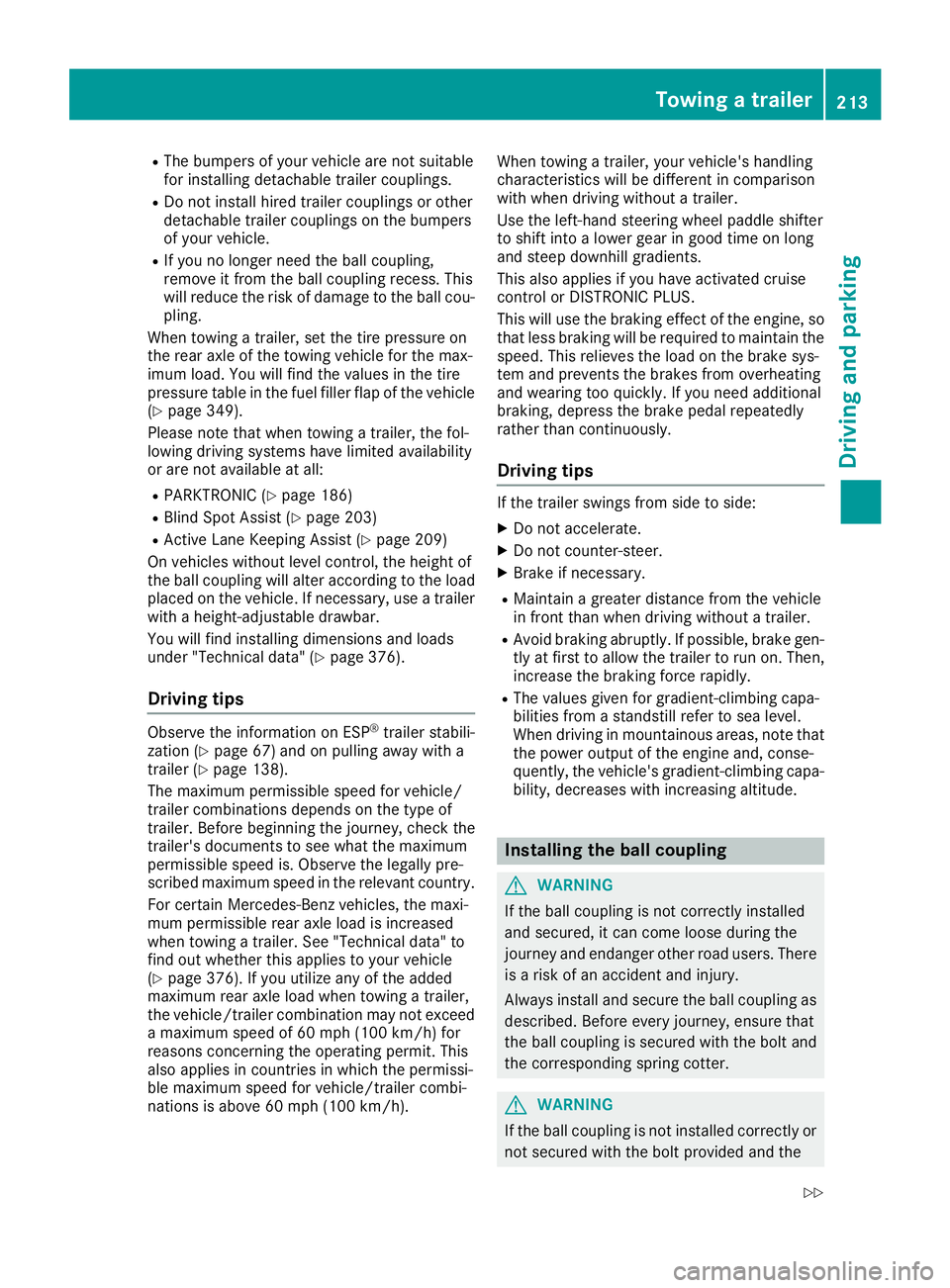
Installing the ball coupling
GWARNING
If the ball coupling is not correctly installed
and secured, it can come loose during the
journey and endanger other road users. There is a risk of an accident and injury.
Always install and secure the ball coupling as
described. Before every journey, ensure that
the ball coupling is secured with the bolt and
the corresponding spring cotter.
GWARNING
If the ball coupling is not installed correctly or not secured with the bolt provided and the
Towing a trailer213
Driving and parking
Z
Page 217 of 382
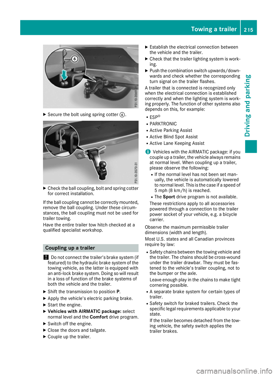
XSecure the bolt using spring cotterB.
XCheck the ball coupling, bolt and spring cotter
for correct installation.
If the ball coupling cannot be correctly mounted,
remove the ball coupling. Under these circum-
stances, the ball coupling must not be used for
trailer towing.
Have the entire trailer tow hitch checked at a
qualified specialist workshop.
Coupling up a trailer
!
Do not connect the trailer's brake system (if
featured) to the hydraulic brake system of the
towing vehicle, as the latter is equipped with
an anti-lock brake system. Doing so will result
in a loss of function of the brake systems of
both the vehicle and the trailer.
XShift the transmission to position P.
XApply the vehicle's electric parking brake.
XStart the engine.
XVehicles with AIRMATIC package: select
normal level and the Comfortdrive program.
XSwitch off the engine.
XClose the doors and tailgate.
XCouple up the trailer.
XEstablish the electrical connection between
the vehicle and the trailer.
XCheck that the trailer lighting system is work-
ing.
XPush the combination switch upwards/down-
wards and check whether the corresponding
turn signal on the trailer flashes.
A trailer that is connected is recognized only
when the electrical connection is established
correctly and when the lighting system is work-
ing properly. The function of other systems also
depends on this, for example:
RESP®
RPARKTRONIC
RActive Parking Assist
RActive Blind Spot Assist
RActive Lane Keeping Assist
iVehicles with the AIRMATIC package: if you
couple up a trailer, the vehicle always remains
at normal level. When coupling up a trailer,
please observe the following:
RIf the normal level has not been set man-
ually, the vehicle is automatically lowered
to normal level. This is the case if a speed of
5 mph (8 km/h) is reached.
RThe Sport drive program is not available.
These restrictions apply to all accessories
powered through a connection to the trailer
power socket of your vehicle, e.g. a bicycle
carrier.
Observe the maximum permissible trailer
dimensions (width and length).
Most U.S. states and all Canadian provinces
require by law:
RSafety chains between the towing vehicle and
the trailer. The chains should be cross-wound
under the trailer drawbar. They must be fas-
tened to the vehicle's trailer coupling, not to
the bumper or the axle.
Leave enough play in the chains to make tight
cornering possible.
RA separate brake system for certain types of
trailer.
RSafety switch for braked trailers. Check the
specific legal requirements applicable to your
state.
If the trailer becomes detached from the tow-
ing vehicle, the safety switch applies the
trailer brakes.
Towing a trailer215
Driving and parking
Z
Page 218 of 382
Towing a trailer
There are numerous legal requirements con-
cerning the towing of a trailer, e.g. speed restric-tions. Make sure that your car/trailer combina-
tion complies with the local regulations:
Rin your place of residence
Rin the location to which you are driving
The police and local authorities can provide reli- able information.
Observe the following when towing a trailer:
RTo gain driving experience and to become
accustomed to the new handling characteris-
tics, you should practice the following in a
traffic-free location:
-cornering
-stopping
-backing up
RBefore driving, check:
-trailer tow hitch
-safety switch for braked trailers
-safety chains
-electrical connections
-lights
-wheels
RAdjust the exterior mirrors to provide an
unobstructed view of the rear section of the
trailer.
RIf the trailer has electronically controlled
brakes, pull away carefully. Brake manually
using the brake controller and check whether
the brakes function correctly.
RSecure any objects on the trailer to prevent
the cargo from slipping when the vehicle is in
motion.
RWhen you couple up a trailer, check at regular
intervals that the load is firmly secured. If the
tra
iler is equipped with trailer lights and
brakes, check the trailer to ensure that these
are working.
RBear in mind that the handling will be less
stable when towing a trailer than when driving
without one. Avoid sudden steering move-
ments.
RThe vehicle/trailer combination is heavier,
accelerates more slowly, has a decreased
gradient climbing capability and a longer
braking distance.
It is more susceptible to side winds and
requires more careful steering.
RIf possible, do not brake suddenly, but instead depress the brake pedal moderately at first so
that the trailer can activate its brakes. Then
increase the pressure on the brake pedal.
RIf the automatic transmission repeatedly
shifts between gears on uphill or downhill gra-
dients, shift to a lower gear using the left-hand
steering wheel paddle shifter.
A lower gear and lower speed reduce the risk
of engine failure.
RWhen driving downhill, shift to a lower gear toutilize the engine's braking effect.
Avoid continuous brake application as this
may overheat the vehicle brakes and, if instal-
led, the trailer brakes.
RIf the coolant temperature increases dramat-
ically while the air-conditioning system is
switched on, switch off the air-conditioning
system.
Coolant heat can also be dissipated by open-
ing the windows and switching the ventilation blower and the interior temperature to the
highest level.
RWhen overtaking, pay particular attention to
the extended length of your vehicle/trailer
combination.
Due to the length of the vehicle/trailer com-
bination, you require additional road space in
relation to the vehicle you are overtaking
before you can change back to the original
lane.
Decoupling a trailer
GWARNING
If you uncouple a trailer with the overrun
brake engaged, you could trap your hand
between the vehicle and the trailer drawbar.
There is a risk of injury.
Do not uncouple a trailer if the overrun brake
is engaged.
GWARNING
Vehicles with level control:
The vehicle is lowered as soon as you discon-
nect the trailer cable. This could result in your
limbs or those of other people that are
between the vehicle body and tires or under-
216Towing a trailer
Driving an d parking
Page 219 of 382

neath the vehicle being trapped. There is a
risk of injury.
Make sure that nobody is in the immediate
vicinity of the wheel housings or under the
vehicle when you disconnect the trailer cable.
!Do not disconnect a trailer with an engaged
overrun brake. Otherwise, your vehicle could
be damaged by the rebounding of the overrun brake.
XShift the transmission to position P.
XApply the vehicle's electric parking brake.
XStart the engine.
XClose the doors and tailgate.
XApply the trailer's parking brake.
XDetach the trailer cable and decouple the
trailer.
XSwitch off the engine.
Permissible trailer loads and drawbar
loads
Weight specifications
Maximum allowable gross mass
The gross vehicle weight of the trailer is calcu-
lated by adding the weight of the trailer to the
weight of the load and equipment on the trailer. You will find installing dimensions and loads
under "Technical data" (
Ypage 376).
Permissible noseweight
You will find installing dimensions and loads
under "Technical data" (Ypage 376).
Loading a trailer
RWhen loading the trailer, make sure that nei-
ther the permissible gross weight of the trailer
nor the gross vehicle weight are exceeded.
The permissible gross vehicle weight is indi-
cated on the identification plate located on
the B-pillar on the driver's side of the vehicle.
You can find the maximum permissible values
on the type plates of your vehicle and the
trailer. When calculating how much weight the vehicle and trailer may carry, pay atten-
tion to the respective lowest values.
RThe trailer drawbar load on the ball coupling
must be added to the rear axle load to avoid
exceeding the permissible gross axle weight.
The permissible gross vehicle weight is indi-
cated on the identification plate located on
the B-pillar on the driver's side of the vehicle.
iMercedes-Benz recommends a trailer load
where the trailer drawbar noseweight
accounts for 8 % to 15 % of the trailer's per-
missible gross weight.
iThe weight of additional accessories, pas-
sengers, and cargo reduces the permissible
trailer load and drawbar load for your vehicle.
Checking the vehicle and trailer weight
RTo check that the weights of the towing vehi-
cle and the trailer comply with the maximum
permissible values, have the vehicle/trailer
combination (including the driver, passen-
gers, and cargo with a fully laden trailer)
weighed on a calibrated weighbridge.
RCheck the gross axle weight rating of the front and rear axles, the gross weight of the trailer
and the trailer drawbar noseweight.
Removing the ball coupling
XRemove the spring cotter.
XRemove the bolt from the ball coupling
recess.
XRemove the ball coupling from the ball cou-
pling recess.
XClean the ball coupling if it is dirty.
XStow the ball coupling so that it cannot be
thrown around.
Observe the loading guidelines (
Ypage 278)
and the safety notes regarding stowage spaces
(
Ypage 279).
Information on cleaning and care of the trailer
tow hitch (
Ypage 312).
Trailer power supply
!
Accessories with a maximum power con-
sumption of 180 W can be connected to the
permanent power supply.
Towing a trailer217
Driving an d parking
Z
Page 221 of 382

Useful information
i
This Operator's Manual describes all models
and all standard and optional equipment of
your vehicle available at the time of publica-
tion of the Operator's Manual. Country-spe-
cific differences are possible. Please note
that your vehicle may not be equipped with all
features described. This also applies to
safety-related systems and functions.
iRead the information on qualified specialist
workshops (Ypage 26).
Important safety notes
GWARNING
If you operate information systems and com-
munication equipment integrated in the vehi-
cle while driving, you will be distracted from
traffic conditions. You could also lose control
of the vehicle. There is a risk of an accident.
Only operate the equipment when the traffic
situation permits. If you are not sure that this
is possible, park the vehicle paying attention
to traffic conditions and operate the equip-
ment when the vehicle is stationary.
You must observe the legal requirements for the
country in which you are currently driving when
operating the on-board computer.
GWARNING
If the instrument cluster has failed or mal-
functioned, you may not recognize function
restrictions in systems relevant to safety. The
operating safety of your vehicle may be
impaired. There is a risk of an accident.
Drive on carefully. Have the vehicle checked
at a qualified specialist workshop immedi-
ately.
If the operating safety of your vehicle is
impaired, pull over as soon as it is safe to do so.
Contact a qualified specialist workshop.
The on-board computer only shows messages or
warnings from certain systems in the multifunc-
tion display. You should therefore make sure
your vehicle is operating safely at all times. For an overview, see the instrument panel illus-
tration (
Ypage 31).
Displays and operation
Instrument cluster lighting
The lighting in the instrument cluster, in the dis-
plays and the controls in the vehicle interior can
be adjusted using the brightness control knob.
The brightness control knob is located on the
bottom left of the instrument cluster
(
Ypage 31).
XTurn the brightness control knob clockwise or
counter-clockwise.
If you turn the light switch to Ã,Tor
L, the brightness is dependent upon the
brightness of the ambient light.
iThe light sensor in the instrument cluster
automatically controls the brightness of the
multifunction display.
In daylight, the displays in the instrument
cluster are not illuminated.
Speedometer with segments
The speedometer is divided into segments only
on vehicles with DISTRONIC PLUS.
The segments in the speedometer indicate
which speed range is available.
RDISTRONIC PLUS activated (Ypage 170):
One or two segments in the set speed range
light up.
RDISTRONIC PLUS detects a vehicle in front
that is driving at a slower speed than the
stored speed:
The segments between the speed of the vehi- cle in front and the stored speed light up.
Tachometer
!
Do not drive in the overrevving range, as this
could damage the engine.
The red band in the tachometer indicates the
engine's overrevving range.
The fuel supply is interrupted to protect the
engine when the red band is reached.
Displays and operation219
On-board computer and displays
Z
Page 222 of 382
Outside temperature display
You should pay special attention to road condi-
tions when temperatures are around freezing
point.
Bear in mind that the outside temperature dis-
play indicates the temperature measured and
does not record the road temperature.
The outside temperature display is in the multi-function display (
Ypage 221).
There is a short delay before a change in outside
temperature appears in the multifunction dis-
play.
Coolant temperature display
GWARNING
Opening the hood when the engine is over-
heated or when there is a fire in the engine
compartment could expose you to hot gases
or other service products. There is a risk of
injury.
Let an overheated engine cool down before
opening the hood. If there is a fire in the
engine compartment, keep the hood closed
and contact the fire department.
!A display message is shown if the coolant
temperature is too high.
If the coolant temperature is over 248 ‡
(120 †), do not continue driving. The engine
will otherwise be damaged.
The coolant temperature gage is in the instru-
ment cluster on the right-hand side (
Ypage 31).
Under normal operating conditions and with the
specified coolant level, the coolant temperature
may rise to 248 ‡ (120 †).
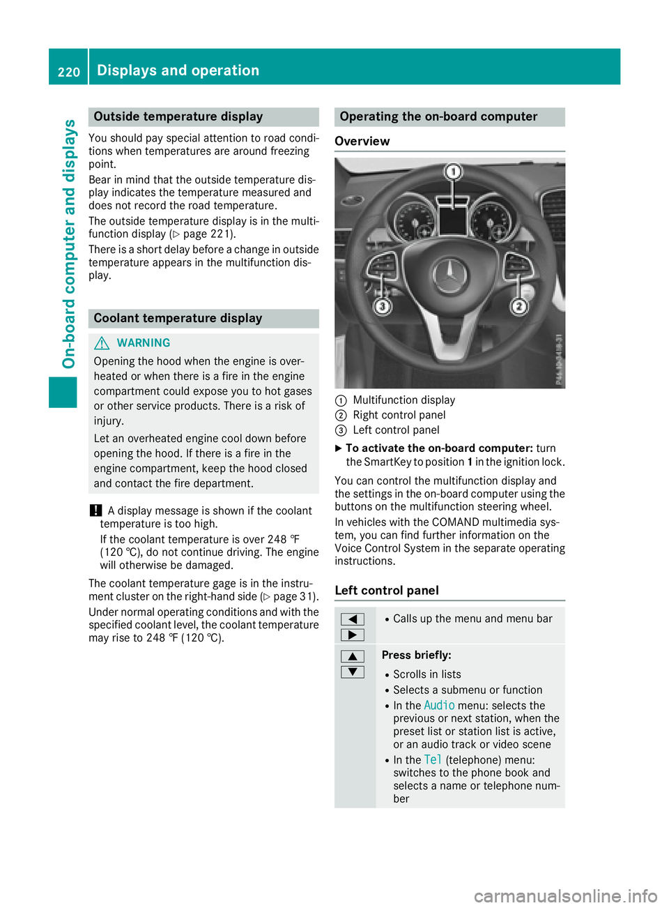
Operating the on-board computer
Overview
:Multifunction display
;Right control panel
=Left control panel
XTo activate the on-board computer: turn
the SmartKey to position 1in the ignition lock.
You can control the multifunction display and
the settings in the on-board computer using the
buttons on the multifunction steering wheel.
In vehicles with the COMAND multimedia sys-
tem, you can find further information on the
Voice Control System in the separate operating
instructions.
Left control panel
=
;RCalls up the menu and menu bar
9
:Press briefly:
RScrolls in lists
RSelects a submenu or function
RIn the Audiomenu: selects the
previous or next station, when the
preset list or station list is active,
or an audio track or video scene
RIn the Tel(telephone) menu:
switches to the phone book and
selects a name or telephone num-
ber
220Displays and operation
On-board computer and displays
Page 233 of 382

For further information on belt adjustment, see
(Ypage 42).
Switching the fold-in mirrors when lock-
ing feature on/off
This function is only available when the vehicle is
equipped with the electrical fold-in function.
When you activate theAuto.
MirrorFoldingfunction, the exterior mirrors are folded in when
the vehicle is locked. The exterior mirrors fold
out automatically again as soon as you unlock
the vehicle.
XPress the =or; button on the steering
wheel to select the Sett.menu.
XPress the:or9 button to select the
Conveniencesubmenu.
XPress ato confirm.
XPress the :or9 button to select the
Auto. Mirror Foldingfunction.
If the Auto. Mirror Foldingfunction is
switched on, the multifunction display shows
the exterior mirror in orange.
XPress the abutton to save the setting.
If you have switched the Auto. Mirror Fold‐ingon and you fold the exterior mirrors in using
button :, they will not fold out automatically
(
Ypage 105).
You can then only fold out the exterior mirrors
using button :.
Restoring the factory settings
XPress the=or; button on the steering
wheel to select the Sett.menu.
XPress the:or9 button to select the
Factory Settingsubmenu.
XPress ato confirm.
The Reset All Settings?message
appears.
XPress the :or9 button to select Noor
Yes.
XPress ato confirm the selection.
If you select Yes, the multifunction display
shows a confirmation message.
If you want to reset the Daytime Running
Lightsfunction in theLightsubmenu, you
must turn the SmartKey to position 1in the igni-
tion lock.
AMG menu (Mercedes-AMG vehicles)
WARMUP
:Digital speedometer
;Gear indicator
=Upshift indicator
?Engine oil temperature
ACoolant temperature
BTransmission fluid temperature
XPress the =or; button on the steering
wheel to select the AMGmenu.
Upshift indicator: upshift indicatorUp=
indicates that the engine has reached the
overrevving range when in the manual drive
program.
Engine/transmission oil temperature:
when the engine and transmission are at nor-
mal operating temperature, oil tempera-
ture ?and Bare displayed in white in the
multifunction display.
If the multifunction display shows oil temper-
ature ?orB in blue, the engine or the
transmission are not yet at normal operating
temperature. Avoid driving at full engine out-
put during this time.
Menus and submenus231
On-board computer and displays
Z
Page 234 of 382
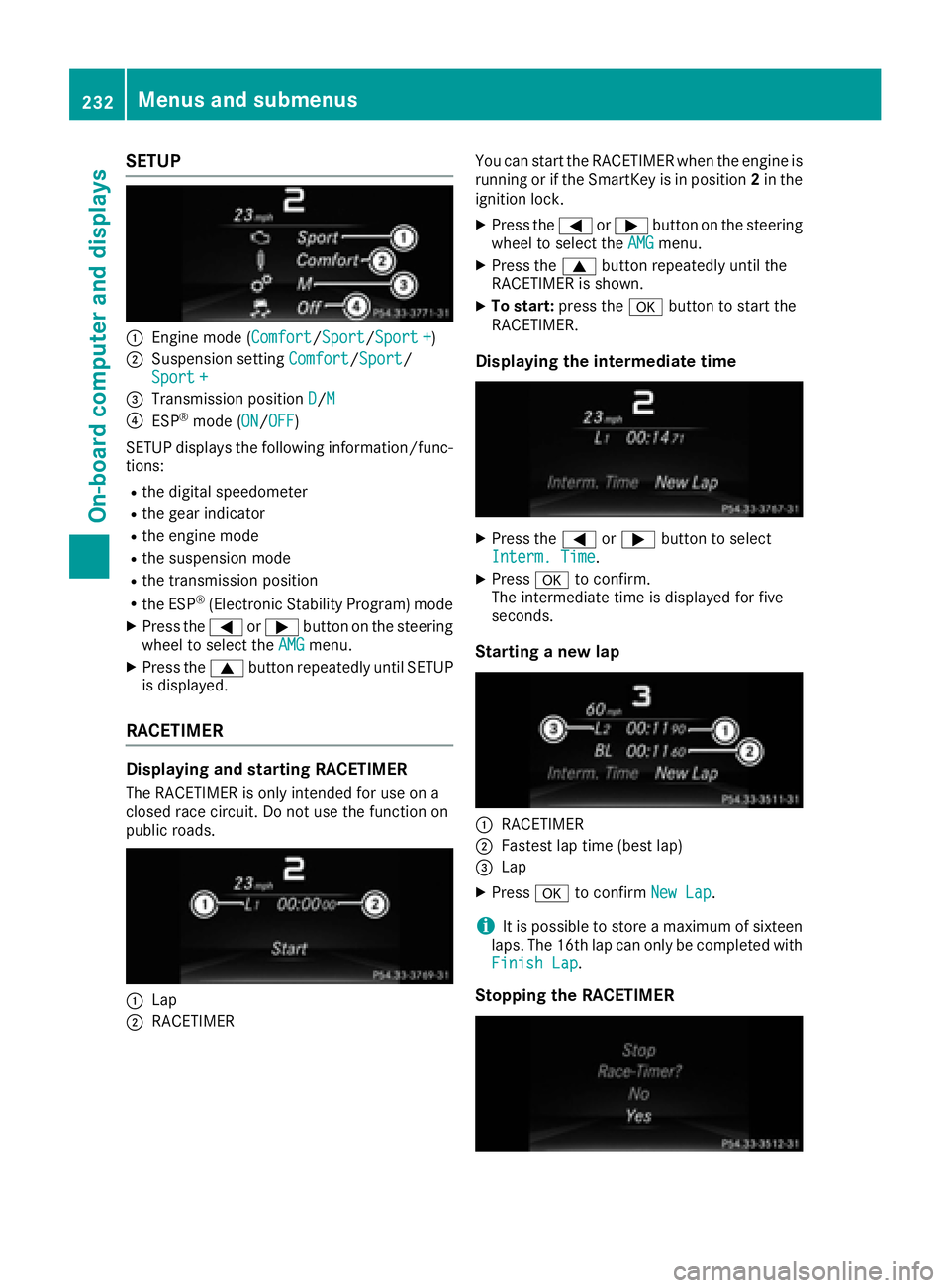
SETUP
:Engine mode (Comfort/Sport/Sport +)
;Suspension settingComfort/Sport/
Sport +
=Transmission position D/M
?ESP®mode (ON/OFF)
SETUP displays the following information/func- tions:
Rthe digital speedometer
Rthe gear indicator
Rthe engine mode
Rthe suspension mode
Rthe transmission position
Rthe ESP®(Electronic Stability Program) mode
XPress the =or; button on the steering
wheel to select the AMGmenu.
XPress the9button repeatedly until SETUP
is displayed.
RACETIMER
Displaying and starting RACETIMER
The RACETIMER is only intended for use on a
closed race circuit. Do not use the function on
public roads.
:Lap
;RACETIMER You can start the RACETIMER when the engine is
running or if the SmartKey is in position
2in the
ignition lock.
XPress the =or; button on the steering
wheel to select the AMGmenu.
XPress the9button repeatedly until the
RACETIMER is shown.
XTo start: press the abutton to start the
RACETIMER.
Displaying the intermediate time
XPress the =or; button to select
Interm. Time.
XPress ato confirm.
The intermediate time is displayed for five
seconds.
Starting a new lap
:RACETIMER
;Fastest lap time (best lap)
=Lap
XPress ato confirm New Lap.
iIt is possible to store a maximum of sixteen
laps. The 16th lap can only be completed with
Finish Lap
.
Stopping the RACETIMER
232Menus and submenus
On-board computer and displays