2016 MERCEDES-BENZ GLC-Class tailgate
[x] Cancel search: tailgatePage 137 of 418

Switching the rear window wiper on/
off
Combination switch
:
èSwitch
2/5bWipes with washer fluid
3ISwitches on intermittent wiping
40 Switches off intermittent wiping
XTurn the SmartKey to position 1or 2in the
ignition lock (
Ypage 153).
XTurn switch :on the combination switch
to the corresponding position.
When the rear window wiper is switched on,
the icon appears in the instrument cluster.
Replacing the wiper blades
Important safety notes
GWARNING
If the windshield wipers begin to move while
you are changing the wiper blades, you could be trapped by the wiper arm. There is a risk of
injury.
Always switch off the windshield wipers and
ignition before changing the wiper blades.
!Never open the hood/tailgate if a wiper
arm has been folded away from the wind-
shield/rear window.
Never fold a windshield wiper arm without a
wiper blade back onto the windshield/rear
window.
Hold the windshield wiper arm firmly when
you change the wiper blade. If you release the wiper arm without a wiper blade and it
falls onto the windshield/rear window, the
windshield/rear window may be damaged
by the force of the impact.
Mercedes-Benz recommends that you have
the wiper blades changed at a qualified
specialist workshop.
!To avoid damaging the wiper blades,
make sure that you touch only the wiper
arm of the wiper.
Changing the windshield wiper blades
Adjusting the wiper blades so that they
are vertical
On vehicles without KEYLESS-GO:
XTurn the SmartKey to position 1or 2in the
ignition lock (
Ypage 153).
XSet the windshield wiper to position °.
XWhen the wiper arms have reached the ver-
tical position, turn the SmartKey to position
0 and remove it from the ignition lock.
XFold the wiper arm away from the wind-
shield.
On vehicles with KEYLESS-GO:
XSwitch off the engine.
XRemove your foot from the brake pedal.
XSet the windshield wiper to the °posi-
tion.
XPress the Start/Stop button repeatedly
until the windshield wiper starts.
XWhen the wiper arms have reached the ver- tical position, press the Start/Stop button.
XFold the wiper arm away from the wind-
shield.
Windshield wipers135
Lights and windshield wipers
Z
Page 234 of 418

cleaned, remove the ball coupling. The trailer
tow hitch must then not be used to tow a
trailer, as safe operation cannot be guaran-
teed.
Have the entire trailer tow hitch checked at a
qualified specialist workshop.
Coupling up a trailer
!
Do not connect the trailer's brake system
(if featured) to the hydraulic brake system
of the towing vehicle, as the latter is equip-
ped with an anti-lock brake system. Doing
so will result in a loss of function of the
brake systems of both the vehicle and the
trailer.
XShift the transmission to position P.
XApply the vehicle's electric parking brake.
XStart the engine.
XVehicles with AIR BODY CONTROL:
selectComfort driving program or Trailer
off-road program.
XSwitch off the engine.
XClose the doors and tailgate.
XCouple up the trailer.
XEstablish the electrical connection
between the vehicle and the trailer.
XCheck that the trailer lighting system is
working.
XPush the combination switch upwards/
downwards and check whether the corre-
sponding turn signal on the trailer flashes.
A trailer that is connected is recognized only
when the electrical connection is established
correctly and when the lighting system is
working properly. The function of other sys-
tems also depends on this, for example:
RESP®
RPARKTRONIC
RActive Parking Assist
RActive Blind Spot Assist
RActive Lane Keeping Assist
iVehicles with AIR BODY CONTROL: if you
couple up a trailer, the vehicle always
remains at highway level. When coupling up
a trailer, please observe the following:
RUnless highway level has been set man-
ually, the vehicle is automatically low-
ered to highway level. This is the case if a
speed of 5 mph (8 km/h) is reached.
These restrictions apply to all accessories
powered through a connection to the trailer
power socket of your vehicle, e.g. a bicycle
carrier.
Observe the maximum permissible trailer
dimensions (width and length).
Most U.S. states and all Canadian provinces
require by law:
RSafety chains between the towing vehicle
and the trailer. The chains should be cross-
wound under the trailer drawbar. They must
be fastened to the vehicle's trailer cou-
pling, not to the bumper or the axle.
Leave enough play in the chains to make
tight cornering possible.
RA separate brake system for certain types
of trailer.
RSafety switch for braked trailers. Check the specific legal requirements applicable to
your state.
If the trailer becomes detached from the
towing vehicle, the safety switch applies
the trailer brakes.
Towing a trailer
There are numerous legal requirements con-
cerning the towing of a trailer, e.g. speed
restrictions. Make sure that your car/trailer
combination complies with the local regula-
tions:
Rin your place of residence
Rin the location to which you are driving
The police and local authorities can provide
reliable information.
232Towing a trailer
Driving and parking
Page 236 of 418

XMake sure that the automatic transmissionis set to position P.
XApply the vehicle's parking brake.
XClose all doors and the tailgate.
XApply the trailer's parking brake.
XRemove the trailer cable and decouple the
trailer.
Removing the ball coupling
XRemove the spring cotter.
XRemove the bolt from the ball coupling
recess.
XRemove the ball coupling from the ball cou-
pling recess.
XClean the ball coupling if it is dirty.
XStow the ball coupling so that it cannot be
thrown around.
Observe the loading guidelines (
Ypage 306)
and the safety notes regarding stowage
spaces (
Ypage 306).
Information on cleaning and care of the trailer
tow hitch (
Ypage 349).
Trailer power supply
The trailer socket of your vehicle is equipped
at the factory with a permanent power supply.
The permanent power supply is supplied via
trailer socket pin 4.
!Accessories with a maximum power con-
sumption of 180 W can be connected to the
permanent power supply.
You must not charge a trailer battery using
the power supply.
The trailer's permanent power supply is
switched off in the event of low vehicle supply
voltage and after six hours at the latest.
A qualified specialist workshop can provide
more information about installing the trailer
electrics.
Permissible trailer loads and trailer
drawbar noseweights
Weight specifications
The gross trailer weight is calculated by add-
ing the weight of the trailer to the weight of
the load and equipment on the trailer.
You will find installing dimensions and loads
under "Technical data" (
Ypage 415).
Loading a trailer
RWhen loading the trailer, make sure that
neither the permissible gross weight of the
trailer nor the gross vehicle weight is
exceeded. The permissible gross vehicle
weight is indicated on the identification
plate on the B-pillar on the driver's side of
the vehicle.
You can find the maximum permissible val-
ues on the type plates of your vehicle and
the trailer. When calculating how much
weight the vehicle and trailer may carry,
pay attention to the respective lowest val-
ues.
RThe trailer drawbar load on the ball coupling
must be added to the rear axle load to avoid
exceeding the permissible gross axle
weight. The permissible gross vehicle
weight is indicated on the identification
plate on the B-pillar on the driver's side of
the vehicle.
iMercedes-Benz recommends a trailer
load where the trailer drawbar noseweight
accounts for 8% to 15% of the trailer's per-
missible gross weight.
iThe weight of other accessories, passen-
gers and loads reduces:
Rthe permissible trailer load
Rthe permissible noseweight that your
vehicle can tow
234Towing a trailer
Driving and parking
Page 290 of 418

Display messagesPossible causes/consequences andMSolutions
Reversing Not Pos‐
sible Service
Required
You cannotshift into th etransmissio nposition Rdue to amal-
function .
The transmissio nposition sP, Nor Dcontinue to be available.
A warnin gtone also sounds.
XVisit aqualified specialist workshop .
Transmission Mal‐
function Stop
Amalfunction has occurred in th emechanica ltransmissio ncom-
ponents .
A warnin gtone also sounds. The gearbox automatically shift sto
position N.
XPull ove rand stop th evehicl esafely as soo nas possible, payin g
attention to roa dand traffic conditions.
XShift th etransmissio nto position P.
XSecureth evehicl eagainst rollin gaway (Ypage 172).
XNotify aqualified specialist workshop or breakdown service.
Sto pVehicl eLeave
Engine Runnin g
WaitTransmission
Coolin g
The transmissio nhas overheated. Pullin gaway can be temporarily
impaire dor no tpossible.
XPull ove rand stop th evehicl esafely as soo nas possible, payin g
attention to roa dand traffic conditions. Do no tcontinue drivin g
under any circumstances.
XWait until th edisplay message disappear sbefore pullin gaway.
AThe tailgat eis open .
GWARNIN G
Whenth eengin eis running ,exhaus tgase scan ente rth evehicl e
interio rif th etailgat eis open .
There is aris kof poisoning.
XClos eth etailgate.
?The hoo dis open . Awarnin gtone also sounds.
GWARNIN G
The open hoo dmay bloc kyour vie wwhen th evehicl eis in motion .
There is aris kof an accident.
XPull ove rand stop th evehicl esafely as soo nas possible, payin g
attention to roa dand traffic conditions.
XSecur eth evehicl eagainst rollin gaway (Ypage 172).
XCloseth ehood.
288Display messages
On-board computer and displays
Page 308 of 418

Useful information
i
This Operator's Manual describes all
models and all standard and optional equip-
ment of your vehicle available at the time of
publication of the Operator's Manual.
Country-specific differences are possible.
Please note that your vehicle may not be
equipped with all features described. This
also applies to safety-related systems and
functions.
iRead the information on qualified special-
ist workshops (
Ypage 27).
Stowage areas
Loading guidelines
GWARNING
Combustion engines emit poisonous exhaust
gases such as carbon monoxide. If the tailgate
is open when the engine is running, particu-
larly if the vehicle is moving, exhaust fumes
could enter the passenger compartment.
There is a risk of poisoning.
Turn off the engine before opening the tail-
gate. Never drive with the tailgate open.
GWARNING
If objects, luggage or loads are not secured or
not secured sufficiently, they could slip, tip
over or be flung around and thereby hit vehicle
occupants. There is a risk of injury, particu-
larly in the event of sudden braking or a sud-
den change in direction.
Always store objects so that they cannot be
flung around. Secure objects, luggage or
loads against slipping or tipping before the
journey.
GWARNING
The exhaust tail pipe and tail pipe trim can
become very hot. If you come into contact
with these parts of the vehicle, you could burn
yourself. There is a risk of injury.
Always be particularly careful around the
exhaust tail pipe and the tail pipe trim. Allow
these components to cool down before touch-
ing them.
The handling characteristics of a laden vehi-
cle are dependent on the distribution of the
load within the vehicle. For this reason, you
should observe the following notes when
transporting a load:
RNever exceed the maximum permissible
gross vehicle mass or the gross axle weight
rating for the vehicle (including occupants).
The values are specified on the vehicle
identification plate on the B-pillar of the
driver's door.
RThe cargo compartment is the preferred
place to carry objects.
RPosition heavy loads as far forwards as pos-
sible and as low down in the cargo com-
partment as possible.
RThe load must not protrude above the
upper edge of the seat backrests.
RAlways place the load behind unoccupied
seats if possible.
RHook in the cargo net when loading.
RSecure the load with sufficiently strong and
wear-resistant tie-downs. Pad sharp edges
for protection.
Stowage spaces
Important safety notes
GWARNING
If objects in the passenger compartment are
stowed incorrectly, they can slide or be
thrown around and hit vehicle occupants.
There is a risk of injury, particularly in the
event of sudden braking or a sudden change
in direction.
306Stowage areas
Stowage and features
Page 312 of 418

otherwise be damaged or could themselves
damage the rear seats.
Observe the loading guidelines (
Ypage 306).
The outside and the middle rear seat backr-
ests can be folded down separately to
increase the cargo compartment capacity.
The division ratio is 40% to 20% to 40%.
Both outside seat backrests in the rear com-
partment are electrically unlocked with the
release handles either in the cargo compart-
ment or beside the seat backrests in the rear
compartment (vehicles with EASY-PACK tail-
gate only). The corresponding rear seat
backrests then fold forward automatically.
Folding the rear seat backrests forward
XVehicles without memory function: if nec-
essary, move the driver's or front-
passenger seat forward.
XVehicles with memory function: when one
or both parts of the rear seat backrest are
folded forward, the respective front seat
moves forward slightly, when necessary, in
order to avoid contact.
XFully insert the rear seat backrest head
restraints.
XHook in seat belt buckle tongue :through
seat belt retainer ;.
Release handle in the cargo compartment
Release handle next to the seat backrest (vehicles
with EASY-PACK tailgate only)
Left and right seat backrest:
XPull the left-hand or right-hand release han-
dle at the rear in cargo compartment :or
at the side beside backrests :.
The corresponding backrest folds for-
wards.
XMove the driver's or front-passenger seat
back if necessary.
310Stowage areas
Stowage and features
Page 317 of 418

The cargo net is located in the stowage space
under the cargo compartment floor.
XOpen both Velcro fasteners and remove the
cargo net.
XUnroll and unfold the cargo net.
The upper and lower guide rods must
engage audibly.
Attaching and tightening the cargo net
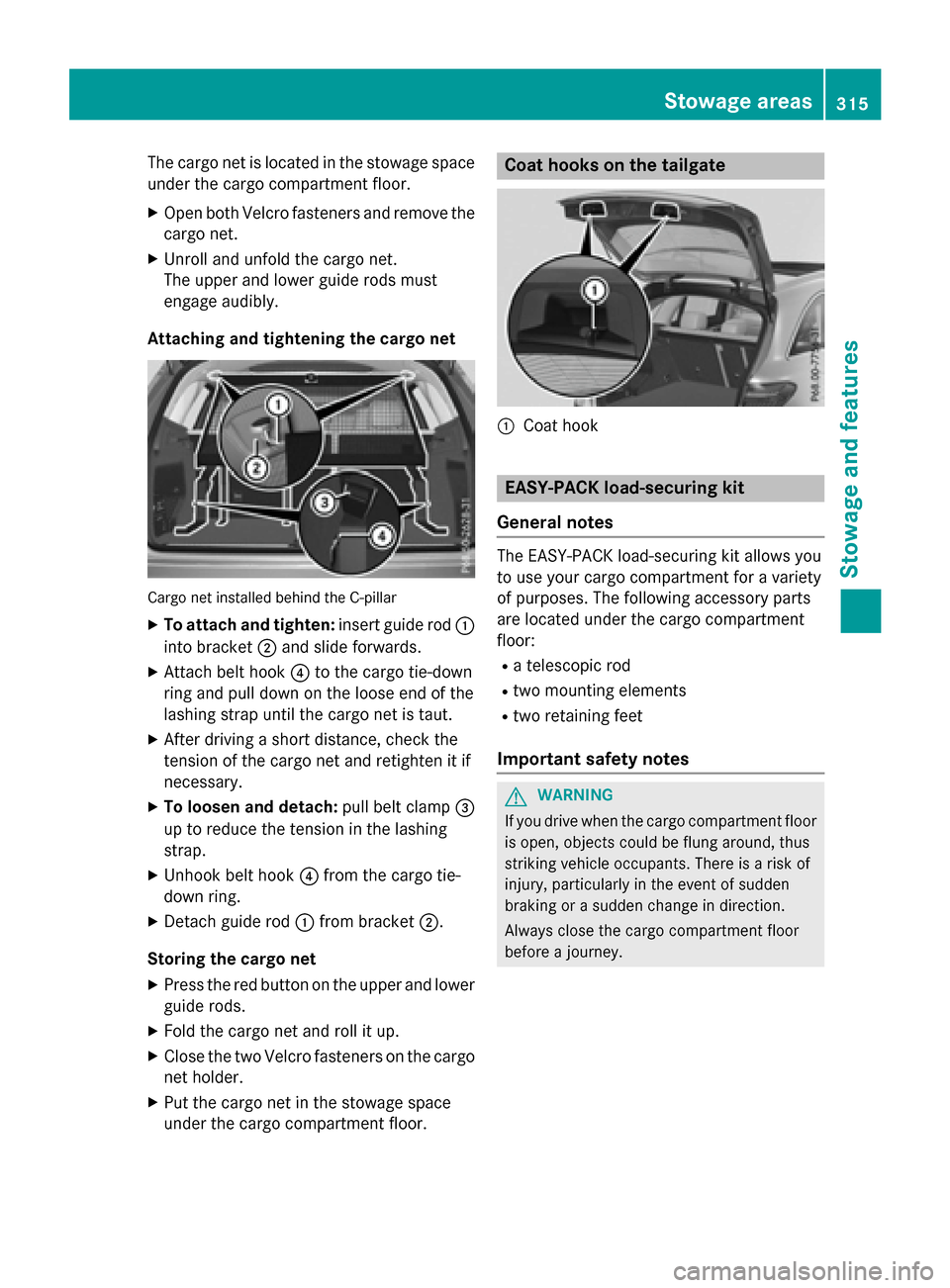
Cargo net installed behind the C-pillar
XTo attach and tighten: insert guide rod:
into bracket ;and slide forwards.
XAttach belt hook ?to the cargo tie-down
ring and pull down on the loose end of the
lashing strap until the cargo net is taut.
XAfter driving a short distance, check the
tension of the cargo net and retighten it if
necessary.
XTo loosen and detach: pull belt clamp=
up to reduce the tension in the lashing
strap.
XUnhook belt hook ?from the cargo tie-
down ring.
XDetach guide rod :from bracket ;.
Storing the cargo net
XPress the red button on the upper and lower
guide rods.
XFold the cargo net and roll it up.
XClose the two Velcro fasteners on the cargo
net holder.
XPut the cargo net in the stowage space
under the cargo compartment floor.
Coat hooks on the tailgate
:Coat hook
EASY-PACK load-securing kit
General notes
The EASY-PACK load-securing kit allows you
to use your cargo compartment for a variety
of purposes. The following accessory parts
are located under the cargo compartment
floor:
Ra telescopic rod
Rtwo mounting elements
Rtwo retaining feet
Important safety notes
GWARNING
If you drive when the cargo compartment floor is open, objects could be flung around, thus
striking vehicle occupants. There is a risk of
injury, particularly in the event of sudden
braking or a sudden change in direction.
Always close the cargo compartment floor
before a journey.
Stowage areas315
Stowage and features
Z
Page 318 of 418

Installation
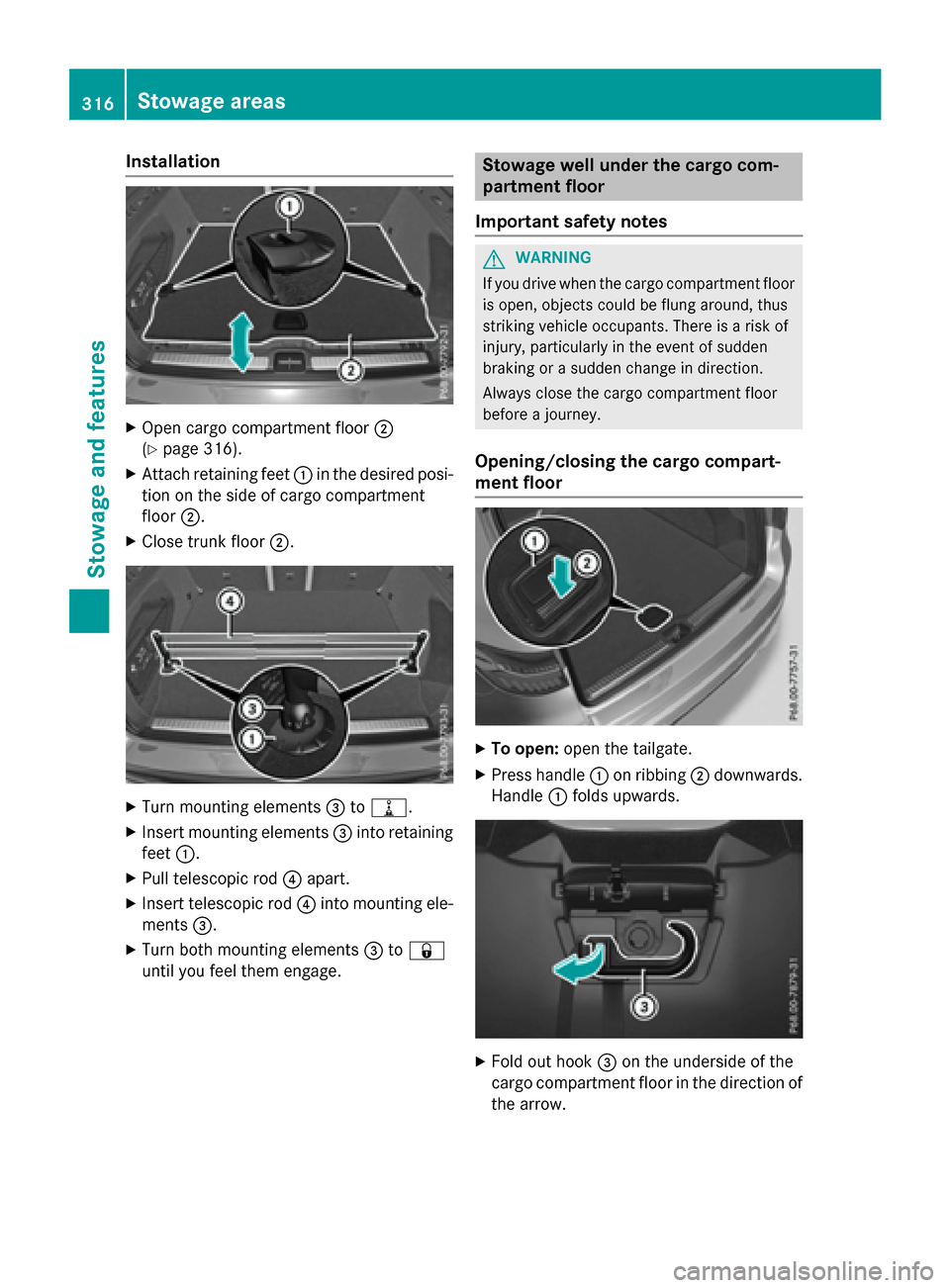
XOpen cargo compartment floor;
(
Ypage 316).
XAttach retaining feet :in the desired posi-
tion on the sideof cargo compartment
floor ;.
XClose trunk floor ;.
XTurn mounting elements =to=.
XInsert mounting elements =into retaining
feet :.
XPull telescopic rod?apart.
XInsert telescopic rod ?into mounting ele-
ments =.
XTurn both mounting elements =to&
unt ilyou feel them engage.
Stowage well under the cargo com-
partment floor
Important safety notes
GWARNIN G
If you driv ewhen th ecargo compartmen tfloor
is open ,objects could be flun garound, thus
striking vehicl eoccupants. Ther eis aris kof
injury, particularly in th eevent of sudde n
braking or asudde nchang ein direction .
Always close th ecargo compartmen tfloor
before ajourney.
Opening/closing the cargo compart-
ment floor
XTo open: open the tailgate.
XPress handle :on ribbing ;down wards.
Han dle:folds upwards.
XFoldout hook =on the underside of the
cargo compartment floor inthe dire ction of
the arrow.
316Stowage areas
Stowage and features