2016 MERCEDES-BENZ GLC-Class fuel cap
[x] Cancel search: fuel capPage 231 of 418

speed and do not countersteer. Apply the
brake as necessary.
Please observe the manufacturer's operating
instructions for the trailer coupling if a
detachable trailer coupling is used.
Couple and uncouple the trailer carefully. If
you do not couple the trailer to the towing
vehicle correctly, the trailer could become
detached.
Make sure that the following values are not
exceeded:
Rthe permissible trailer drawbar noseweight
Rthe permissible trailer load
Rthe permissible rear axle load of the towing
vehicle
Rthe maximum permissible gross vehicle
weight of both the towing vehicle and the
trailer
The applicable permissible values, which
must not be exceeded, can be found:
Rin the vehicle documents
Ron the identification plates of the trailer tow hitch, the trailer and the vehicle
If the values differ, the lowest value applies.
You will find the values approved by the man-
ufacturer on the vehicle identification plates
and those for the towing vehicle under "Tech-
nical data" (
Ypage 416).
When towing a trailer, your vehicle's handling
characteristics will be different in comparison
with when driving without a trailer.
The vehicle/trailer combination:
Ris heavier
Ris restricted in its acceleration and gradi-
ent-climbing capability
Rhas an increased braking distance
Ris affected more by strong crosswinds
Rdemands more sensitive steering
Rhas a larger turning radius
This could impair the handling characteris-
tics. When towing a trailer, always adjust your
speed to the current road and weather con-
ditions. Do not exceed the maximum permis-
sible speed for your vehicle/trailer combina-
tion.
General notes
RDo not exceed the legally prescribed max-
imum speed for vehicle/trailer combina-
tions in the relevant country.
This lowers the risk of an accident.
ROnly install an approved trailer coupling on
your vehicle.
Further information on availability and on
installation is available from any authorized Mercedes-Benz Center.
RThe bumpers of your vehicle are not suita-
ble for installing detachable trailer cou-
plings.
RDo not install hired trailer couplings or
other detachable trailer couplings on the
bumpers of your vehicle.
RTo reduce the risk of damage to the ball
coupling, remove it from the ball coupling
recess when not in use.
iWhen towing a trailer, set the tire pres-
sure on the rear axle of the towing vehicle
for a maximum load; see the tire pressure
table in the fuel filler flap (
Ypage 393).
Please note that when towing a trailer,
PARKTRONIC (
Ypage 198) is only available
with limitations or not at all.
iOn vehicles without level control, the
height of the ball coupling will alter accord-
ing to the load placed on the vehicle. If nec-
essary, use a trailer with a height-adjusta-
ble drawbar.
You will find installing dimensions and loads
under "Technical data" (
Ypage 415).
Driving tips
iObserve the notes on ESP®trailer stabi-
lization (
Ypage 75).
Towing a trailer229
Driving and parking
Z
Page 280 of 418

Display messagesPossible causes/consequences andMSolutions
4
Check Engine Oil
At NextRefueling
The engin eoil level has dropped to th eminimum level.
A warnin gtone also sounds.
!Avoid lon gjourneys wit hto olittl eengin eoil. The engin ewill
otherwise be damaged.
XChec kth eoil level when next refueling, at th elatest
(
Ypage 339).
XIf necessary, add engin eoil (Ypage 340).
If th eengin eoil need stopping up more often:
XContac t aqualified specialist workshop and hav eth eengin e
checked.
Information on approve dengin eoils can be obtained from aquali-
fie dspecialist workshop or on th eInternet at http:/ /
bevo.mercedes-benz.co m.
8
Fuel Level Low
The fuel level has dropped into the reserve range.
XRefuel at the nearest gas station.
CThere is only a very small amount of fuel in the fuel tank.
XRefuel at the nearest gas station without fail.
8
Gas Cap Loose
The fuel system pressure is too low. The fuel filler cap is not closed
correctly or the fuel system is leaking.
XCheck that the fuel filler cap is correctly closed.
If the fuel filler cap is not correctly closed:
XClose the fuel filler cap.
If the fuel filler cap is correctly closed:
XVisit a qualified specialist workshop.
278Display messages
On-board computer and displays
Page 301 of 418

Engine
Warning/
indicator
lampNSignal type
Possible causes/consequences and M
Solutions
;NThe yellow Check Engine warning lamp lights up while the engine is running.
There may be a malfunction, for example:
Rin the engine management
Rin the fuel injection system
Rin the exhaust system
Rin the ignition system (for vehicles with gasoline engines)
Rin the fuel system
The emission limit values may be exceeded and the engine may be in emer-
gency mode.
XVisit a qualified specialist workshop immediately.
In some states, you must immediately visit a qualified specialist workshop as
soon as the yellow Check Engine warning lamp lights up. This is due to the legal
requirements in effect in these states. If in doubt, check whether such legal
regulations apply in the state in which you are currently driving.
8N The yellow reserve fuel warning lamp lights up while the engine is running.
The fuel level has dropped into the reserve range.
XRefuel at the nearest gas station.
8N The yellow reserve fuel warning lamp flashes while the vehicle is in motion.
In addition, the ;Check Engine warning lamp may light up.
The fuel system pressure is too low. The fuel filler cap is not closed correctly
or the fuel system is leaking.
XCheck that the fuel filler cap is correctly closed.
XIf the fuel filler cap is not correctly closed: close the fuel filler cap.
XIf the fuel filler cap is closed:visit a qualified specialist workshop.
?NThe red coolant warning lamp lights up while the engine is running and the
coolant temperature gage is at the start of the bar display.
The temperature sensor for the coolant temperature gage is defective.
The coolant temperature is no longer being monitored. There is a risk of engine
damage if the coolant temperature is too high.
XPull over and stop the vehicle safely and switch off the engine, paying
attention to road and traffic conditions. Do not continue driving under any
circumstances.
XSecure the vehicle against rolling away (Ypage 172).
XConsult a qualified specialist workshop.
Warning and indicator lamps in the instrument cluster299
On-board computer and displays
Z
Page 362 of 418

suitable for higher speeds. There is a risk of
accident.
You should therefore adapt your driving style
accordingly and drive carefully. Do not exceedthe specified maximum speed with a tire that
has been repaired using tire sealant.
The maximum permissible speed for a tire
sealed with tire sealant is 50 mph (80 km/h). The upper part of the TIREFIT sticker must be
affixed to the instrument cluster in the driv-
er's field of vision.
!After use, excess tire sealant may run out
of the filler hose. This could cause stains.
Therefore, place the tire sealant bottle with
filler hose in the plastic bag which is con-
tained in the TIREFIT kit.
HEnvironmental note
Have the used tire sealant bottle disposed of
professionally, e.g. at a qualified specialist
workshop.
If a tire pressure of 180 kPa (1.8 bar/26 psi)
has been attained after five minutes:
XSwitch off the tire inflation compressor.
XUnscrew the filler hose from the valve of
the faulty tire.
XStow the tire sealant bottle and the tire
inflation compressor.
XPull away immediately.
XStop after driving for approximately ten
minutes and check the tire pressure with
the tire inflation compressor.
The tire pressure must now be at least
130 kPa (1.3 bar/19 psi).
GWARNING
If the required tire pressure is not reached
after driving for a short period, the tire is too
badly damaged. The tire sealant cannot repair
the tire in this instance. Damaged tires and a
tire pressure that is too low can significantly
impair the vehicle's braking and driving char-
acteristics. There is a risk of accident.
Do not continue driving. Contact a qualified
specialist workshop.
iIn cases such as the one mentioned
above, contact an authorized Mercedes-
Benz Center. Or call 1-800-FOR-MERCedes (in the USA) or 1-800-387-0100 (in Can-
ada).
XCorrect the tire pressure if it is still at least
130 kPa (1.3 bar/19 psi). See the Tire andLoading Information placard on the driver's
side B-pillar or the tire pressure table in the
fuel filler flap for values.
XTo increase the tire pressure: switch on
the tire inflation compressor.
XTo reduce the tire pressure: depress
pressure release button :next to pres-
sure gauge ;.
XWhen the tire pressure is correct, unscrew
the filler hose from the valve of the sealed
tire.
XScrew the valve cap onto the tire valve of
the sealed tire.
XPull the tire sealant bottle out of the tire
inflation compressor.
The filler hose remains attached to the tire
sealant bottle.
XDrive to the nearest qualified specialist
workshop and have the tire changed there.
360Flat tire
Breakdown assistance
Page 367 of 418

Jump-starting
For the jump-starting procedure, use only the jump-starting connection point in the engine
compartment, consisting of a positive terminal and a ground point.
All vehicles except vehicles with a lithium-ion battery:
GWARNING
Battery acid is caustic. There is a risk of injury.
Avoid contact with skin, eyes or clothing. Do not inhale any battery gases. Do not lean over the
battery. Keep children away from batteries. Wash away battery acid immediately with plenty of
clean water and seek medical attention.
GWARNING
During charging and jump-starting, explosive gases can escape from the battery. There is a risk of an explosion.
Particularly avoid fire, open flames, creating sparks and smoking. Ensure there is sufficient ven-
tilation while charging and jump-starting. Do not lean over a battery.
GWARNING
During the charging process, a battery produces hydrogen gas. If a short circuit occurs or sparks
are created, the hydrogen gas can ignite. There is a risk of an explosion.
RMake sure that the positive terminal of a connected battery does not come into contact with
vehicle parts.
RNever place metal objects or tools on a battery.
RIt is important that you observe the described order of the battery terminals when connecting
and disconnecting a battery.
RWhen jump-starting, make sure that the battery poles with identical polarity are connected.
RIt is particularly important to observe the described order when connecting and disconnecting
the jumper cables.
RNever connect or disconnect the battery terminals while the engine is running.
GWARNING
A discharged battery can freeze at temperatures below freezing point. When jump-starting the
vehicle or charging the battery, gases can escape from the battery. There is a risk of an explosion. Allow the frozen battery to thaw out before charging it or jump-starting.
!Avoid repeated and lengthy starting attempts. Otherwise, the catalytic converter could be
damaged by the non-combusted fuel.
If, at low temperatures, the indicator lamps/warning lamps in the instrument cluster do not
light up, it is highly likely that the discharged battery has frozen. In this case, you may neither
charge the battery nor jump-start the vehicle. The service life of a thawed-out battery may be
shorter. The starting characteristics can be impaired, particularly at low temperatures. Have
the thawed-out battery checked at a qualified specialist workshop.
All vehicles:
Jump-starting365
Breakdown assistance
Z
Page 383 of 418
Checking tire pressures manually
To determine and set the correct tire pres-
sure, proceed as follows:
XRemove the valve cap of the tire that is to
be checked.
XPress the tire pressure gauge securely onto
the valve.
XRead the tire pressure and compare it to
the recommended value on the Tire and
Loading Information placard or the tire
pressure table (
Ypage 377).
XIf the tire pressure is too low, increase the
tire pressure to the recommended value.
XIf the tire pressure is too high, release air.
To do so, press down the metal pin in the
valve, using the tip of a pen for example.
Then check the tire pressure again using
the tire pressure checker.
XScrew the valve cap onto the valve.
XRepeat these steps for the other tires.
Tire pressure monitor
General notes
If a tire pressure monitor is installed, the vehi-
cle's wheels have sensors that monitor the
tire pressures in all four tires. The tire pres-
sure monitor warns you if the pressure drops
in one or more of the tires. The tire pressure
monitor only functions if the corresponding
sensors are installed in all wheels.
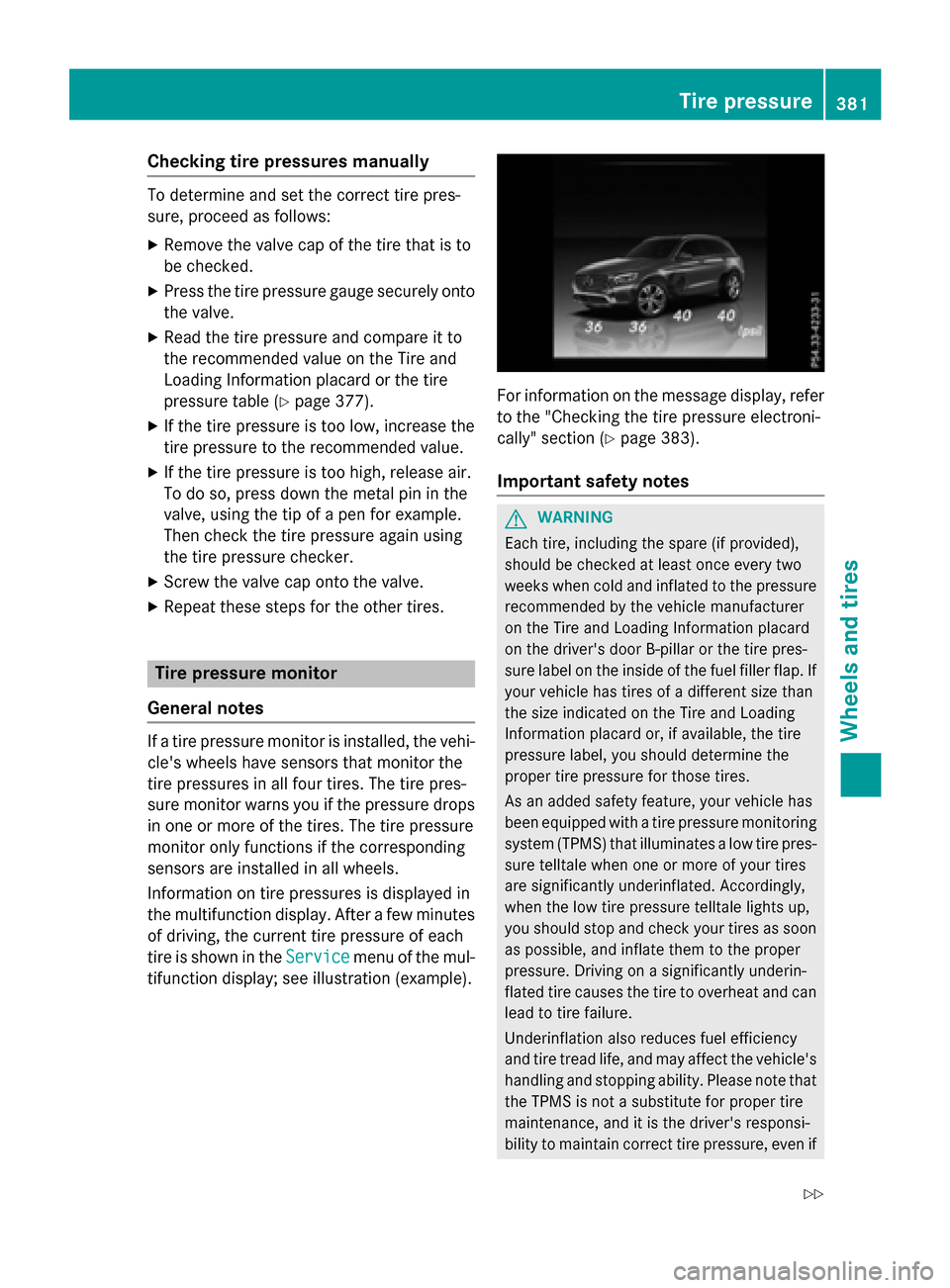
Information on tire pressures is displayed in
the multifunction display. After a few minutes
of driving, the current tire pressure of each
tire is shown in the Service
menu of the mul-
tifunction display; see illustration (example).
For information on the message display, refer
to the "Checking the tire pressure electroni-
cally" section (
Ypage 383).
Important safety notes
GWARNING
Each tire, including the spare (if provided),
should be checked at least once every two
weeks when cold and inflated to the pressure recommended by the vehicle manufacturer
on the Tire and Loading Information placard
on the driver's door B-pillar or the tire pres-
sure label on the inside of the fuel filler flap. If
your vehicle has tires of a different size than
the size indicated on the Tire and Loading
Information placard or, if available, the tire
pressure label, you should determine the
proper tire pressure for those tires.
As an added safety feature, your vehicle has
been equipped with a tire pressure monitoring
system (TPMS) that illuminates a low tire pres-
sure telltale when one or more of your tires
are significantly underinflated. Accordingly,
when the low tire pressure telltale lights up,
you should stop and check your tires as soon
as possible, and inflate them to the proper
pressure. Driving on a significantly underin-
flated tire causes the tire to overheat and can
lead to tire failure.
Underinflation also reduces fuel efficiency
and tire tread life, and may affect the vehicle's
handling and stopping ability. Please note thatthe TPMS is not a substitute for proper tire
maintenance, and it is the driver's responsi-
bility to maintain correct tire pressure, eve n if
Tire pressure381
Wheels and tires
Z
Page 395 of 418

DOT (Department of Transportation)
DOT-markedtires fulfill th erequirements of
th e U S Departmen tof Transportation .
Normal occupant weigh t
The number of occupant sfo rwhic hth evehi-
cle is designed multiplie dby 68 kilograms
(15 0lbs) .
Unifor mTire Qualit yGrading Standards
A uniform standard to grade th equalit yof
tires wit hregards to tread quality, tire traction
and temperature characteristics .The qualit y
gradin gassessmen tis made by th emanufac -
turer following specification sfrom th eU.S.
government. The ratings are molded into th e
sidewall of th etire.
Recommended tire pressure s
The recommended tire pressur eapplies to
th etires mounted at th efactory.
The Tir eand Loadin gInformation placard con-
tains th erecommended tire pressures fo r
cold tires on afull yloade dvehicl eand fo rth e
maximum permissibl evehicl espeed.
The tire pressur etable contain sth erecom-
mended pressures fo rcold tires fo rvarious
operating conditions, i.e. differin gload and
speed conditions.
Increased vehicle weigh tdu eto optiona l
equipment
The combine dweight of all standard and
optional equipmen tavailable fo rth evehicle,
regardless of whether it is a
ctually installed
on th evehicl eor not.
Ri m
This is th epart of th ewhee lon whic hth etire
is mounted.
GAW R(Gross Axle Weight Rating)
The GAW Ris th emaximum gross axl eweight
rating. The actual load on an axl emus tnever
exceed th egross axl eweight rating. The
gross axl eweight ratin gcan be found on th e
vehicl eidentification plat eon th eB-pillar on
th edriver's side . Speed rating
The speed ratin
gis part of th etire identifica-
tion .It specifies th espeed range fo rwhic hth e
tire is approved.
GV W(Gross Vehicle Weight )
The gross vehicl eweight includes th eweight
of th evehicl eincludin gfuel ,tools ,th espar e
wheel, accessories installed ,occupants, lug-
gage and th edrawbar noseweight ,if applica-
ble. The gross vehicl eweight mus tno texceed
th egross vehicl eweight ratin gGVWR as
specified on th evehicl eidentification plat eon
th eB-pillar on th edriver's side .
GVWR (Gross Vehicle Weight Rating)
The GVWR is th emaximum permissibl egross
weight of afull yloade dvehicl e(the weight of
th evehicl eincludin gall accessories, occu-
pants ,fuel, luggage and th edrawbar nose-
weight ,if applicable). The gross vehicl e
weight ratin gis specified on th
eve
hicl eiden -
tification plat eon th eB-pillar on th edriver's
side .
Maximum loaded vehicle weigh t
The maximum weight is th esum of :
Rthecur bweight of th evehicl e
Rtheweight of th eaccessories
Rth eload limi t
Rtheweight of th efactory installed optional
equipmen t
Kilopascal (kPa)
Metric uni tfo rtire pressure. 6. 9kP acorre-
spond sto 1psi .Another uni tfo rtire pressur e
is bar. 10 0kilopascal s(kPa) are th eequiva-
len tof 1bar.
Load index
In addition to th eload-bearin gindex ,th eload
index may also be imprinte don th esidewall of
th etire. This specifies th eload-bearin gcapa-
cit ymor eprecisely.
All about wheels and tires39 3
Wheels and tires
Z
Page 396 of 418

Curb weight
The weight of a vehicle with standard equip-
ment including the maximum capacity of fuel,
oil and coolant. It also includes the air-condi-
tioning system and optional equipment if
these are installed in the vehicle, but does not
include passengers or luggage.
Maximum load rating
The maximum tire load is the maximum per-
missible weight in kilograms or lbs for which a
tire is approved.
Maximum permissible tire pressure
Maximum permissible tire pressure for one
tire.
Maximum load on one tire
Maximum load on one tire. This is calculated
by dividing the maximum axle load of one axle
by two.
PSI (pounds per square inch)
A standard unit of measure for tire pressure.
Aspect ratio
Relationship between tire height and tire
width in percent.
Tire pressure
This is pressure inside the tire applying an
outward force to each square inch of the tire's
surface. The tire pressure is specified in
pounds per square inch (psi), in kilopascal
(kPa) or in bar. The tire pressure should only
be corrected when the tires are cold.
Cold tire pressure
The tires are cold:
Rif the vehicle has been parked with the tires
out of direct sunlight for at least three
hours and
Rif the vehicle has not been driven further
than 1 mile (1.6 km) Tread
The part of the tire that comes into contact
with the road.
Bead
The tire bead ensures that the tire sit
s
securely on t
he wheel. There are several steel
wires in the bead to prevent the tire from
coming loose from the wheel rim.
Sidewall
The part of the tire between the tread and the bead.
Weight of optional extras
The combined weight of those optional extras
that weigh more than the replaced standard
parts and more than 5 lbs (2.3 kg). These
optional extras, such as high-performance
brakes, level control, a roof rack or a high-
performance battery, are not included in the
curb weight and the weight of the accesso-
ries.
TIN (Tire Identification Number)
This is a unique identifier which can be used
by a tire manufacturer to identify tires, for
example for a product recall, and thus identify
the purchasers. The TIN is made up of the
manufacturer's identity code, tire size, tire
type code and the manufacturing date.
Load bearing index
The load bearing index (also load index) is a
code that contains the maximum load bearing
capacity of a tire.
Traction
Traction is the result of friction between the
tires and the road surface.
Treadwear indicators
Narrow bars (tread wear bars) that are dis-
tributed over the tire tread. If the tire tread is
level with the bars, the wear limit of áin
(1.6 mm) has been reached.
394All about wheels and tires
Wheels and tires