2016 MERCEDES-BENZ E-Class COUPE weight
[x] Cancel search: weightPage 207 of 318
Display messagesPossible causes/consequences andMSolutions
or
Rthefront-passenger seat is unoccupied
The system may detec tobjects or force sapplyin gadditional weigh ton
th eseat .
GWARNIN G
The air bag may deploy unintentionally.
There is an increased ris kof injury.
XPull ove rand stop th evehicl esafely as soo nas possible, payin g
attention to roa dand traffic conditions.
XSecur eth evehicl eagainst rollin gaway (Ypage 138).
XSwitchth eignition off .
XOpenth efront-passenger door .
XRemove thechild and th echild restrain tsystem from th efront-
passenger seat .
XMakesur ethat there are no objects on th eseat addin gto th e
weight.
The system may otherwise detec tth eadditional weigh tand inter-
pre tth eseat occupant's weigh tas greate rthan it actually is.
XKee pth eseat unoccupied ,close th efront-passenger door and
switch on th eignition .
XObserveth ePASSENGER AI RBA GOF Findicator lamp in th ecenter
console and th emultifunction display and chec kth efollowing:
Seat unoccupied and ignition switched on :
Raself-diagnosis is carrie dout .The PASSENGER AI RBA GOF Fand
PASSENGER AI RBA GON indicator lamp smus tligh tup simultane -
ousl yfor approximately six seconds
Rth ePASSENGER AI RBA GOF Findicator lamp mus tthen ligh tup and
remain lit after th eself-diagnosis .If th eindicator lamp is on ,OCS
has disabled th efront-passenger fron tair bag (
Ypage 49)
RtheFrontPassengerAirbagEnable dSeeOperator' sMan‐ualorFront Passenger Airbag Disabled See Operator' sManualdisplay messagesmus tno tbe shown in th emultifunction
display
XWait for aperiod of at least 60 seconds until th enecessar ysystem
checks hav ebeen completed.
XMak esur ethat th edisplay message sdo no tappear in th emulti-
function display.
If these condition sare fulfilled ,th efront-passenger seat can be occu-
pied again .Whether th ePASSENGER AI RBA GOF Findicator lamp
remain slit or goe sout depend son how OCS classifies th eoccupant .
If th econdition sare no tfulfilled ,th esystem is no toperating correctly.
XVisit aqualified specialist workshop immediately.
Observ eth eadditional information on OCS (
Ypage 49).
Display messages205
On-board computer and displays
Z
Page 237 of 318
Stowage areas
Loading guidelines
GWARNING
If objects, luggage or loads are not secured or
not secured sufficiently, they could slip, tip
over or be flung around and thereby hit vehicle
occupants. There is a risk of injury, particu-
larly in the event of sudden braking or a sud-
den change in direction.
Always store objects so that they cannot be
flung around. Secure objects, luggage or
loads against slipping or tipping before the
journey.
GWARNING
Combustion engines emit poisonous exhaust
gases such as carbon monoxide. Exhaust
gases can enter the vehicle interior if the
trunk lid is open when the engine is running,
especially if the vehicle is in motion. There is a
risk of poisoning.
Always switch off the engine before opening
the trunk lid. Never drive with the trunk lid
open.
GWARNING
The exhaust tail pipe and tail pipe trim can
become very hot. If you come into contact
with these parts of the vehicle, you could burn
yourself. There is a risk of injury.
Always be particularly careful around the
exhaust tail pipe and the tail pipe trim. Allow
these components to cool down before touch-
ing them.
The handling characteristics of a laden vehicle
are dependent on the distribution of the load
within the vehicle. For this reason, you should
observe the following notes when transporting a
load:
RNever exceed the maximum permissible
gross vehicle mass or the gross axle weight
rating for the vehicle (including occupants).
The values are specified on the vehicle iden- tification plate on the B-pillar of the driver's
door.
RThe trunk is the preferred place to carry
objects.
RPosition heavy loads as far forwards as pos-
sible and as low down in the trunk as possible.
RThe load must not protrude above the upper
edge of the seat backrests.
RAlways place the load against the rear or front
seat backrests. Make sure that the seat
backrests are securely locked into place.
RAlways place the load behind unoccupied
seats if possible.
RUse the cargo tie-down rings and the parcel
nets to transport loads and luggage.
RUse cargo tie-down rings and fastening mate-
rials appropriate for the weight and size of the
load.
RSecure the load with sufficiently strong and
wear-resistant tie-downs. Pad sharp edges forprotection.
Stowage spaces
Important safety notes
GWARNING
If objects in the passenger compartment are
stowed incorrectly, they can slide or be
thrown around and hit vehicle occupants. In
addition, cupholders, open stowage spaces
and mobile phone brackets cannot always
retain all objects they contain. There is a risk of injury, particularly in the event of sudden
braking or a sudden change in direction.
RAlways stow objects so that they cannot be
thrown around in such situations.
RAlways make sure that objects do not pro-
trude from stowage spaces, parcel nets or
stowage nets.
RClose the lockable stowage spaces before
starting a journey.
RAlways stow and secure heavy, hard, poin-
ted, sharp-edged, fragile or bulky objects in
the trunk.
Observe the loading guidelines (
Ypage 235).
Stowage areas235
Stowage and features
Z
Page 278 of 318

XStart the engine of the donor vehicle and run it at idling speed.
XConnect negative terminal?of donor battery Bto ground point Aof your vehicle using the
jumper cable, connecting the jumper cable to battery of other vehicle Bfirst.
XStart the engine.
XBefore disconnecting the jumper cables, let the engine run for several minutes.
XFirst, remove the jumper cables from ground point Aand negative terminal ?, then from pos-
itive clamp ;and positive terminal =. Begin each time at the contacts on your own vehicle first.
XClose cover:of positive clamp ;after removing the jumper cables.
XHave the battery checked at a qualified specialist workshop.
Jump-starting is not considered to be a normal operating condition.
iJumper cables and further information regarding jump-starting can be obtained at any qualified
specialist workshop.
Towing and tow-starting
Important safety notes
GWARNING
Functions relevant to safety are restricted or
no longer available if:
Rthe engine is not running.
Rthe brake system or the power steering is
malfunctioning.
Rthere is a malfunction in the voltage supply or the vehicle's electrical system.
If your vehicle is being towed, much more
force may be necessary to steer or brake.
There is a risk of an accident.
In such cases, use a tow bar. Before towing,
make sure that the steering moves freely.
GWARNING
When towing or tow-starting another vehicle
and its weight is greater than the permissible
gross weight of your vehicle, the:
Rthe towing eye could detach itself
Rthe vehicle/trailer combination could roll-
over.
There is a risk of an accident.
When towing or tow-starting another vehicle,
its weight should not be greater than the per- missible gross weight of your vehicle. Details on the permissible gross vehicle weight
of your vehicle can be found on the vehicle iden-
tification plate (
Ypage 307).
!When COLLISION PREVENTION ASSIST
PLUS, DISTRONIC PLUS or the HOLD function
is activated, the vehicle brakes automatically
in certain situations.
To avoid damage to the vehicle, deactivate
these systems in the following or similar sit-
uations:
Rwhen towing the vehicle
Rin the car wash
!Only secure the tow rope or tow bar at the
towing eyes. Otherwise, the vehicle could be
damaged.
!Do not use the towing eye for recovery, this
could damage the vehicle. If in doubt, recover
the vehicle with a crane.
!When towing, pull away slowly and
smoothly. If the tractive power is too high, the
vehicles could be damaged.
!Do not tow with sling-type equipment. This
could damage the vehicle.
!On vehicles with KEYLESS-GO, use the
SmartKey instead of the Start/Stop button.
Turn the SmartKey to position 2in the ignition
lock and shift the automatic transmission to
N. Then, turn the SmartKey back to 0and
leave it in the ignition lock.
!The vehicle can be towed a maximum of
30 miles (50km). The towing speed of 30 mph
(50 km/h) must not be exceeded.
276Towing and tow-starting
Breakdown assistance
Page 279 of 318
If the vehicle has to be towed more than
30 miles (50km), the entire vehicle must be
raised and transported.
!If you tow or tow-start another vehicle, its
weight must not exceed the maximum per-
missible gross vehicle weight of your vehicle.
It is better to have the vehicle transported than
to have it towed away.
If the vehicle has suffered transmission damage,
have it transported on a transporter or trailer.
The automatic transmission must be in position
N when the vehicle is being towed.
The battery must be connected and charged.
Otherwise, you:
Rcannot turn the SmartKey to position 2in the
ignition lock
Rcannot shift the automatic transmission to
position N
In the event of damage to the electrical sys-
tem
If the battery is defective, the automatic trans-
mission will be locked in position P. To shift the
automatic transmission to position N, you must
provide power to the vehicle's electrical system
in the same way as when jump-starting
(
Ypage 274).
Have the vehicle transported on a transporter or
trailer.
Disarm the automatic locking feature before the
vehicle is towed (
Ypage 79). You could other-
wise be locked out when pushing or towing the
vehicle.
Installing/removing the towing eye
Installing the towing eye
GWARNING
The exhaust tail pipe may be very hot. There is
a risk of burns when removing the rear cover.
Do not touch the exhaust pipe. Take particular
care when removing the rear cover.
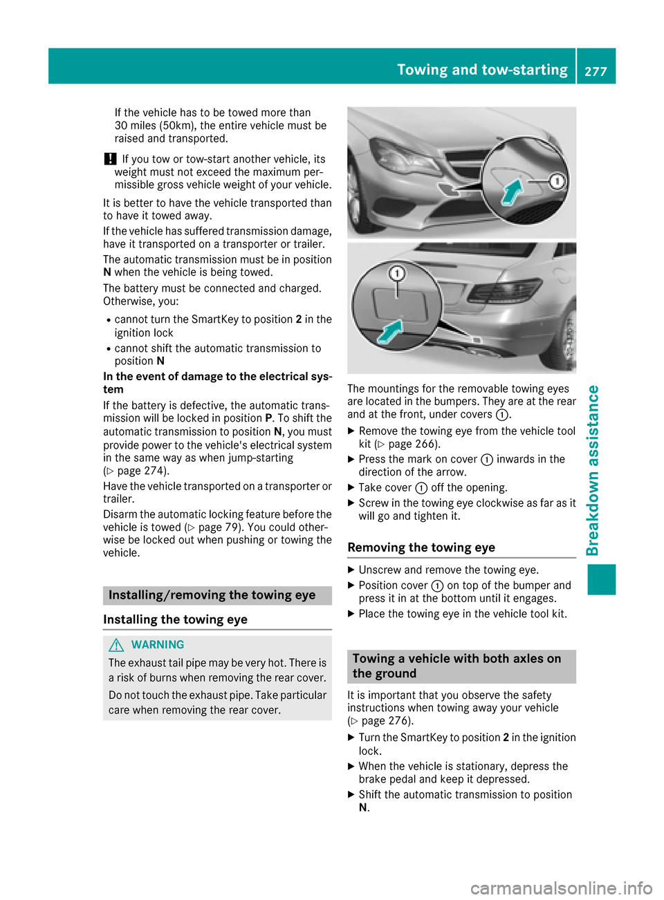
The mountings for the removable towing eyes
are located in the bumpers. They are at the rear
and at the front, under covers :.
XRemove the towing eye from the vehicle tool
kit (Ypage 266).
XPress the mark on cover:inwards in the
direction of the arrow.
XTake cover :off the opening.
XScrew in the towing eye clockwise as far as it
will go and tighten it.
Removing the towing eye
XUnscrew and remove the towing eye.
XPosition cover :on top of the bumper and
press it in at the bottom until it engages.
XPlace the towing eye in the vehicle tool kit.
Towing a vehicle with both axles on
the ground
It is important that you observe the safety
instructions when towing away your vehicle
(
Ypage 276).
XTurn the SmartKey to position 2in the ignition
lock.
XWhen the vehicle is stationary, depress the
brake pedal and keep it depressed.
XShift the automatic transmission to position
N.
Towing and tow-starting277
Breakdown assistance
Z
Page 292 of 318
You can find more tire pressure values for
various operating conditions in the tire pres-
sure table inside the fuel filler flap
(
Ypage 284).
XMake sure that the tire pressure is correct on
all four wheels.
XMake sure that the SmartKey is in position2
in the ignition lock.
XPress the =or; button on the steering
wheel to select the Servicemenu.
XPress the9or: button to select
Tire Pressure.
XPress the abutton.
The multifunction display shows the current
tire pressure for the individual tires or the
Tire pressures will be displayed
after driving a few minutesmessage.
XPress the :button.
The UseCurrentPressuresasNewRef‐erenceValuesmessage appears in the mul-
tifunction display.
If you wish to confirm the restart:
XPress the abutton.
The TirePress.MonitorRestartedmes-
sage appears in the multifunction display.
After driving for a few minutes, the system
checks whether the current tire pressures are within the specified range. The new tire pres-
sures are then accepted as reference values
and monitored.
If you wish to cancel the restart:
XPress the %button.
The tire pressure values stored at the last
restart will continue to be monitored.
Loading the vehicle
Instruction labels for tires and loads
GWARNING
Overloaded tires can overheat, causing a
blowout. Overloaded tires can also impair the steering and driving characteristics and lead
to brake failure. There is a risk of accident.
Observe the load rating of the tires. The load
rating must be at least half of the GAWR of
your vehicle. Never overload the tires by
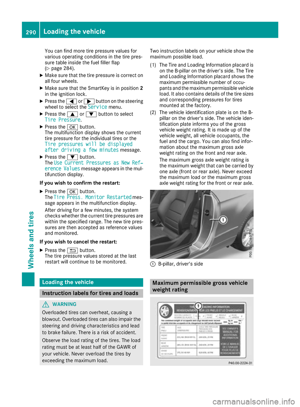
exceeding the maximum load. Two instruction labels on your vehicle show the
maximum possible load.
(1) The Tire and Loading Information placard is on the B-pillar on the driver's side. The Tire
and Loading Information placard shows the
maximum permissible number of occu-
pants and the maximum permissible vehicle
load. It also contains details of the tire sizes
and corresponding pressures for tires
mounted at the factory.
(2) The vehicle identification plate is on the B- pillar on the driver's side. The vehicle iden-
tification plate informs you of the gross
vehicle weight rating. It is made up of the
vehicle weight, all vehicle occupants, the
fuel and the cargo. You can also find infor-
mation about the maximum gross axle
weight rating on the front and rear axle.
The maximum gross axle weight rating is
the maximum weight that can be carried by
one axle (front or rear axle). Never exceed
the maximum load or the maximum gross
axle weight rating for the front or rear axle.
:B-pillar, driver's side
Maximum permissible gross vehicle
weight rating
290Loading the vehicle
Wheels and tires
Page 293 of 318

XSpecification for maximum gross vehicle
weight:is listed in the Tire and Loading
Information placard: "The combined weight of occupants and cargo should never exceed
XXX kilograms or XXX lbs."
The gross weight of all vehicle occupants, load
and luggage must not exceed the specified
value.
iThe specifications shown on the Tire and
Loading Information placard in the illustration are examples. The maximum permissible
gross vehicle weight rating is vehicle-specific
and may differ from that in the illustration.
You can find the valid maximum permissible
gross vehicle weight rating for your vehicle on
the Tire and Loading Information placard.
Number of seats
Maximum number of seats :indicates the
maximum number of occupants allowed to
travel in the vehicle. This information can be
found on the Tire and Loading Information plac-
ard.
iThe specifications shown on the Tire and
Loading Information placard in the illustration
are examples. The number of seats is vehicle-
specific and can differ from the details shown.
The number of seats in your vehicle can be
found on the Tire and Loading Information
placard.
Determining the correct load limit
Step-by-step instructions
The following steps have been developed as
required of all manufacturers under Title 49,
Code of U.S. Federal Regulations, Part 575 pur- suant to the "National Traffic and Motor Vehicle
Safety Act of 1966".
XStep 1: Locate the statement "The combined
weight of occupants and cargo should never
exceed XXX kg or XXX lbs." on your vehicle’s
Tire and Loading Information placard.
XStep 2: Determine the combined weight of
the driver and passengers that will be riding in your vehicle.
XStep 3: Subtract the combined weight of the
driver and passengers from XXX kilograms or
XXX lbs.
XStep 4: The resulting figure equals the avail-
able amount of cargo and luggage load capa-
city. For example, if the "XXX" amount equals
1400 lbs and there will be five 150-lb pas-
sengers in your vehicle, the amount of avail-
able cargo and luggage load capacity is
650 lbs (1400 - 750 (5 x 150) = 650 lbs).
XStep 5: Determine the combined weight of
luggage and cargo being loaded on the vehi-
cle. That weight may not safely exceed the
available cargo and luggage load capacity cal- culated in step 4.
Loading the vehicle291
Wheels and tires
Z
Page 294 of 318
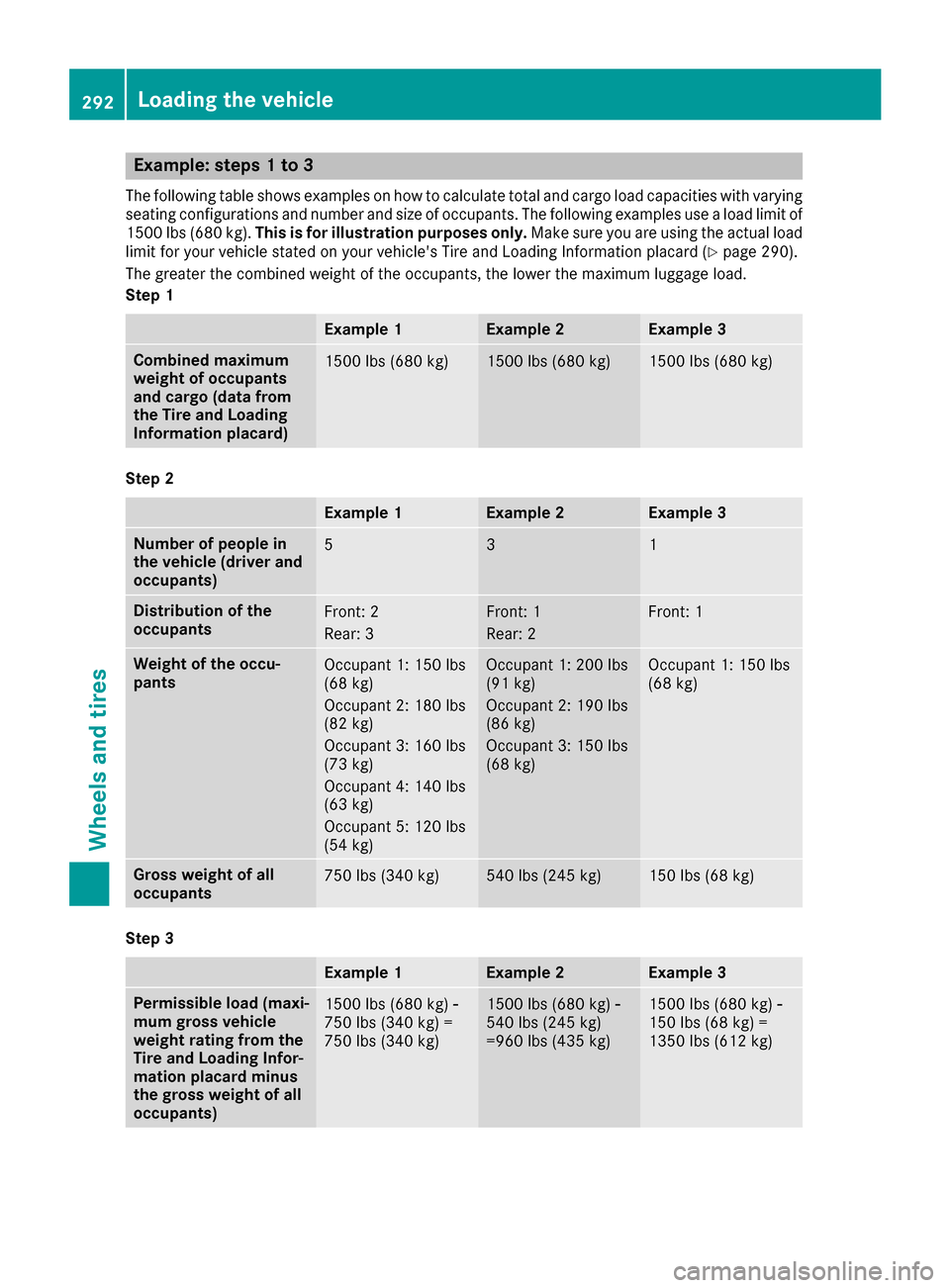
Example: steps 1 to 3
The following table shows examples on how to calculate total and cargo load capacities with varying
seating configurations and number and size of occupants. The following examples use a load limit of
1500 lbs (680 kg).This is for illustration purposes only. Make sure you are using the actual load
limit for your vehicle stated on your vehicle's Tire and Loading Information placard (
Ypage 290).
The greater the combined weight of the occupants, the lower the maximum luggage load.
Step 1
Example 1Example 2Example 3
Combined maximum
weight of occupants
and cargo (data from
the Tire and Loading
Information placard)1500 lbs (680 kg)1500 lbs (680 kg)1500 lbs (680 kg)
Step 2
Example 1Example 2Example 3
Number of people in
the vehicle (driver and
occupants)531
Distribution of the
occupantsFront: 2
Rear: 3Front: 1
Rear: 2Front: 1
Weight of the occu-
pantsOccupant 1: 150 lbs
(68 kg)
Occupant 2: 180 lbs
(82 kg)
Occupant 3: 160 lbs
(73 kg)
Occupant 4: 140 lbs
(63 kg)
Occupant 5: 120 lbs
(54 kg)Occupant 1: 200 lbs
(91 kg)
Occupant 2: 190 lbs
(86 kg)
Occupant 3: 150 lbs
(68 kg)Occupant 1: 150 lbs
(68 kg)
Gross weight of all
occupants750 lbs (340 kg)540 lbs (245 kg)150 lbs (68 kg)
Step 3
Example 1Example 2Example 3
Permissible load (maxi-
mum gross vehicle
weight rating from the
Tire and Loading Infor-
mation placard minus
the gross weight of all
occupants)1500 lbs (680 kg) Ò
750 lbs (340 kg) =
750 lbs (340 kg)1500 lbs (680 kg) Ò
540 lbs (245 kg)
=960 lbs (435 kg)1500 lbs (680 kg) Ò
150 lbs (68 kg) =
1350 lbs (612 kg)
292Loading the vehicle
Wheels and tires
Page 295 of 318

Vehicle identification plate
Even if you have calculated the total cargo care-
fully, you should still make sure that the gross
vehicle weight rating and the gross axle weight
rating are not exceeded. Details can be found on
the vehicle identification plate on the B-pillar on
the driver's side of the vehicle (
Ypage 290).
Permissible Gross Vehicle Weight Rating
(GVWR): the gross weight of the vehicle, all pas-
sengers, load and trailer load/noseweight (if
applicable) must not exceed the permissible
gross vehicle weight.
Gross Axle Weight Rating (GAWR): the maxi-
mum permissible weight that can be carried by
one axle (front or rear axle).
To ensure that your vehicle does not exceed the
maximum permissible values (gross vehicle
weight and maximum gross axle weight rating),
have your loaded vehicle (including driver, occu-
pants, cargo, and full trailer load if applicable)
weighed on a suitable vehicle weighbridge.
All about wheels and tires
Uniform Tire Quality Grading Stand-
ards
Overview of Tire Quality Grading Stand-
ards
Uniform Tire Quality Grading Standards are U.S.
government specifications. Their purpose is to
provide drivers with uniform reliable information
on tire performance data. Tire manufacturers
have to grade tires using three performance fac- tors: :tread wear grade, ;traction grade and
= temperature grade. These regulations do not
apply to Canada. Nevertheless, all tires sold in
North America are provided with the corre- sponding quality grading markings on the side-
wall of the tire.
Quality grades can be found, where applicable,
on the tire sidewall between tread shoulder and
maximum section width.
Example:
RTreadwear grade:
200
RTraction grade:AA
RTemperature grade: A
All passenger car tires must conform to the stat-
utory safety requirements in addition to these
grades.
iThe actual values for tires are vehicle-spe-
cific and may deviate from the values in the
illustration.
Treadwear
The treadwear grade is a comparative rating
based on the wear rate of the tire when tested
under controlled conditions on a specified U.S.
government course. For example, a tire graded
150 would wear one and one-half times as well
on the government course as a tire graded 100.
The relative performance of tires depends upon the actual conditions of their use, however, and
may depart significantly from the norm due to
variations in driving habits, service practices
and differences in road characteristics and cli-
mate.
Traction
GWARNING
The traction grade assigned to this tire is
based on straight-ahead braking traction
tests, and does not include acceleration, cor-
nering, hydroplaning, or peak traction char-
acteristics.
!Avoid wheelspin. This can lead to damage to
the drive train.
The traction grades – from highest to lowest –
are AA, A, B and C. Those grades represent the
tire's ability to stop on wet pavement as meas-
ured under controlled conditions on specified
government test surfaces of asphalt and con-
crete. A tire marked C may have poor traction
performance.
The safe speed on a wet, snow covered or icy
road is always lower than on dry road surfaces.
All about wheels and tires293
Wheels and tires
Z