2016 MERCEDES-BENZ CLA COUPE ignition
[x] Cancel search: ignitionPage 188 of 345

vehicle with guide lines in the multimedia sys-
tem display.
The area behind the vehicle is displayed as a
mirror image, as in the rear-view mirror.
i The text shown in the multimedia system
display depends on the language setting. The following are examples of reversing camera
messages in the multimedia system display.
See the notes on cleaning (Y page 289).
Important safety notes The reversing camera is only an aid. It is not a
substitute for your attention to the immediate
surroundings. The responsibility for safe
manoeuvring and parking remains with you.
Make sure that there are no persons, animals or
objects in range while manoeuvring and parking.
The reversing camera will not function or will
function only in a limited manner:
R If the boot lid is open
R In heavy rain, snow or fog
R At night or in very dark places
R If the camera is exposed to very bright light
R If the area is lit by fluorescent lamps or LED
lighting (the display may flicker)
R If there is a sudden change in temperature,
e.g. when driving into a heated garage in win- ter
R If the camera lens is dirty or obstructed.
Observe the notes on cleaning
(Y page 289)
R If the rear of your vehicle is damaged. In this
case, have the camera position and setting
checked at a qualified specialist workshop
The field of vision and other functions of the
reversing camera may be restricted due to addi-
tional accessories on the rear of the vehicle (e.g. licence plate holder, bicycle rack). Activating/deactivating the reversing
camera X
To activate: make sure that the key is in
position 2in the ignition lock.
X Make sure that the Activation by R gear Activation by R gear
function is selected in the multimedia system; see the Digital Owner's Manual.
X Engage reverse gear.
The area behind the vehicle is shown with
guide lines in the multimedia system display.
The image from the reversing camera is avail-
able throughout the manoeuvring process.
X To switch the function mode for vehicles
with trailer tow hitch: using the controller,
select symbol :for the "Reverse parking"
function or symbol ;for "Coupling up a
trailer".
The symbol of the selected function is high-
lighted.
To deactivate: the reversing camera deacti-
vates if you shift the transmission to Por after
driving forwards a short distance.
Messages in the multimedia system dis-
play The reversing camera may show a distorted view
of obstacles, show them incorrectly or not at all.
Obstacles are not shown by the reversing cam-
era in the following locations:
R Very close to the rear bumper
R Under the rear bumper
R In the area immediately above the recessed
handle on the boot lid
! Objects not at ground level may appear to
be further away than they actually are, e.g.:
R the bumper of a parked vehicle
R the drawbar of a trailer Driving systems
185Driving and parking Z
Page 196 of 345
up to a speed of 30 km/h. At speeds above
30 km/h, the indicator lamp goes out and Blind
Spot Assist is operational.
If a vehicle is detected within the monitoring
range of Blind Spot Assist at speeds above
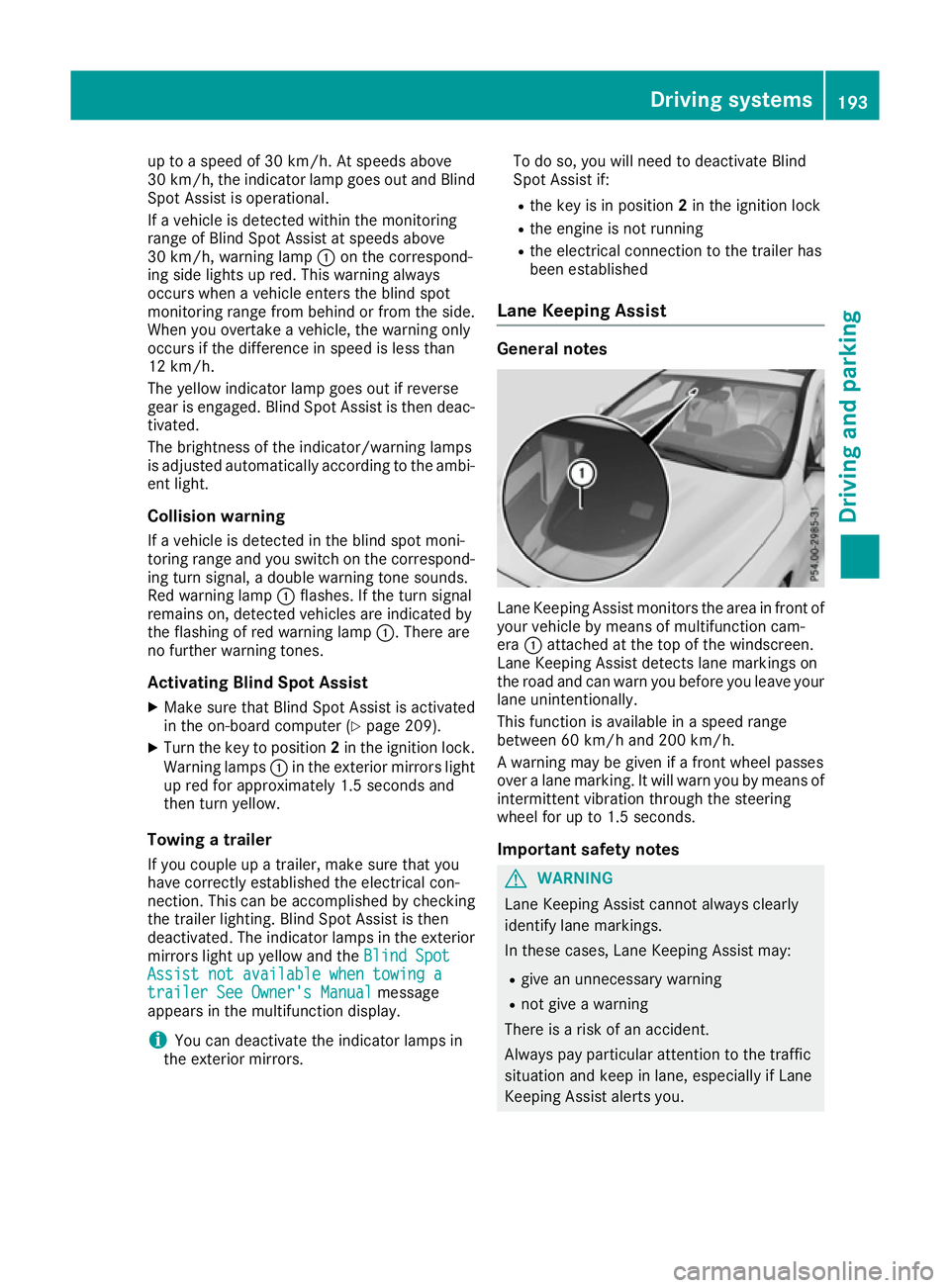
30 km/h, warning lamp :on the correspond-
ing side lights up red. This warning always
occurs when a vehicle enters the blind spot
monitoring range from behind or from the side.
When you overtake a vehicle, the warning only
occurs if the difference in speed is less than
12 km/h.
The yellow indicator lamp goes out if reverse
gear is engaged. Blind Spot Assist is then deac- tivated.
The brightness of the indicator/warning lamps
is adjusted automatically according to the ambi-
ent light.
Collision warning
If a vehicle is detected in the blind spot moni-
toring range and you switch on the correspond-
ing turn signal, a double warning tone sounds.
Red warning lamp :flashes. If the turn signal
remains on, detected vehicles are indicated by
the flashing of red warning lamp :. There are
no further warning tones.
Activating Blind Spot Assist X Make sure that Blind Spot Assist is activated
in the on-board computer (Y page 209).
X Turn the key to position 2in the ignition lock.
Warning lamps :in the exterior mirrors light
up red for approximately 1.5 seconds and
then turn yellow.
Towing a trailer
If you couple up a trailer, make sure that you
have correctly established the electrical con-
nection. This can be accomplished by checking
the trailer lighting. Blind Spot Assist is then
deactivated. The indicator lamps in the exterior
mirrors light up yellow and the Blind Spot
Blind Spot
Assist not available when towing a Assist not available when towing a
trailer See Owner's Manual trailer See Owner's Manual message
appears in the multifunction display.
i You can deactivate the indicator lamps in
the exterior mirrors. To do so, you will need to deactivate Blind
Spot Assist if:
R the key is in position 2in the ignition lock
R the engine is not running
R the electrical connection to the trailer has
been established
Lane Keeping Assist General notes
Lane Keeping Assist monitors the area in front of
your vehicle by means of multifunction cam-
era :attached at the top of the windscreen.
Lane Keeping Assist detects lane markings on
the road and can warn you before you leave your lane unintentionally.
This function is available in a speed range
between 60 km/h and 200 km/h.
A warning may be given if a front wheel passes
over a lane marking. It will warn you by means of intermittent vibration through the steering
wheel for up to 1.5 seconds.
Important safety notes G
WARNING
Lane Keeping Assist cannot always clearly
identify lane markings.
In these cases, Lane Keeping Assist may:
R give an unnecessary warning
R not give a warning
There is a risk of an accident.
Always pay particular attention to the traffic
situation and keep in lane, especially if Lane
Keeping Assist alerts you. Driving systems
193Driving and parking Z
Page 201 of 345
there is an increased risk of an accident and
injury.
Only release the ball coupling if the pivoting
range is unobstructed. Always make sure that the ball coupling engages when folding in.
i Fold the ball coupling in if you are not using
the trailer tow hitch.
X Make sure that the vehicle is stationary and
the trailer cables are disconnected.
X Place the protective cap on the ball coupling.
i The release wheel is located behind the left-
hand side trim panel in the luggage compart- ment.
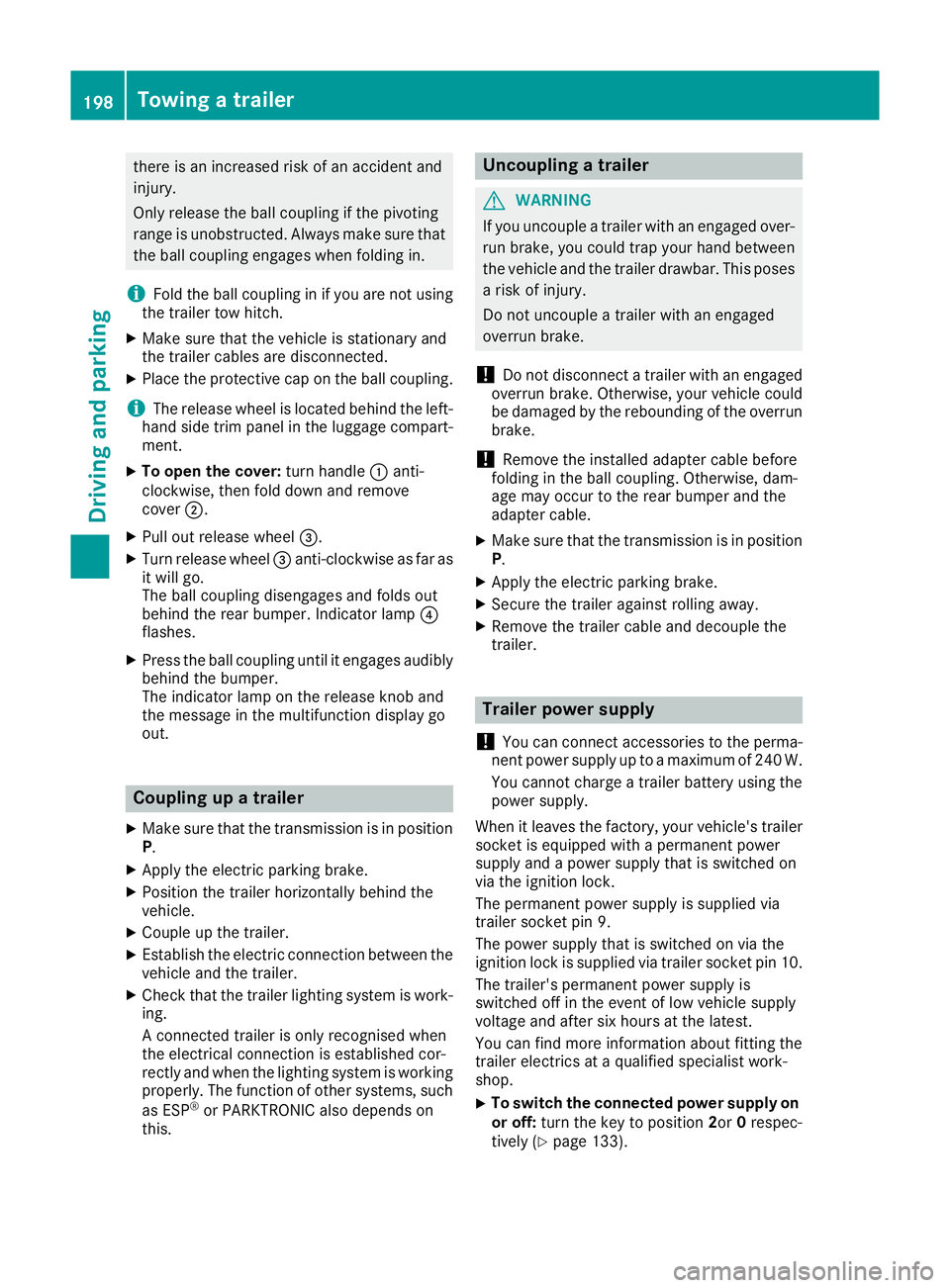
X To open the cover: turn handle:anti-
clockwise, then fold down and remove
cover ;.
X Pull out release wheel =.
X Turn release wheel =anti-clockwise as far as
it will go.
The ball coupling disengages and folds out
behind the rear bumper. Indicator lamp ?
flashes.
X Press the ball coupling until it engages audibly
behind the bumper.
The indicator lamp on the release knob and
the message in the multifunction display go
out. Coupling up a trailer
X Make sure that the transmission is in position
P.
X Apply the electric parking brake.
X Position the trailer horizontally behind the
vehicle.
X Couple up the trailer.
X Establish the electric connection between the
vehicle and the trailer.
X Check that the trailer lighting system is work-
ing.
A connected trailer is only recognised when
the electrical connection is established cor-
rectly and when the lighting system is working
properly. The function of other systems, such
as ESP ®
or PARKTRONIC also depends on
this. Uncoupling a trailer
G
WARNING
If you uncouple a trailer with an engaged over- run brake, you could trap your hand between
the vehicle and the trailer drawbar. This poses a risk of injury.
Do not uncouple a trailer with an engaged
overrun brake.
! Do not disconnect a trailer with an engaged
overrun brake. Otherwise, your vehicle could
be damaged by the rebounding of the overrun brake.
! Remove the installed adapter cable before
folding in the ball coupling. Otherwise, dam-
age may occur to the rear bumper and the
adapter cable.
X Make sure that the transmission is in position
P.
X Apply the electric parking brake.
X Secure the trailer against rolling away.
X Remove the trailer cable and decouple the
trailer. Trailer power supply
! You can connect accessories to the perma-
nent power supply up to a maximum of 240 W.
You cannot charge a trailer battery using the
power supply.
When it leaves the factory, your vehicle's trailer
socket is equipped with a permanent power
supply and a power supply that is switched on
via the ignition lock.
The permanent power supply is supplied via
trailer socket pin 9.
The power supply that is switched on via the
ignition lock is supplied via trailer socket pin 10.
The trailer's permanent power supply is
switched off in the event of low vehicle supply
voltage and after six hours at the latest.
You can find more information about fitting the
trailer electrics at a qualified specialist work-
shop.
X To switch the connected power supply on
or off: turn the key to position 2or0respec-
tively (Y page 133). 198
Towing a trailerDriving an
d parking
Page 204 of 345
There is a short delay before a change in outside
temperature appears in the multifunction dis-
play. Coolant temperature gauge
G
WARNING
If you open the bonnet while the engine is
overheating or while there is a fire in the
engine compartment, you could come into
contact with hot gases or other leaking ser-
vice products. There is a danger of injury.
Allow an overheating engine to cool down
before opening the bonnet. If there is a fire in the engine compartment, leave the bonnet
closed and notify the fire brigade.
The coolant temperature gauge is in the instru-
ment cluster on the right-hand side (Y page 32).
Under normal operating conditions and with the correct coolant level, the coolant temperature
may rise to 120 †.
At high outside temperatures and when driving
in mountainous terrain, the coolant temperature may rise to the end of the scale. Operating the on-board computer
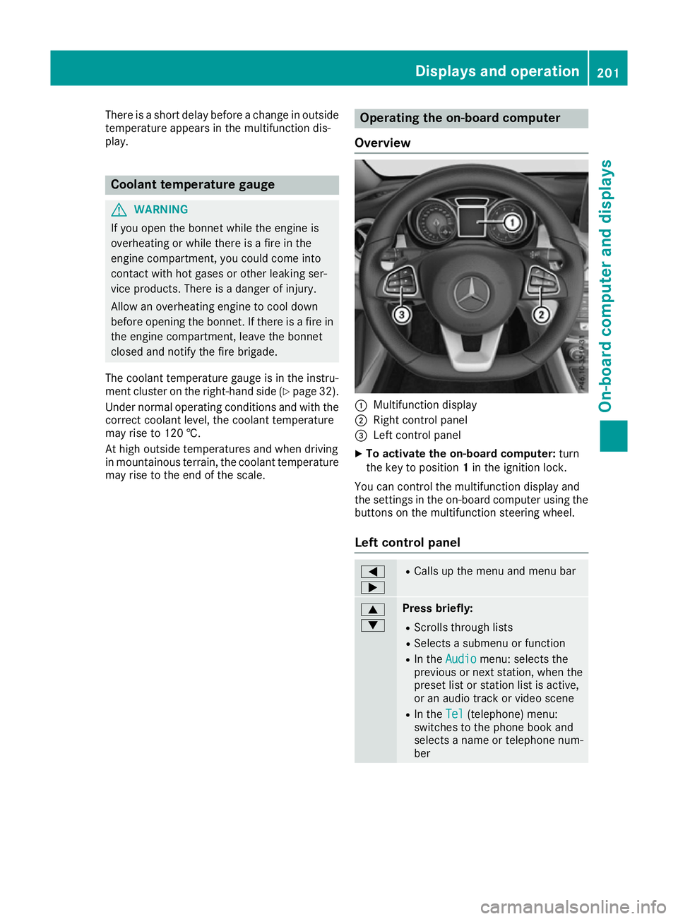
Overview :
Multifunction display
; Right control panel
= Left control panel
X To activate the on-board computer: turn
the key to position 1in the ignition lock.
You can control the multifunction display and
the settings in the on-board computer using the buttons on the multifunction steering wheel.
Left control panel =
; R
Calls up the menu and menu bar 9
: Press briefly:
R Scrolls through lists
R Selects a submenu or function
R In the Audio Audio menu: selects the
previous or next station, when the preset list or station list is active,
or an audio track or video scene
R In the Tel Tel(telephone) menu:
switches to the phone book and
selects a name or telephone num-
ber Displays and operation
201On-board computer and displays Z
Page 206 of 345
The following messages may appear in the
multifunction display:
R ZGearshift recommendation for manual
transmission (Y page 143) or for automatic
transmission (shifting manually)
(Y page 150)
R j Parking Pilot (Y page 180)
R ¯ Cruise control (Y page 162)
R È Limiter (Y page 165)
R _ Adaptive Highbeam Assist
(Y page 109)
R è ECO start/stop function (Y page 137)
R ë HOLD function (Y page 172)
R 120 km/h!
120 km/h! Maximum permissible speed
exceeded (only for certain countries) Menus and submenus
Menu overview
Using the =or; button on the steering
wheel, open the menu bar.
Operating the on-board computer (Y page 201).
Depending on the equipment fitted in the vehi-
cle, you can call up the following menus:
R Trip Trip menu (Y page 203)
R Navi
Navi menu (navigation instructions)
(Y page 205)
R Audio
Audio menu (Y page 206)
R Tel
Tel menu (telephone) (Y page 207)
R Assist.
Assist. menu (assistance) (Y page 208)
R Serv.
Serv. menu (Y page 210)
R Settings
Settings menu (settings) (Y page 210)
R AMG
AMG menu (Mercedes-AMG vehicles)
(Y page 213)
The displays for the Audio
Audio,Navi
NaviandTel
Tel menus
may differ slightly to those in your vehicle.
The examples given in this Owner's Manual
apply to vehicles equipped with COMAND
Online. Trip menu
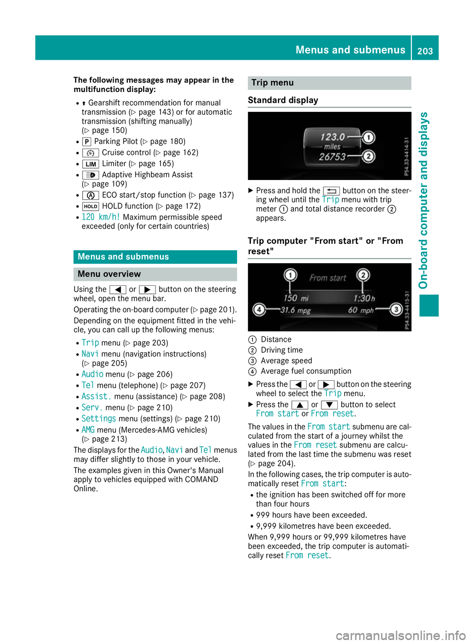
Standard display X
Press and hold the %button on the steer-
ing wheel until the Trip Tripmenu with trip
meter :and total distance recorder ;
appears.
Trip computer "From start" or "From
reset" :
Distance
; Driving time
= Average speed
? Average fuel consumption
X Press the =or; button on the steering
wheel to select the Trip Tripmenu.
X Press the 9or: button to select
From start
From start orFrom reset
From reset.
The values in the From
Fromstart
start submenu are cal-
culated from the start of a journey whilst the
values in the From reset From resetsubmenu are calcu-
lated from the last time the submenu was reset
(Y page 204).
In the following cases, the trip computer is auto-
matically reset From start
From start:
R the ignition has been switched off for more
than four hours
R 999 hours have been exceeded.
R 9,999 kilometres have been exceeded.
When 9,999 hours or 99,999 kilometres have
been exceeded, the trip computer is automati-
cally reset From reset From reset. Menus and submenus
203On-board computer and displays Z
Page 207 of 345
ECO display
The ECO display is not available in Mercedes-
AMG vehicles.
X Press the =or; button on the steering
wheel to select the Trip
Tripmenu.
X Press the 9or: button to select ECO
ECO
DISPLAY
DISPLAY.
If the ignition remains switched off for longer
than four hours, the ECO display will be auto-
matically reset.
Further information on the ECO display
(Y page 159).
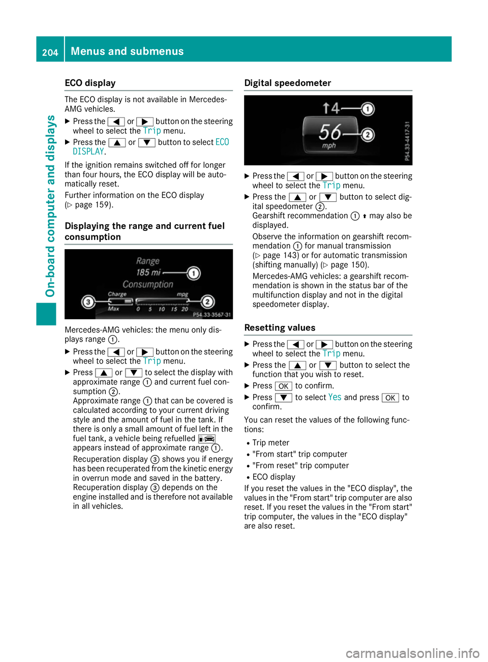
Displaying the range and current fuel
consumption Mercedes-AMG vehicles: the menu only dis-
plays range :.
X Press the =or; button on the steering
wheel to select the Trip Tripmenu.
X Press 9or: to select the display with
approximate range :and current fuel con-
sumption ;.
Approximate range :that can be covered is
calculated according to your current driving
style and the amount of fuel in the tank. If
there is only a small amount of fuel left in the
fuel tank, a vehicle being refuelled C
appears instead of approximate range :.
Recuperation display =shows you if energy
has been recuperated from the kinetic energy in overrun mode and saved in the battery.
Recuperation display =depends on the
engine installed and is therefore not available in all vehicles. Digital speedometer X
Press the =or; button on the steering
wheel to select the Trip Tripmenu.
X Press the 9or: button to select dig-
ital speedometer ;.
Gearshift recommendation :Zmay also be
displayed.
Observe the information on gearshift recom-
mendation :for manual transmission
(Y page 143) or for automatic transmission
(shifting manually) (Y page 150).
Mercedes-AMG vehicles: a gearshift recom-
mendation is shown in the status bar of the
multifunction display and not in the digital
speedometer display.
Resetting values X
Press the =or; button on the steering
wheel to select the Trip Tripmenu.
X Press the 9or: button to select the
function that you wish to reset.
X Press ato confirm.
X Press :to select Yes
Yesand press ato
confirm.
You can reset the values of the following func-
tions:
R Trip meter
R "From start" trip computer
R "From reset" trip computer
R ECO display
If you reset the values in the "ECO display", the
values in the "From start" trip computer are also
reset. If you reset the values in the "From start" trip computer, the values in the "ECO display"
are also reset. 204
Menus and submenusOn-board computer and displays
Page 217 of 345
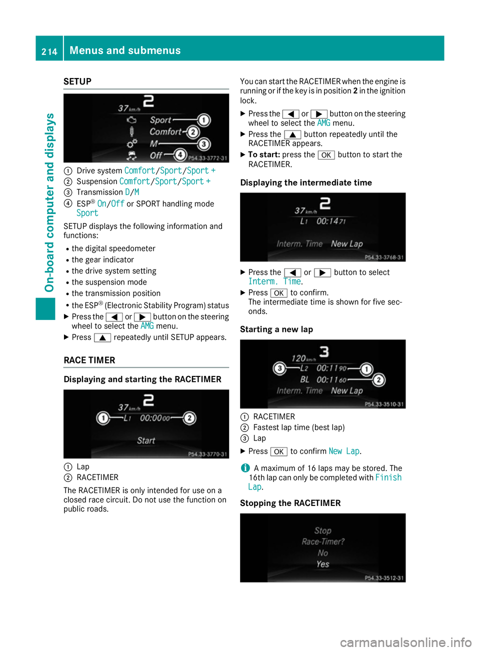
SETUP
:
Drive system Comfort
Comfort/SportSport/Sport +Sport +
; Suspension Comfort
Comfort/Sport Sport/Sport +Sport +
= Transmission D
D/M M
? ESP ®
On
On/Off Off or SPORT handling mode
Sport
Sport
SETUP displays the following information and
functions:
R the digital speedometer
R the gear indicator
R the drive system setting
R the suspension mode
R the transmission position
R the ESP ®
(Electronic Stability Program) status
X Press the =or; button on the steering
wheel to select the AMG
AMG menu.
X Press 9repeatedly until SETUP appears.
RACE TIMER Displaying and starting the RACETIMER
:
Lap
; RACETIMER
The RACETIMER is only intended for use on a
closed race circuit. Do not use the function on
public roads. You can start the RACETIMER when the engine is
running or if the key is in position 2in the ignition
lock.
X Press the =or; button on the steering
wheel to select the AMG
AMG menu.
X Press the 9button repeatedly until the
RACETIMER appears.
X To start: press the abutton to start the
RACETIMER.
Displaying the intermediate time X
Press the =or; button to select
Interm. Time
Interm. Time.
X Press ato confirm.
The intermediate time is shown for five sec-
onds.
Starting a new lap :
RACETIMER
; Fastest lap time (best lap)
= Lap
X Press ato confirm New Lap
New Lap.
i A maximum of 16 laps may be stored. The
16th lap can only be completed with Finish
Finish
Lap
Lap.
Stopping the RACETIMER 214
Menus and submenusOn-board computer and displays
Page 219 of 345
Display messages
Introduction
General notes Display messages appear in the multifunction display.
Display messages with graphic symbols are simplified in the Owner's Manual and may differ from
the symbols in the multifunction display.
Please respond in accordance with the display messages and follow the additional notes in this
Owner's Manual.
Certain display messages are accompanied by an audible warning tone or a continuous tone.
When the ignition is switched off, all display messages are deleted apart from some high-priority
display messages. Once the causes of the high-priority display messages have been rectified, these
display messages are deleted as well.
When you stop and park the vehicle, please observe the notes on:
R HOLD function (Y page 172)
R Parking (Y page 155)
Hiding display messages X
Press the aor% button on the steering wheel.
The multifunction display hides the display message.
The multifunction display shows high-priority display messages in red. Some high-priority display
messages cannot be hidden.
The multifunction display shows these messages continuously until the causes for the messages
have been remedied.
Message memory The on-board computer saves certain display messages in the
message memory. You can call up
the display messages:
X Press the =or; button on the steering wheel to select the Service
Service menu.
If there are display messages, the multifunction display shows 2 messages
2 messages, for example.
X Press the 9or: button to select the entry, e.g. 2 messages
2 messages.
X Press ato confirm.
X Press the 9or: button to scroll through the display messages. 216
Display
messagesOn-board computer and displays