2016 MERCEDES-BENZ C-Class SEDAN Vehicle level
[x] Cancel search: Vehicle levelPage 371 of 398

The tire pressure monitor has a yellow warning
lamp in the instrument cluster for indicating
pressure loss or a malfunction. Whether the
warning lamp flashes or lights up indicates
whether a tire pressure is too low or the tire
pressure monitor is malfunctioning:
Rif the warning lamp is lit continuously, the tire
pressure on one or more tires is significantly
too low. The tire pressure monitor is not mal-functioning.
Rif the warning lamp flashes for around a
minute and then remains lit constantly, the
tire pressure monitor is malfunctioning.
In addition to the warning lamp, a message
appears in the multifunction display. Observe
the information on display messages
(
Ypage 280).
It may take up to ten minutes for a malfunction of the tire pressure monitor to be indicated. A
malfunction will be indicated by the tire pres-
sure warning lamp flashing for approximately
one minute and then remaining lit. When the
malfunction has been rectified, the tire pressure
warning lamp goes out after a few minutes of
driving.
The tire pressure values indicated by the on-
board computer may differ from those meas-
ured at a gas station with a pressure gauge. The
tire pressures shown by the on-board computer
refer to those measured at sea level. At high
altitudes, the tire pressure values indicated by a
pressure gauge are higher than those shown by the on-board computer. In this case, do not
reduce the tire pressures.
The operation of the tire pressure monitor can
be affected by interference from radio transmit-
ting equipment (e.g. radio headphones, two-way
radios) that may be being operated in or near the vehicle.
Checking the tire pressure electroni-
cally
XMake sure that the SmartKey is in position 2
in the ignition lock (Ypage 146).
XUse ò on the steering wheel to call up the
list of menus.
XPress 9or: on the steering wheel to
select the Servicemenu.
XPress theabutton.
XPress 9or: to select Tire Pres‐sure.
XPress the abutton.
The current tire pressure of each tire is shown
in the multifunction display.
If the vehicle was parked for longer than
20 minutes, the following message appears:
Tire
pressurewillbedisplayedafterdriving a few minutes.
After a teach-in process, the tire pressure mon- itor automatically detects new wheels or new
sensors. As long as a clear allocation of the tire
pressure value to the individual wheels is not
possible, the Tire
PressureMonitorActivemessage is shown instead of the tire pressure
display. The tire pressures are already being
monitored.
Tire pressure monitor warning mes-
sages
If the tire pressure monitor detects a pressure
loss in one or more tires, a warning message is
shown in the multifunction display. The yellow
tire pressure warning lamp then lights up.
RIf thePlease Correct Tire Pressuremessage appears in the multifunction display,
the tire pressure in at least one tire is too low.
The tire pressure must be corrected when the
opportunity arises.
RIf the Check Tiresmessage appears in the
multifunction display, the tire pressure in at
least one tire has dropped significantly. The
tires must be checked.
RIf the WarningTireMalfunctionmessage
appears in the multifunction display, the tire
pressure in at least one tire has dropped sud-
denly. The tires must be checked.
Observe the instructions and safety notes in the
display messages in the "Tires" section
(
Ypage 280).
If the wheel positions on the vehicle are rotated, the tire pressures may be displayed for the
wrong positions for a short time. This is rectified
after a few minutes of driving, and the tire pres-
sures are displayed for the correct positions.
Restarting the tire pressure monitor
When you restart the tire pressure monitor, all
existing warning messages are deleted and the
warning lamps go out. The monitor uses the cur-
rently set tire pressures as the reference values
Tire pressure369
Wheels and tires
Z
Page 376 of 398

The safe speed on a wet, snow covered or icy
road is always lower than on dry road surfaces.
You should pay special attention to road condi-
tions when temperatures are around freezing
point.
Mercedes-Benz recommends a minimum tread
depth ofãin (4 mm) on all four winter tires.
Observe the legally required minimum tire tread
depth (
Ypage 361). Winter tires can reduce the
braking distance on snow-covered surfaces in
comparison with summer tires. The braking dis-
tance is still much further than on surfaces that are not icy or covered with snow. Take appro-
priate care when driving.
Further information on winter tires (M+S tires)
(
Ypage 362).
Temperature
GWARNING
The temperature grade for this tire is estab-
lished for a tire that is properly inflated and
not overloaded. Excessive speed, underinfla-
tion, or excessive loading, either separately or
in combination, can cause excessive heat
build-up and possible tire failure.
The temperature grades are A (the highest), B,
and C, representing the tire's resistance to the
generation of heat and its ability to dissipate
heat when tested under controlled conditions
on a specified indoor laboratory test wheel. Sus-
tained high temperature can cause the material
of the tire to degenerate and reduce tire life, and
excessive temperature can lead to sudden tire
failure. The grade C corresponds to a level of
performance which all passenger car tires must
meet under the Federal Motor Vehicle Safety
Standard No. 109. Grades B and A represent
higher levels of performance on the laboratory
test wheel than the minimum required by law.
Tire labeling
Overview
:Uniform Tire Quality Grading Standard
(Ypage 378)
;DOT, Tire Identification Number
(Ypage 377)
=Maximum tire load (Ypage 376)
?Maximum tire pressure (Ypage 366)
AManufacturer
BTire material (Ypage 377)
CTire size designation, load-bearing capacity
and speed rating (Ypage 374)
DLoad index (Ypage 376)
ETire name
The markings described above are on the tire in
addition to the tire name (sales designation) and
the manufacturer's name.
iTire data is vehicle-specific and may deviate
from the data in the example.
Tire size designation, load-bearing
capacity and speed rating
GWARNING
Exceeding the stated tire load-bearing capa-
city and the approved maximum speed could
lead to tire damage or the tire bursting. There is a risk of accident.
Therefore, only use tire types and sizes
approved for your vehicle model. Observe the
374All about wheels and tires
Wheels and tires
Page 381 of 398

PSI (pounds per square inch)
A standard unit of measure for tire pressure.
Aspect ratio
Relationship between tire height and tire width
in percent.
Tire pressure
This is pressure inside the tire applying an out-
ward force to each square inch of the tire's sur-
face. The tire pressure is specified in pounds per
square inch (psi), in kilopascal (kPa) or in bar.
The tire pressure should only be corrected when
the tires are cold.
Cold tire pressure
The tires are cold:
Rif the vehicle has been parked with the tires
out of direct sunlight for at least three hours
and
Rif the vehicle has not been driven further than
1 mile (1.6 km)
Tread
The part of the tire that comes into contact with
the road.
Bead
The tire bead ensures that the tire sits securely
on the wheel. There are several steel wires in the
bead to prevent the tire from coming loose fromthe wheel rim.
Sidewall
The part of the tire between the tread and the
bead.
Weight of optional extras
The combined weight of those optional extras
that weigh more than the replaced standard
parts and more than 5 lbs (2.3 kg). These
optional extras, such as high-performance
brakes, level control, a roof rack or a high-per-
formance battery, are not included in the curb
weight and the weight of the accessories.
TIN (Tire Identification Number)
This is a unique identifier which can be used by
a tire manufacturer to identify tires, for example
for a product recall, and thus identify the pur-
chasers. The TIN is made up of the manufactur-
er's identity code, tire size, tire type code and
the manufacturing date.
Load bearing index
The load bearing index (also load index) is a code
that contains the maximum load bearing capa-
city of a tire.
Traction
Traction is the result of friction between the tires
and the road surface.
Treadwear indicators
Narrow bars (tread wear bars) that are distrib-
uted over the tire tread. If the tire tread is level
with the bars, the wear limit of áin (1.6 mm)
has been reached.
Occupant distribution
The distribution of occupants in a vehicle at their
designated seating positions.
Total load limit
Nominal load and luggage load plus 68 kg
(150 lbs) multiplied by the number of seats in
the vehicle.
Changing a wheel
Flat tire
The "Breakdown assistance" section
(Ypage 343) contains information and notes on
how to deal with a flat tire. Information on driv-
ing with MOExtended tires in the event of a flat
tire can be found under "MOExtended tires (tires
with run-flat characteristics" (
Ypage 343).
Rotating the wheels
GWARNING
Interchanging the front and rear wheels may
severely impair the driving characteristics if
the wheels or tires have different dimensions. The wheel brakes or suspension components
may also be damaged. There is a risk of acci-
dent.
Rotate front and rear wheels only if the wheels and tires are of the same dimensions.
!On vehicles equipped with a tire pressure
monitor, electronic components are located
in the wheel.
Changing a wheel379
Wheels and tires
Z
Page 382 of 398

Tire-mounting tools should not be used near
the valve. This could damage the electronic
components.
Only have tires changed at a qualified spe-
cialist workshop.
Always observe the instructions and safety
notes in the "Mounting a wheel" section
(
Ypage 380).
The wear patterns on the front and rear tires
differ, depending on the operating conditions.
Rotate the wheels before a clear wear pattern
has formed on the tires. Front tires typically
wear more on the shoulders and the rear tires in the center.
On vehicles that have the same size front and
rear wheels, you can rotate the wheels accord-
ing to the intervals in the tire manufacturer's
warranty book in your vehicle documents. If no
warranty book is available, the tires should be
rotated every 3,000 to 6,000 miles (5,000 to
10,000 km). Earlier may be necessary, depend-
ing on the degree of tire wear. Do not change the
direction of wheel rotation.
Clean the contact surfaces of the wheel and the
brake disc thoroughly every time a wheel is rota- ted. Check the tire pressure and, if necessary,
restart the tire pressure loss warning system
(
Ypage 367) or the tire pressure monitor
(Ypage 369).
Direction of rotation
Tires with a specified direction of rotation have
additional benefits, e.g. if there is a risk of hydro-
planing. These advantages can only be gained if
the tires are installed corresponding to the
direction of rotation.
An arrow on the sidewall of the tire indicates its
correct direction of rotation.
Storing wheels
Store wheels that are not being used in a cool,
dry and preferably dark place. Protect the tires
from oil, grease, gasoline and diesel.
Mounting a wheel
Preparing the vehicle
XStop the vehicle on solid, non-slippery and
level ground.
XApply the electric parking brake manually.
XBring the front wheels into the straight-ahead position.
XShift the transmission to position P.
XMake sure that the vehicle level is set to "Nor-
mal" on vehicles with AIRMATIC (Ypage 196).
XSwitch off the engine.
XVehicles without KEYLESS-GO:remove the
SmartKey from the ignition lock.
XVehicles with KEYLESS-GO start-function
or KEYLESS-GO: open the driver's door.
The on-board electronics now have status 0.
This is the same as the SmartKey having been
removed.
XVehicles with KEYLESS-GO start-function
or KEYLESS-GO: remove the Start/Stop but-
ton from the ignition lock (
Ypage 146).
XMake sure that the engine cannot be started
via your smartphone (Ypage 149).
XIf included in the vehicle equipment, remove
the tire-change tool kit from the vehicle.
XSafeguard the vehicle against rolling away.
Securing the vehicle to prevent it from
rolling away
If your vehicle is equipped with a wheel chock, it can be found in the tire-change tool kit
(
Ypage 343).
The folding wheel chock is an additional safety
measure to prevent the vehicle from rolling
away, for example when changing a wheel.
380Changing a wheel
Wheels and tires
Page 385 of 398

XMake sure the foot of the jack is directly
beneath the jacking point.
XTurn crankCclockwise until jack Bsits
completely on jacking point A. The base of
the jack must lie evenly on the ground.
XTurn crank Cuntil the tire is raised a maxi-
mum of 1.2 in (3 cm) from the ground.
Removing a wheel
!Mercedes-AMG vehicles with ceramic-
brake disc: during removal and repositioning
of the wheel, the wheel rim can strike the
ceramic-brake disc and damage it. Therefore,
you should proceed carefully and get a sec-
ond person assist to you. Alternatively, you
can use a second alignment bolt.
!Do not place wheel bolts in sand or on a dirty
surface. The bolt and wheel hub threads could
otherwise be damaged when you screw them
in.
When mounting/removing wheels, and for as
long as the wheels are removed, avoid applying
any external force on the brake disks. This could
impair the level of comfort when braking.
XUnscrew the uppermost wheel bolt com-
pletely.
XScrew alignment bolt :into the thread
instead of the wheel bolt.
XUnscrew the remaining wheel bolts fully.
XRemove the wheel.
Mounting a new wheel
GWARNING
Oiled or greased wheel bolts or damaged
wheel bolts/hub threads can cause the wheel bolts to come loose. As a result, you could
lose a wheel while driving. There is a risk of
accident.
Never oil or grease wheel bolts. In the event of
damage to the threads, contact a qualified
specialist workshop immediately. Have the
damaged wheel bolts or hub threads
replaced/renewed. Do not continue driving.
GWARNING
If you tighten the wheel bolts or wheel nuts
when the vehicle is raised, the jack could tip
over. There is a risk of injury.
Only tighten the wheel bolts or wheel nuts
when the vehicle is on the ground.
Always pay attention to the instructions and
safety notes in the "Changing a wheel" section
(
Ypage 379).
Only use wheel bolts that have been designed
for the wheel and the vehicle. For safety rea-
sons, Mercedes-Benz recommends that you
only use wheel bolts which have been approved for Mercedes-Benz vehicles and the respective
wheel.
!Mercedes-AMG vehicles with ceramic-
brake disc: during removal and repositioning
of the wheel, the wheel rim can strike the
ceramic-brake disc and damage it. Therefore,
you should proceed carefully and get a sec-
ond person assist to you. Alternatively, you
can use a second alignment bolt.
!To prevent damage to the paintwork, hold
the wheel securely against the wheel hub
while screwing in the first wheel bolt.
Changing a wheel383
Wheels and tires
Z
Page 388 of 398

Information regarding technical data
i
The dat astate dher especifically refers to a
vehicl ewit hstandard equipment. Consult an
authorize dMercedes-Ben zCente rfor th e
dat afor all vehicl evariants and trim levels.
Vehicle electronics
Retrofitting two-way radios and
mobile phones (RF transmitters)
GWARNIN G
The electromagneti cradiation from modifie d
or incorrectl yretrofitte dRF-transmitters can
interfere wit hth evehicl eelectronics .This can
compromise th eoperational safet yof th e
vehicle. Ther eis aris kof an accident.
You should hav eall wor kto electrical and
electronic equipmen tcarried out at aqualified
specialist workshop.
GWARNIN G
The electromagneti cradiation from incor-
rectl yoperate dRF transmitters can interfere
wit hth evehicl eelectronics ,for example:
Rif th eRF transmitte ris no tconnecte dwit h
an exterio rantenna
Rth eexterio rantenna has been installed
incorrectl yor is no t alow-reflection typ e
This can compromise th eoperational safet y
of th evehicle. Ther eis aris kof an accident.
Hav eth elow-reflection exterio rantenna
mounte dat aqualified specialist workshop.
When operating RF transmitters in th evehi-
cle ,always connec tthem wit hth elow-reflec -
tion exterio rantenna.
!The operating permit may be invalidated if
th einstruction sfor installation and use of RF
transmitters are no tobserved. In particular, th
efollowin gcondition smust be
complied with:
Ronly approve dwavebands may be used.
Rcomplianc ewit hth emaximum permissible
output in these wavebands is required.
Ronly approve dantenna position smay be
used.
Excessiv elevels of electromagneti cradiation
may caus edamag eto your healt hand th ehealt h
of others. Using an exterio rantenna takes int o
accoun tcurren tscientific discussion srelating
to th epossible healt hhazards tha
t may result
from electromagneti cfields.
Approved antenna position s
:
Fron troo farea
;Rear roo farea
=Rear fender
?Trun klid
iOn vehicles wit hpanoram aroo fwit hpower
tilt/slidin gpanel, installin gan antenna to th e
fron tor rear roo farea is no tpermitted.
On th erear fenders, it is recommended to
position th eantenna on th eside of th evehicl e
closes tto th ecenter of th eroad .
Use th eTechnical Specification ISO/TS 2160 9
when retrofitting RF transmitters (Road Vehicles
- EM Cguidelines for installation of aftermarket
radi ofrequency transmitting equipment) .
Observ eth elegal requirements for retrofittings.
If your vehicl ehas installation sfor two-way radi o
equipment, use th epower suppl yor antenna
connection sintended for use wit hth ebasic wir-
ing .Be sur eto observ eth emanufacturer' saddi-
tional instruction swhen installing.
Deviation swit hrespec tto wavebands, maxi-
mum transmission output sor antenna position s
must be approve dby Mercedes-Benz.
386Vehicle electronics
Technical data
Page 390 of 398

from the data shown here. You can find the
data applicable to your vehicle on the vehicle
identification plate.
Vehicle identification number (VIN)
XSlide the right-hand front seat to its rearmost
position.
XFold floor covering;upwards.
The VIN is visible :.
The VIN can also be found on the vehicle iden-
tification plate (
Ypage 387).
The VIN can also be found at the lower edge of
the windshield (
Ypage 388).
Engine number
:Engine number (stamped into the crank-
case)
;VIN (on the lower edge of the windshield)
=Emission control information plate, includ-
ing the certification of both federal and Cali-
fornian emissions standards
Service products and filling capaci-
ties
Important safety notes
GWARNING
Service products may be poisonous and haz-
ardous to health. There is a risk of injury.
Comply with instructions on the use, storage
and disposal of service products on the labels
of the respective original containers. Always
store service products sealed in their original
containers. Always keep service products out
of the reach of children.
HEnvironmental note
Dispose of service products in an environ-
mentally responsible manner.
Service products include the following:
RFuels
RLubricants (e.g. engine oil, transmission oil)
RCoolant
RBrake fluid
RWindshield washer fluid
RClimate control system refrigerant
Components and service products must be
matched. Only use products recommended by
Mercedes-Benz. Damage which is caused by the
use of products which have not been recom-
mended is not covered by the Mercedes-Benz
warranty or goodwill gestures. They are listed in
this Mercedes-Benz Operator's Manual in the
appropriate section.
Information on tested and approved products
can be obtained at an authorized Mercedes-
Benz Center or on the Internet at
http://bevo.mercedes-benz.com.
You can recognize service products approved by
Mercedes-Benz by the following inscription on
the containers:
RMB-Freigabe (e.g. MB-Freigabe 229.51)
RMB-Approval (e.g. MB-Approval 229.51)
Other designations or recommendations indi-
cate a level of quality or a specification in
accordance with an MB Sheet Number (e.g. MB 229.5). They have not necessarily been
approved by Mercedes-Benz.
388Service products and filling capacities
Technical data
Page 395 of 398
iThe coolant is checked with every mainte-
nance interval at a qualified specialist work-
shop.
Filling capacities
ModelCapacity
C 400 4MATIC
Mercedes-Benz
C 450 AMG 4MATIC11.5 US qt (10.9 l)
Mercedes‑AMG
vehicles11.7 US qt (11.1l)
Allot her models8.5 US qt (8.0 l)
Windshield/headlamp cleaning sys-
tem
Important safety notes
GWARNING
Windshield washer concentrate could ignite if it comes into contact with hot engine compo-
nents or the exhaust system. There is a risk of
fire and injury.
Make sure that no windshield washer con-
centrate is spilled next to the filler neck.
!Only use washer fluid that is suitable for
plastic lamp lenses, e.g. MB SummerFit or MB WinterFit. Unsuitable washer fluid could dam-
age the plastic lenses of the headlamps.
!Do not add distilled or de-ionized water to
the washer fluid container. Otherwise, the
level sensor may be damaged.
!Only MB SummerFit and MB WinterFit
washer fluid should be mixed together. The
spray nozzles may otherwise become
blocked.
When handling washer fluid, observe the impor-
tant safety notes on service products
(
Ypage 388).
At temperatures above freezing:
XFill the washer fluid reservoir with a mixture of
water and windshield washer fluid, e.g. MB
SummerFit.
Add 1 part MB SummerFit to 100 parts water. At temperatures below freezing:
XFill the washer fluid reservoir with a mixture of
water and washer fluid, e.g. MB WinterFit.
For the correct mixing ratio refer to the infor-
mation on the antifreeze reservoir.
iAdd windshield washer fluid, e.g. MB Sum-
merFit or MB WinterFit, to the washer fluid all
year round.
Climate control system refrigerant
Important safety notes
The climate control system of your vehicle is fil-
led with refrigerant R ‑134a.
The instruction label regarding the refrigerant
type used can be found on the radiator cross
member.
!Only the refrigerant R ‑134a and the PAG oil
approved by Mercedes-Benz may be used.
The approved PAG oil may not be mixed with
any other PAG oil that is not approved for
R-134a refrigerant. Otherwise, the climate
control system may be damaged.
Service work, such as topping up refrigerant or
replacing components, may only be carried out
by a qualified specialist workshop. All applicable
regulations, as well as SAE standard J639, must
be adhered to.
Always have work on the climate control system
carried out at a qualified specialist workshop.
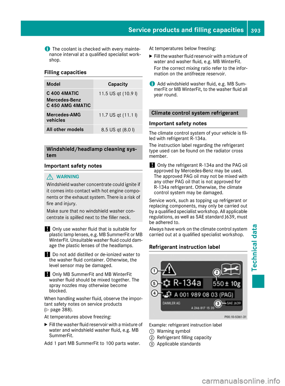
Refrigerant instruction label
Example: refrigerant instruction label
:
Warning symbol
;Refrigerant filling capacity
=Applicable standards
Service products and filling capacities393
Technical data
Z