2016 MERCEDES-BENZ B-Class ELECTRIC Coolant
[x] Cancel search: CoolantPage 9 of 342

Setting the temperature ................ 120
Switching air-recirculation mode
on/off ............................................ 123
Switching on/off ........................... 118
Switching the rear window
defroster on/off ............................ 122
Switching the ZONE function on/
off .................................................. 121
Cockpit
Overview .......................................... 30
COLLISION PREVENTION ASSIST
PLUS
Activating/deactivating ................. 194
Display message ............................ 209
Operation/notes .............................. 63
COMAND
Generated electricity ..................... 144
COMAND display
Cleaning ......................................... 278
Combination switch .......................... 102
Compass
Calibrating ..................................... 267
Calling up ....................................... 266
Magnetic field zone maps .............. 267
Setting ........................................... 267
Consumption statistics (on-board
computer) .......................................... 187
Convenience closing feature .............. 84
Convenience opening feature ............ 84
Convenience opening/closing (air-
recirculation mode) ........................... 123
Coolant (engine)
Checking the level ......................... 271
Filling capacity ............................... 336
Important safety notes .................. 336
Cooling
see Climate control
Copyright ............................................. 28
Cornering light function
Changing bulbs .............................. 107
Display message ............................ 214
Function/notes ............................. 103
Crash-responsive emergency light-
ing ....................................................... 104
Cruise control
Activation conditions ..................... 162
Cruise control lever ....................... 162 Deactivating ................................... 163
Display message ............................ 222
Driving system ............................... 162
Function/notes ............................. 162
Important safety notes .................. 162
Setting a speed .............................. 163
Storing and maintaining current
speed ............................................. 162
Cup holder
Center console .............................. 252
Important safety notes .................. 251
Rear compartment ......................... 252
Customer Assistance Cente r
( CAC) ..................................................... 26
Customer Relations Department ....... 26
D
Data
see Technical data
Daytime running lamps
Display message ............................ 216
Function/notes ............................. 100
Switching on/off (on-board com-
puter) ............................................. 198
Declarations of conformity ................. 25
Departure time
Setting (on-board computer) .......... 195
Diagnostics connection ...................... 25
Digital speedometer ......................... 189
DIRECT SELECT lever
Transmission ................................. 134
Display
High-voltage battery charge level
(instrument cluster) ....................... 184
Display messages
ASSYST PLUS ................................ 272
Calling up (on-board computer) ..... 200
Drive system .................................. 218
Driving systems ............................. 220
General notes ................................ 200
Hiding (on-board computer) ........... 200
Lights ............................................. 214
Safety systems .............................. 201
SmartKey ....................................... 228
Tires ............................................... 223
Vehicle ........................................... 225
Index7
Page 16 of 342

Recharging statistics (COMAND)see Electrical energy generated
Recuperative Brake System
Driving safety systems ..................... 68
Refrigerant (air-conditioning sys-
tem)
Important safety notes .................. 337
Remote control
Garage door opener ....................... 263
Programming (garage door
opener) .......................................... 264
Replacing bulbs
Important safety notes .................. 104
Overview of bulb types .................. 105
Removing/replacing the cover
(front wheel arch) .......................... 106
Reporting safety defects .................... 26
Rescue card ......................................... 27
Reserve
High-voltage battery ...................... 238
Restraint system
Display message ............................ 210
Introduction ..................................... 40
Warning lamp ................................. 238
Warning lamp (function) ................... 41
Reverse gear
Engaging ........................................ 135
Reversing feature
Side windows ................................... 83
Roadside Assistance (breakdown) .... 22
Roof carrier ........................................ 251
Roof lining and carpets (cleaning
guidelines) ......................................... 280
Roof load (maximum) ........................ 338
S
Safety
Children in the vehicle ..................... 56
Safety system
see Driving safety systems
Seat belts
Adjusting the height ......................... 44
center rear-compartment seat ......... 45
Cleaning ......................................... 279
Correct usage .................................. 44
Fastening ......................................... 44
Important safety guidelines ............. 42 Introduction ..................................... 42
Releasing ......................................... 45
Warning lamp ................................. 229
Warning lamp (function) ................... 45
Seats
Adjusting (electrically) ..................... 91
Adjusting (manually) ........................ 90
Adjusting the 4-way lumbar sup-
port .................................................. 92
Adjusting the head restraint ............ 91
Cleaning the cover ......................... 279
Correct driver's seat position ........... 88
Folding the backrest (rear com-
partment) forwards/back .............. 246
Important safety notes .................... 89
Seat heating problem ...................... 94
Storing settings (memory func-
tion) ................................................. 98
Switching seat heating on/off ......... 92
Securing a load
see Securing cargo
Securing cargo .................................. 247
Selector lever
Cleaning ......................................... 278
see DIRECT SELECT lever
Sensors (cleaning instructions) ....... 277
Service menu (on-board com-
puter) .................................................. 194
Service message
see ASSYST PLUS
Service products
Brake fluid ..................................... 335
Coolant (engine) ............................ 336
Important safety notes .................. 335
Refrigerant (air-conditioning sys-
tem) ............................................... 337
Washer fluid ................................... 336
Setting the air distribution ............... 120
Setting the airflow ............................ 121
Setting the maximum charge cur-
rent (Control system) ........................ 196
Settings
Factory (on-board computer) ......... 198
On-board computer ....................... 195
Side impact air bag ............................. 48
Si de marker lamp (display mes-
sage) ................................................... 216
14Index
Page 26 of 342

the vehicle's high-voltage electrical system
checked by a qualified specialist workshop.
All of the vehicle's high-voltage electrical sys-
tem components are marked with yellow
warning stickers which warn you about high
voltages. The cables of the vehicle's high-
voltage electrical system are orange.
When towing a vehicle after an accident, be
sure to observe the following sections:
RTransporting the vehicle (Ypage 297)
RTowing the vehicle with the front axle raised
(
Ypage 297)
RTowing a vehicle with both axles on the
ground (
Ypage 296)
Read the important safety instructions on
towing away (
Ypage 294).
The ignition must be switched off when car-
rying out general tasks, such as changing
bulbs or checking the coolant level.
Automatic switching off of the vehicle's high-voltage electrical system
If the restraint systems are activated during
an accident, the vehicle's high-voltage elec-
trical system is automatically deactivated.
This is to ensure that you do not come into
contact with high voltage.
Automatic protection from switching
on of the vehicle's high-voltage electri-
cal system
The vehicle's high-voltage electrical system is
not activated when the vehicle is started if:
Ra serious electrical insulation malfunction
is detected in the vehicle's high-voltage
electrical system.
Ran electrical connection in the vehicle's
high-voltage electrical system is discon-
nected.
Automatic switching off of the charging
process
The charging process is deactivated automat-
ically if:
Rthe high-voltage battery is fully charged
The charging process is interrupted automat-
ically if:
Ra serious electrical insulation malfunction
is detected in the vehicle's high-voltage
electrical system.
Ran electrical connection in the vehicle's
high-voltage electrical system is discon-
nected.
High-voltage switch-off device
!The high-voltage system must only be
switched off at vehicle standstill by spe-
cially trained service engineers. Otherwise
the high-voltage system may be damaged.
Your vehicle is equipped with a high-voltage
switch-off device :which can be used to
24Introduction
Page 220 of 342

Drive system
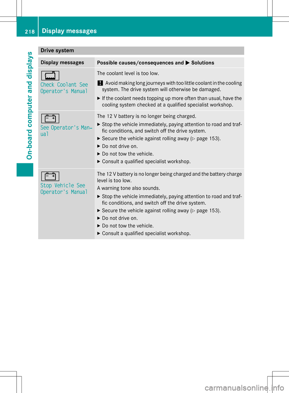
Display messagesPossible causes/consequences andMSolutions
+
Check Coolant See
Operator's Manual
The coolant level is too low.
!Avoid making long journeys withtoo little coolant in the cooling
system. The drive system will otherwise be damaged.
XIf th e coolant needs topping up more often than usual, have the
cooling system checked at a qualified specialist workshop.
#
SeeOperator'sMan‐
ual
The 12 V battery is no longer being charged.
XStop th e vehicle immediately, paying attention to road and traf-
fic conditions, and switch off the drive system.
XSecur eth e vehicle against rolling away (Ypage 153).
XDo no t drive on.
XDo notto w the vehicle.
XConsult a qualified specialist workshop.
#
Stop Vehicle See
Operator's Manual
The 12 V battery is no longer being charged and the battery charge
level is too low.
A warning tone also sounds.
XStop th e vehicle immediately, paying attention to road and traf-
fic conditions, and switch off the drive system.
XSecur eth e vehicle against rolling away (Ypage 153).
XDo no t drive on.
XDo notto w the vehicle.
XConsult a qualified specialist workshop.
218Display messages
On-board computer and displays
Page 273 of 342

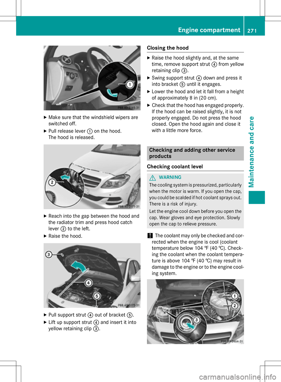
XMake sure that the windshield wipers are
switched off.
XPull release lever:on the hood.
The hood is released.
XReach into the gap between the hood and
the radiator trim and press hood catch
lever ;to the left.
XRaise the hood.
XPull support strut ?out of bracket A.
XLift up support strut ?and insert it into
yellow retaining clip =.
Closing the hood
XRaise the hood slightly and, at the same
time, remove support strut ?from yellow
retaining clip =.
XSwing support strut ?down and press it
into bracket Auntil it engages.
XLower the hood and let it fall from a height
of approximately 8 in (20 cm).
XCheck that the hood has engaged properly.
If the hood can be raised slightly, it is not
properly engaged. Do not press the hood
closed. Open the hood again and close it
with a little more force.
Checking and adding other service
products
Checking coolant level
GWARNING
The cooling system is pressurized, particularly
when the motor is warm. If you open the cap,
you could be scalded if hot coolant sprays out.
There is a risk of injury.
Let the engine cool down before you open the
cap. Wear gloves and eye protection. Slowly
open the cap to relieve pressure.
!The coolant may only be checked and cor-
rected when the engine is cool (coolant
temperature below 104 ‡ (40 †). Check-
ing the coolant when the coolant tempera-
ture is above 104 ‡ (40 †) may result in
damage to the engine or to the engine cool-
ing system.
Engine compartment271
Maintenance and care
Z
Page 274 of 342

XPark the vehicle on a level surface.
Only check the coolant level when the vehi-
cle is on a level surface and the drive sys-
tem has cooled down.
XTurn the SmartKey to position2in the igni-
tion lock (
Ypage 131).
XCheck the coolant temperature display in
the instrument cluster.
The coolant temperature must be below
104 ‡ (40 †).
XTurn the SmartKey to position 0in the igni-
tion lock (
Ypage 131).
XSlowly turn cap :counter-clockwise to
relieve excess pressure.
XTurn cap :further counter-clockwise and
remove it.
If the coolant is at the level of marker bar =
in the filler neck when cold, there is enough
coolant in coolant expansion tank ;.
XIf necessary, add coolant that has been tes-
ted and approved by Mercedes-Benz.
XReplace cap:and turn it clockwise as far
as it will go.
For further information on coolant, see
(
Ypage 336).
Windshield washer system
GWARNING
Certain components in the engine compart-
ment may be very hot, e.g. the drive system
and radiator. Working in the engine compart-
ment poses a risk of injury.
If possible, let the drive system cool down and only touch the components described in the
following.
GWARNING
Windshield washer concentrate is highly flam- mable. If it comes into contact with hot com-
ponents in the front compartment, it may
ignite. There is a risk of fire and injury.
Make sure that no windshield washer con-
centrate is spilled next to the filler neck.
XTo open: pull cap:upwards by the tab.
XAdd the premixed washer fluid.
XTo close: press cap :onto the filler neck
until it engages.
If the washer fluid level drops below the rec-
ommended minimum of 1 liter, a message
appears in the multifunction display prompt-
ing you to add washer fluid (
Ypage 227).
Further information on windshield washer
fluid/antifreeze (
Ypage 336).
ASSYST PLUS
Service message
The ASSYST PLUS service interval display
informs you of the next service due date.
You can find information on the type of ser-
vice and service intervals in the Maintenance
Booklet.
You can obtain further information from an
authorized Mercedes-Benz Center or at
http://www.mbusa.com (USA only).
The multifunction display shows a service
message for several seconds, e.g.:
RService A in .. Days
RService A Due
RService A Exceeded by .. Days
Depending on the operating conditions of the
vehicle, the remaining time or distance until
the next service due date is displayed.
The letter A
orB, possibly in connection with a
number or another letter, indicates the type
272ASSYST PLUS
Maintenance and care
Page 277 of 342

XRinse the vehicle with clean water and dry
thoroughly withachamois.
XDo not let the cleaning agent dry on the
paintwork.
Carefully remove all deposits of road salt as
soon as possible when driving in winter.
Power washers
GWARNING
The water jet froma circular jet nozzle (dirt
blasters) can cause invisible exterior damage
to th e tires or chassis components. Compo-
nent s damaged in this way may fail unexpect-
edly. There is a risk of an accident.
Do no t use power washers with circular jet
nozzles to clean th e vehicle. Have damaged
tires or chassis components replaced imme-
diately.
!Always maintainadistance of at least
11.8 in (30 cm)betwee n thevehicl e and the
power washer nozzle. Information about
the correct distance is available from the
equipment manufacturer.
Move the power washer nozzle around
when cleaning your vehicle.
Do not aim directly at any of the following:
Rtires
Rdoor gaps, roof gaps, joints, etc.
Relectrical components
Rbattery
Rconnectors
Rlights
Rseals
Rtrim
Rventilation slots
Damaged seals or electrical components
can lead to leaks or failures.
Cleaning the paintwork
!Do not affix:
Rstickers
Rfilms
Rmagnetic plates or similar items
to painted surfaces. You could otherwise
damage the paintwork.
Scratches, corrosive deposits, areas affected
by corrosion and damage caused by inade-
quate care cannot always be completely
repaired. In such cases, visit a qualified spe-
cialist workshop.
XRemove dirt immediately, where possible,
while avoiding rubbing too hard.
XSoak insect remains with insect remover
and rinse off the treated areas afterwards.
XSoak bird droppings with water and rinse
off the treated areas afterwards.
XRemove coolant, brake fluid, tree resin,
oils, fuels and greases by rubbing gently
with a cloth soaked in petroleum ether or
lighter fluid.
XUse tar remover to remove tar stains.
XUse silicone remover to remove wax.
If water no longer forms "beads" on the paint surface, use the paint care products recom-
mended and approved by Mercedes-Benz.
This is the case approximately every three to
five months, depending on the climate con-
ditions and the care product used.
If dirt has penetrated the paint surface or if
the paint has become dull, the paint cleaner
recommended and approved by Mercedes-
Benz should be used.
Do not use these care products in the sun or
on the hood while the hood is hot.
XUse a suitable touch-up stick, e.g. MB
Touch-Up Stick, to repair slight damage to
the paintwork quickly and provisionally.
Care275
Maintenance and care
Z
Page 324 of 342

Curb weight
The weight of a vehicle with standard equip-
ment including the maximum capacity of fuel,
oil and coolant. It also includes the air-condi-
tioning system and optional equipment if
these are installed in the vehicle, but does not
include passengers or luggage.
Maximum load rating
The maximum tire load is the maximum per-
missible weight in kilograms or lbs for which a
tire is approved.
Maximum permissible tire pressure
Maximum permissible tire pressure for one
tire.
Maximum load on one tire
Maximum load on one tire. This is calculated
by dividing the maximum axle load of one axle
by two.
PSI (pounds per square inch)
A standard unit of measure for tire pressure.
Aspect ratio
Relationship between tire height and tire
width in percent.
Tire pressure
This is pressure inside the tire applying an
outward force to each square inch of the tire's
surface. The tire pressure is specified in
pounds per square inch (psi), in kilopascal
(kPa) or in bar. The tire pressure should only
be corrected when the tires are cold.
Cold tire pressure
The tires are cold:
Rif the vehicle has been parked with the tires
out of direct sunlight for at least three
hours and
Rif the vehicle has not been driven further
than 1 mile (1.6 km) Tread
The part of the tire that comes into contact
with the road.
Bead
The tire bead ensures that the tire sits
securely on the wheel. There are several steel
wires in the bead to prevent the tire from
coming loose from the wheel rim.
Sidewall
The part of the tire between the tread and the
bead.
Weight of optional extras
The combined weight of those optional extras
that weigh more than the replaced standard
parts and more than 2.3 kg (5 lbs). These
optional extras, such as high-performance
brakes, level control, a roof rack or a high-
performance battery, are not included in the
curb weight and the weight of the accesso-
ries.
TIN (Tire Identification Number)
This is a unique identifier which can be used
by a tire manufacturer to identify tires, for
example for a product recall, and thus identify
the purchasers. The TIN is made up of the
manufacturer's identity code, tire size, tire
type code and the manufacturing date.
Load bearing index
The load bearing index (also load index) is a
code that contains the maximum load bearing
capacity of a tire.
Traction
Traction is the result of friction between the
tires and the road surface.
Treadwear indicators
Narrow bars (tread wear bars) that are dis-
tributed over the tire tread. If the tire tread is
level with the bars, the wear limit of áin
(1.6 mm) has been reached.
322All about wheels and tires
Wheels and tires