2016 Lexus GS450h brake
[x] Cancel search: brakePage 448 of 544
448
GS450h_OM_OM30E99U_(U)
7-2. Steps to take in an emergency
If the shift lever cannot be shifted from P
Press the parking brake switch to check that the parking brake is set. (P. 1 9 3 )
Parking brake indicator will come on.
Turn the power switch to ACCESSORY mode.
Depress the brake pedal.
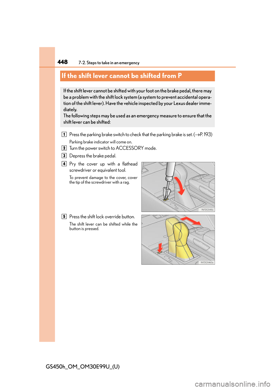
Pry the cover up with a flathead
screwdriver or equivalent tool.
To prevent damage to the cover, cover
the tip of the screwdriver with a rag.
Press the shift lock override button.
The shift lever can be shifted while the
button is pressed.
If the shift lever cannot be shifted with your foot on the brake pedal, there may
be a problem with the shift lock system (a system to prevent accidental opera-
tion of the shift lever). Have the vehicl e inspected by your Lexus dealer imme-
diately.
The following steps may be used as an emergency measure to ensure that the
shift lever can be shifted:
1
2
3
4
5
Page 449 of 544
449
GS450h_OM_OM30E99U_(U)
7
When trouble arises
7-2. Steps to take in an emergency
If the parking brake cannot be released
●Shift the shift lever to P.
●Turn the power switch off.
●Check that the parking brake indicator is off.
●Chock the tires.
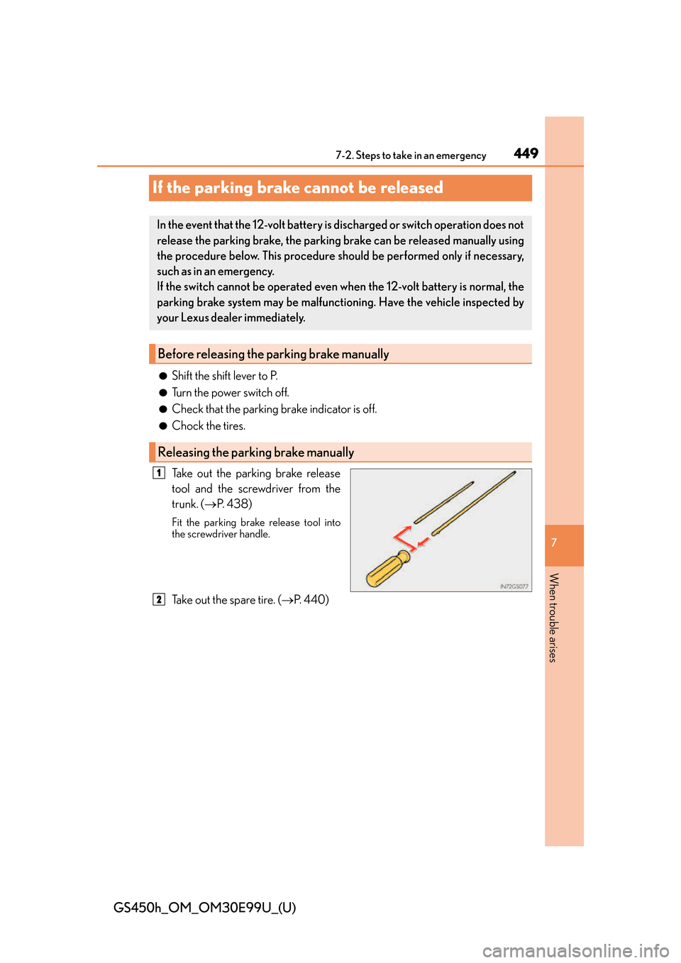
Take out the parking brake release
tool and the screwdriver from the
trunk. ( P. 4 3 8 )
Fit the parking brake release tool into
the screwdriver handle.
Take out the spare tire. ( P. 4 4 0 )
In the event that the 12-volt battery is discharged or switch operation does not
release the parking brake, the parking brake can be released manually using
the procedure below. This procedure should be performed only if necessary,
such as in an emergency.
If the switch cannot be operated even when the 12-volt battery is normal, the
parking brake system may be malfunctioning. Have the vehicle inspected by
your Lexus dealer immediately.
Before releasing the parking brake manually
Releasing the parking brake manually
1
2
Page 450 of 544
4507-2. Steps to take in an emergency
GS450h_OM_OM30E99U_(U)
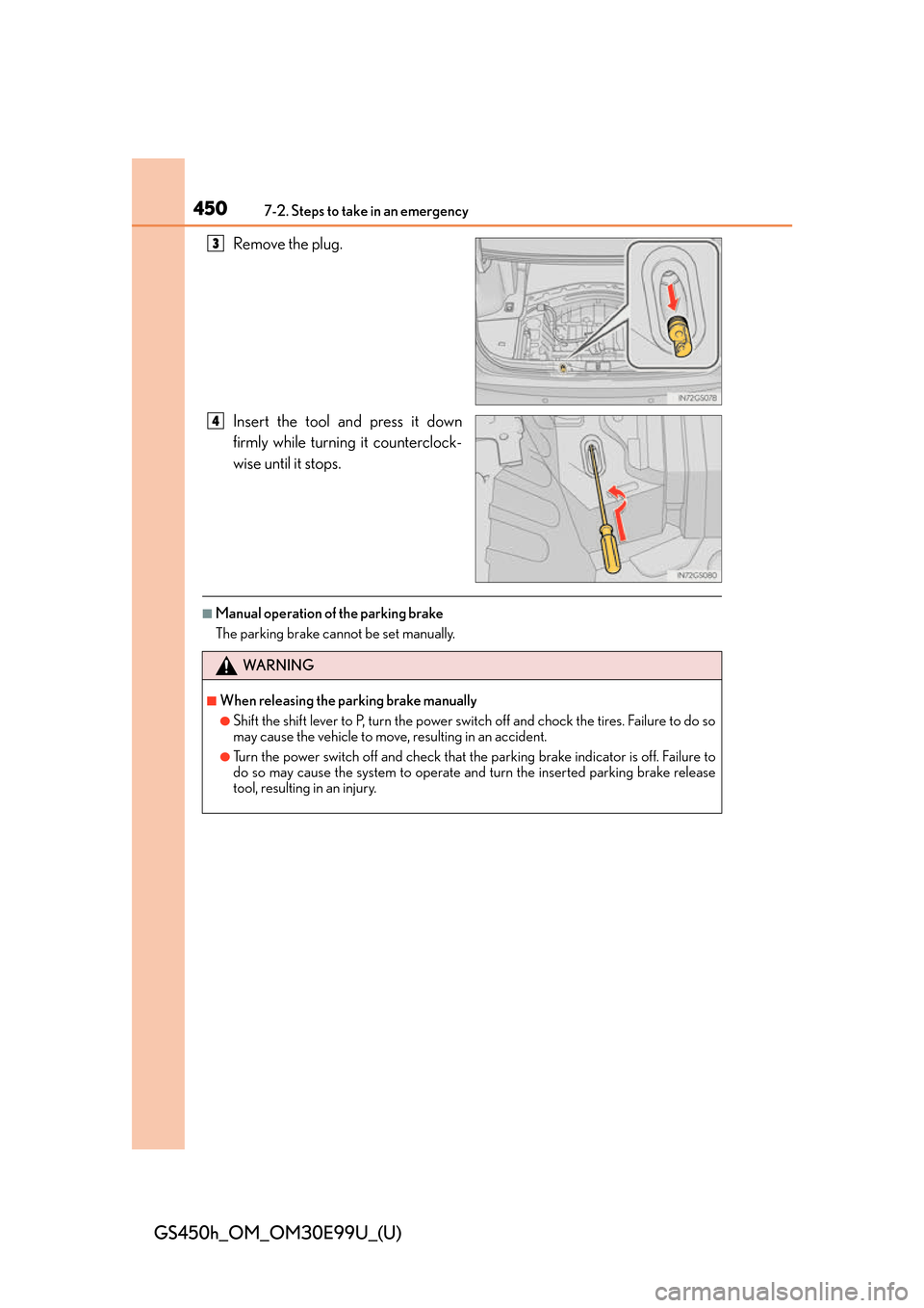
Remove the plug.
Insert the tool and press it down
firmly while turning it counterclock-
wise until it stops.
■Manual operation of the parking brake
The parking brake cannot be set manually.
3
4
WA R N I N G
■When releasing the parking brake manually
●Shift the shift lever to P, turn the power switch off and chock the tires. Failure to do so
may cause the vehicle to move, resulting in an accident.
●Turn the power switch off and check that the parking brake indicator is off. Failure to
do so may cause the system to operate and turn the inserted parking brake release
tool, resulting in an injury.
Page 452 of 544
4527-2. Steps to take in an emergency
GS450h_OM_OM30E99U_(U)
Ensure that the shift lever is in P and depress the brake pedal.
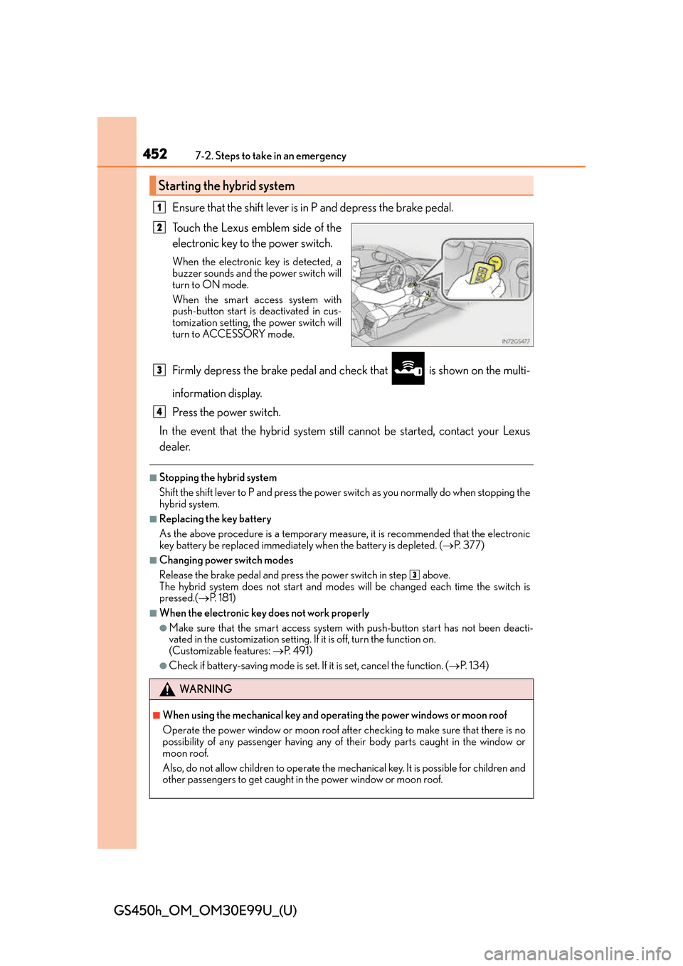
Touch the Lexus emblem side of the
electronic key to the power switch.
When the electronic key is detected, a
buzzer sounds and the power switch will
turn to ON mode.
When the smart access system with
push-button start is deactivated in cus-
tomization setting, the power switch will
turn to ACCESSORY mode.
Firmly depress the brake pedal and check that is shown on the multi-
information display.
Press the power switch.
In the event that the hybrid system still cannot be started, contact your Lexus
dealer.
■Stopping the hybrid system
Shift the shift lever to P and press the power switch as you normally do when stopping the
hybrid system.
■Replacing the key battery
As the above procedure is a temporary measure, it is recommended that the electronic
key battery be replaced immediately when the battery is depleted. ( P. 377)
■Changing power switch modes
Release the brake pedal and press the power switch in step above.
The hybrid system does not start and mode s will be changed each time the switch is
pressed.( P. 181)
■When the electronic key does not work properly
●Make sure that the smart access system wi th push-button start has not been deacti-
vated in the custom ization setting. If it is off, turn the function on.
(Customizable features: P. 4 9 1 )
●Check if battery-saving mo de is set. If it is set, cancel the function. ( P. 1 3 4 )
Starting the hybrid system
1
2
WA R N I N G
■When using the mechanical key and operating the power windows or moon roof
Operate the power window or moon roof afte r checking to make sure that there is no
possibility of any passenger having any of their body parts caught in the window or
moon roof.
Also, do not allow children to operate the mech anical key. It is possible for children and
other passengers to get caught in the power window or moon roof.
3
4
3
Page 462 of 544
462
GS450h_OM_OM30E99U_(U)
7-2. Steps to take in an emergency
If the vehicle becomes stuck
Stop the hybrid system. Set the parking brake and shift the shift lever to P.
Remove the mud, snow or sand from around the rear wheels.
Place wood, stones or some other material under the rear wheels to help pro-
vide traction.
Restart the hybrid system.
Shift the shift lever to D or R and release the parking brake. Then, while exer-
cising caution, depress the accelerator pedal.
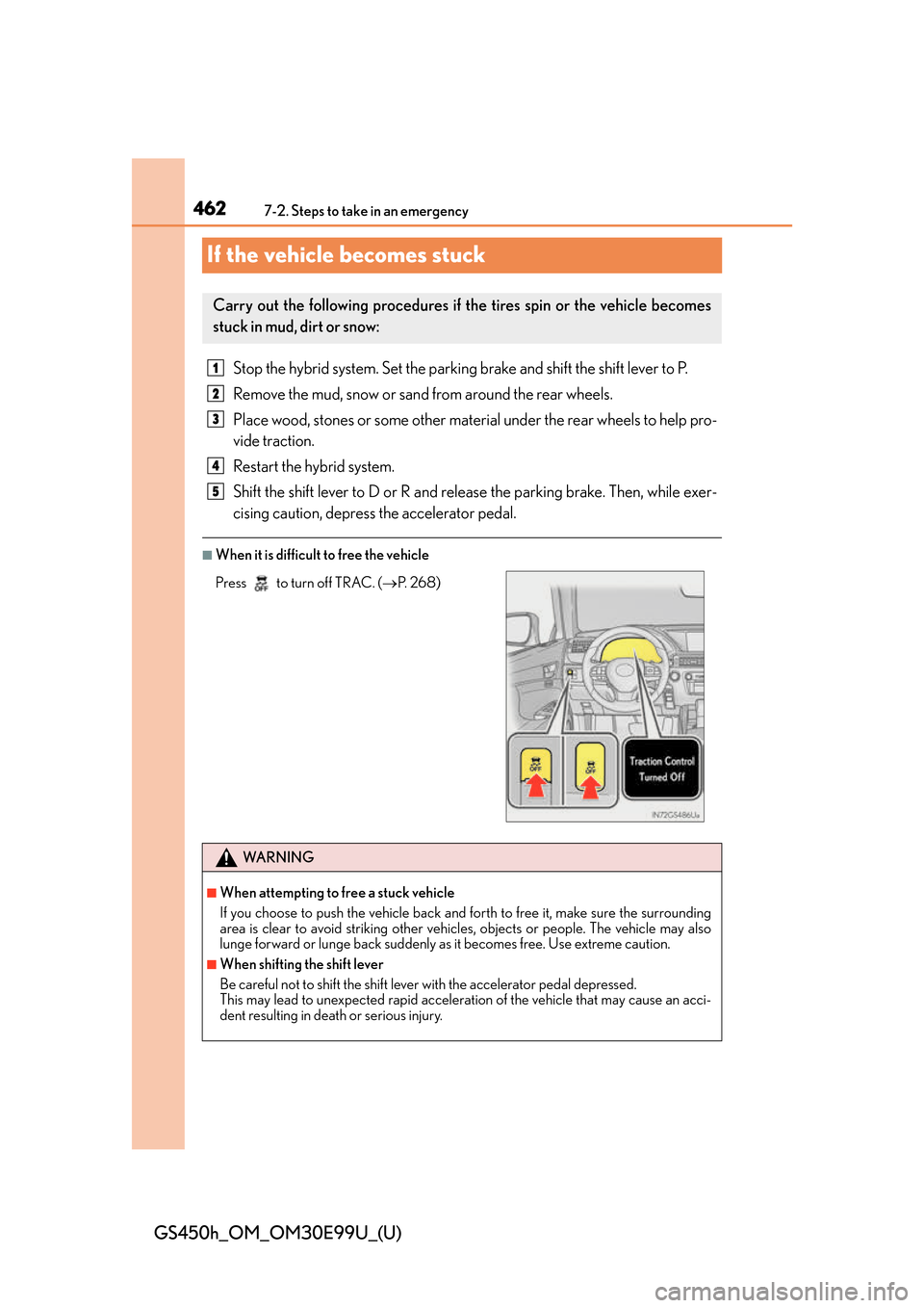
■When it is difficult to free the vehicle
Carry out the following procedures if the tires spin or the vehicle becomes
stuck in mud, dirt or snow:
Press to turn off TRAC. ( P. 2 6 8 )
WA R N I N G
■When attempting to free a stuck vehicle
If you choose to push the vehicle back and forth to free it, make sure the surrounding
area is clear to avoid striking other vehicl es, objects or people. The vehicle may also
lunge forward or lunge back suddenly as it becomes free. Use extreme caution.
■When shifting the shift lever
Be careful not to shift the shift lever with the accelerator pedal depressed.
This may lead to unexpected rapid accelerati on of the vehicle that may cause an acci-
dent resulting in death or serious injury.
1
2
3
4
5
Page 473 of 544
GS450h_OM_OM30E99U_(U)
4738-1. Specifications
8
Vehicle specifications
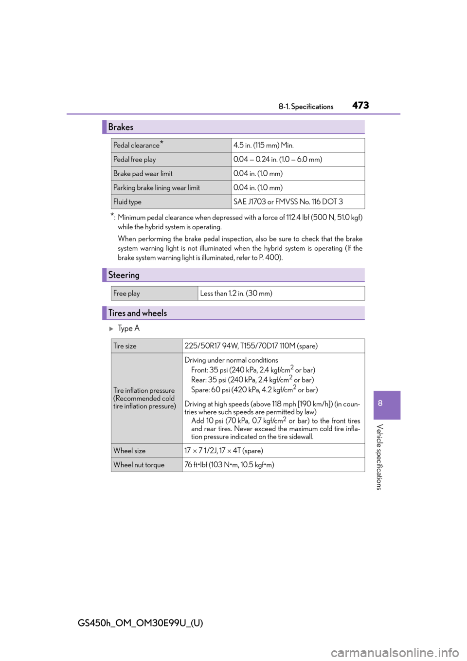
*: Minimum pedal clearance when depressed with a force of 112.4 lbf (500 N, 51.0 kgf)
while the hybrid system is operating.
When performing the brake pedal inspection, also be sure to check that the brake
system warning light is not illuminated when the hybrid system is operating (If the
brake system warning light is illuminated, refer to P. 400).
Ty p e A
Brakes
Pe d a l c l e a r a n c e*4.5 in. (115 mm) Min.
Pedal free play0.04 — 0.24 in. (1.0 — 6.0 mm)
Brake pad wear limit0.04 in. (1.0 mm)
Parking brake lining wear limit0.04 in. (1.0 mm)
Fluid typeSAE J1703 or FMVSS No. 116 DOT 3
Steering
Free playLess than 1.2 in. (30 mm)
Tires and wheels
Ti r e s i z e225/50R17 94W, T155/70D17 110M (spare)
Tire inflation pressure
(Recommended cold
tire inflation pressure)
Driving under normal conditions
Front: 35 psi (240 kPa, 2.4 kgf/cm2 or bar)
Rear: 35 psi (240 kPa, 2.4 kgf/cm2 or bar)
Spare: 60 psi (420 kPa, 4.2 kgf/cm2 or bar)
Driving at high speeds (above 118 mph [190 km/h]) (in coun-
tries where such speeds are permitted by law) Add 10 psi (70 kPa, 0.7 kgf/cm
2 or bar) to the front tires
and rear tires. Never exceed the maximum cold tire infla-
tion pressure indicated on the tire sidewall.
Wheel size17 7 1 /2J, 17 4T (spare)
Wheel nut torque76 ft•lbf (103 N•m, 10.5 kgf•m)
Page 486 of 544
486
GS450h_OM_OM30E99U_(U)
8-1. Specifications
■Temperature A, B, C
The temperature grades are A (the highest), B, and C, representing the tire’s
resistance to the generation of heat and its ability to dissipate heat when
tested under controlled conditions on a specified indoor laboratory test
wheel.
Sustained high temperature can cause the material of the tire to degenerate and
reduce tire life, and excessive temperature can lead to sudden tire failure.
Grade C corresponds to a level of perfor mance which all passenger car tires must
meet under the Federal Motor Vehicle Safety Standard No. 109.
Grades B and A represent higher levels of performance on the laboratory test
wheel than the minimum required by law.
Warning: The temperature grades of a tire assume that it is properly inflated and
not overloaded.
Excessive speed, underinflation, or excessiv e loading, either separately or in com-
bination, can cause heat buildup and possible tire failure.
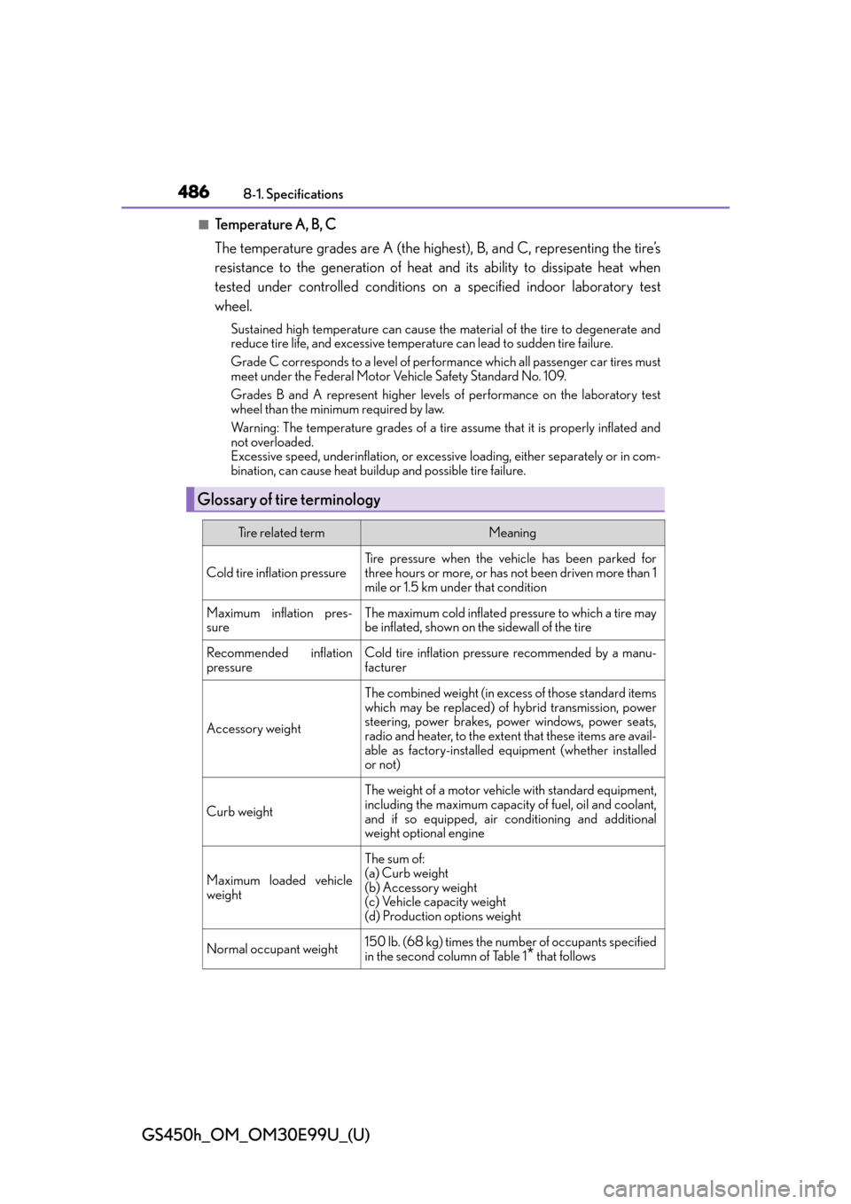
Glossary of tire terminology
Tire related termMeaning
Cold tire inflation pressure
Tire pressure when the vehicle has been parked for
three hours or more, or has not been driven more than 1
mile or 1.5 km un der that condition
Maximum inflation pres-
sureThe maximum cold inflated pressure to which a tire may
be inflated, shown on the sidewall of the tire
Recommended inflation
pressureCold tire inflation pressure recommended by a manu-
facturer
Accessory weight
The combined weight (in excess of those standard items
which may be replaced) of hybrid transmission, power
steering, power brakes, power windows, power seats,
radio and heater, to the extent that these items are avail-
able as factory-installed eq uipment (whether installed
or not)
Curb weight
The weight of a motor vehicle with standard equipment,
including the maximum capacity of fuel, oil and coolant,
and if so equipped, air co nditioning and additional
weight optional engine
Maximum loaded vehicle
weight
The sum of:
(a) Curb weight
(b) Accessory weight
(c) Vehicle capacity weight
(d) Production options weight
Normal occupant weight150 lb. (68 kg) times the numb er of occupants specified
in the second column of Table 1
* that follows
Page 487 of 544
GS450h_OM_OM30E99U_(U)
4878-1. Specifications
8
Vehicle specifications
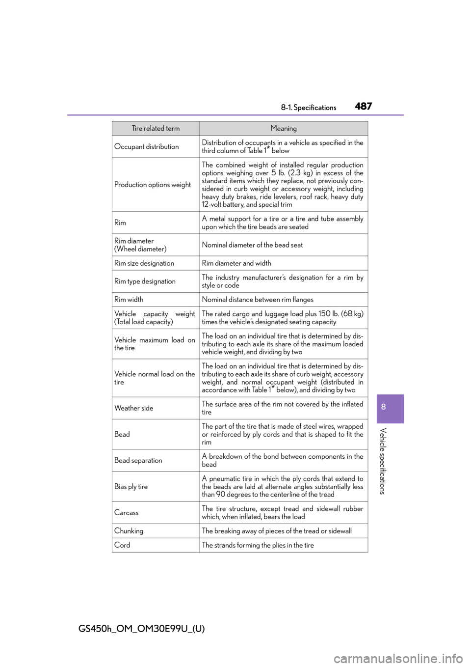
Occupant distributionDistribution of occupants in a vehicle as specified in the
third column of Table 1* below
Production options weight
The combined weight of installed regular production
options weighing over 5 lb. (2.3 kg) in excess of the
standard items which they replace, not previously con-
sidered in curb weight or accessory weight, including
heavy duty brakes, ride levelers, roof rack, heavy duty
12-volt battery, and special trim
RimA metal support for a tire or a tire and tube assembly
upon which the tire beads are seated
Rim diameter
(Wheel diameter)Nominal diameter of the bead seat
Rim size designationRim diameter and width
Rim type designationThe industry manufacturer’s designation for a rim by
style or code
Rim widthNominal distance between rim flanges
Vehicle capacity weight
(Total load capacity)The rated cargo and luggage load plus 150 lb. (68 kg)
times the vehicle’s designated seating capacity
Vehicle maximum load on
the tireThe load on an individual tire that is determined by dis-
tributing to each axle its share of the maximum loaded
vehicle weight, and dividing by two
Vehicle normal load on the
tireThe load on an individual tire that is determined by dis-
tributing to each axle its sh are of curb weight, accessory
weight, and normal occupant weight (distributed in
accordance with Table 1
* below), and dividing by two
We a t h e r s i d eThe surface area of the rim not covered by the inflated
tire
Bead
The part of the tire that is made of steel wires, wrapped
or reinforced by ply cords and that is shaped to fit the
rim
Bead separationA breakdown of the bond be tween components in the
bead
Bias ply tireA pneumatic tire in which the ply cords that extend to
the beads are laid at altern ate angles substantially less
than 90 degrees to the centerline of the tread
CarcassThe tire structure, except tread and sidewall rubber
which, when inflated, bears the load
ChunkingThe breaking away of pieces of the tread or sidewall
CordThe strands forming th e plies in the tire
Tire related termMeaning