Page 411 of 524

737
Maintenance
Wheel alignment and tire bal-
ance
The wheels on your vehicle were
aligned and balanced carefully at the
factory to give you the longest tire life
and best overall performance.
In most cases, you will not need to
have your wheels aligned again.
However, if you notice unusual tire
wear or your vehicle pulling one way
or the other, the alignment may need
to be reset.
If you notice your vehicle vibrating
when driving on a smooth road, your
wheels may need to be rebalanced.
Tire replacement
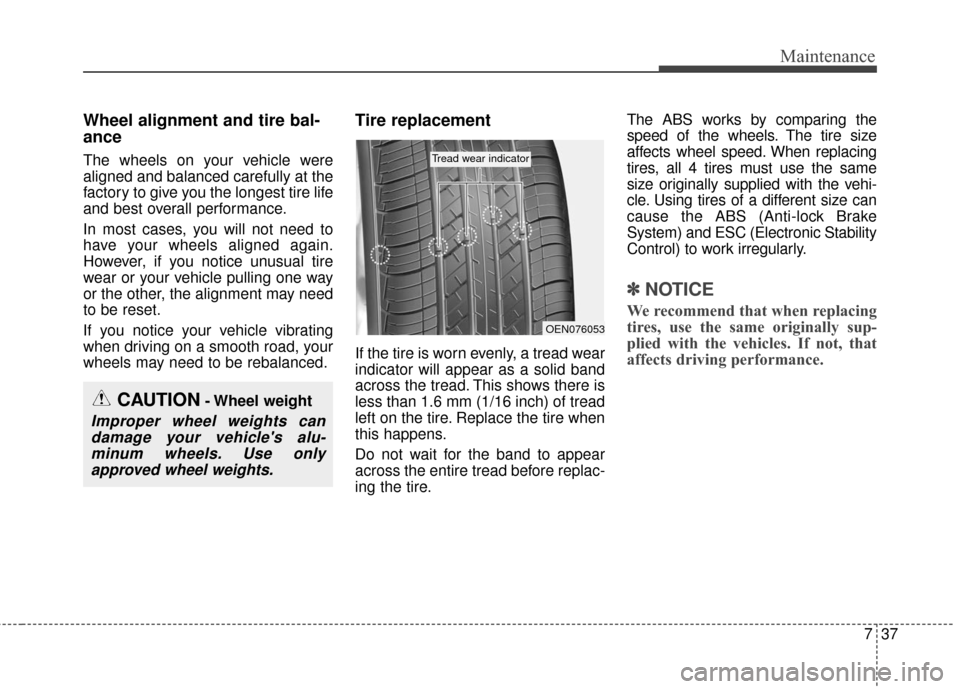
If the tire is worn evenly, a tread wear
indicator will appear as a solid band
across the tread. This shows there is
less than 1.6 mm (1/16 inch) of tread
left on the tire. Replace the tire when
this happens.
Do not wait for the band to appear
across the entire tread before replac-
ing the tire.The ABS works by comparing the
speed of the wheels. The tire size
affects wheel speed. When replacing
tires, all 4 tires must use the same
size originally supplied with the vehi-
cle. Using tires of a different size can
cause the ABS (Anti-lock Brake
System) and ESC (Electronic Stability
Control) to work irregularly.
✽ ✽
NOTICE
We recommend that when replacing
tires, use the same originally sup-
plied with the vehicles. If not, that
affects driving performance.
CAUTION- Wheel weight
Improper wheel weights can
damage your vehicle's alu-minum wheels. Use onlyapproved wheel weights.
OEN076053
Tread wear indicator
Page 437 of 524

763
Maintenance
Front side marker
Follow the steps 1 to 6 from the pre-
vious page.
7.Remove the socket from theassembly by turning the socket
counterclockwise until the tabs on
the socket align with the slots on
the assembly.
8.Pull the bulb out of the socket.
9.Insert a new bulb into the socket.
10. Install the socket into the assem- bly by aligning the tabs on the
socket with the slots on the
assembly and turning the socket
clockwise.
Front fog lamp bulbs (if equipped)
1. Remove the front bumper undercover.
2. Reach your hand into the back of the front bumper. 3. Disconnect the power connector
from the socket.
4. Remove the bulb-socket from the housing by turning the socket
counter clockwise until the tabs on
the socket align with the slots on
the housing.
5. Install the new bulb-socket into the housing by aligning the tabs on
the socket with the slots in the
housing. Push the socket into the
housing and turn the socket clock-
wise.
6. Connect the power connector to the socket.
7. Reinstall the front bumper under cover.
✽ ✽NOTICE
If the headlight aiming adjustment
is necessary after the headlight
assembly is reinstalled, consult an
authorized Kia dealer.
OPS073028
OPSE074029L
OPS073025
Page 439 of 524

765
Maintenance
Turn signal light
4. Remove the socket from theassembly by turning the socket
counterclockwise until the tabs on
the socket align with the slots on
the assembly.
5. Remove the bulb from the socket by pressing it in and rotating it
counterclockwise until the tabs on
the bulb align with the slots in the
socket. 6. Insert a new bulb by inserting it
into the socket and rotating it until
it locks into place.
7. Install the socket in the assembly by aligning the tabs on the socket
with the slots in the assembly and
turning the socket clockwise.
8. Reinstall the light assembly to the body of the vehicle.
Back-up light
Follow the steps 1 to 3 from the pre-
vious page.
4. Remove the socket from theassembly by turning the socket
counterclockwise until the tabs on
the socket align with the slots on
the assembly.
5. Pull the bulb out of the socket.
6. Insert a new bulb into the socket.
7. Install the socket into the assembly by aligning the tabs on the socket
with the slots on the assembly and
turning the socket clockwise.
8. Reinstall the light assembly to the body of the vehicle.
OPS073034OPS073045
Back-up
Page 441 of 524
767
Maintenance
License plate light bulb
replacement
1. Remove the lens by pressing thetabs.
2. Remove the socket from the lens.
3. Remove the bulb by turning it counter clockwise.
4. Install a new bulb in the socket and install the socket to the lens.
5. Reinstall the lens securely.
OPS073050
Map lamp
Room lamp
Glove box lamp
Luggage lamp
Vanity mirror lamp
OPS073041/OPS073042/OPS073043/ OPS073044/OXM079041
Page 442 of 524
Maintenance
68
7
Interior light bulb replacement
1. Using a flat-blade screwdriver,
gently pry the lens from the interi-
or light housing.
2. Remove the bulb by pulling it straight out.
3. Install a new bulb in the socket.
4. Align the lens tabs with the interior light housing notches and snap
the lens into place.
WARNING- Interior lights
Prior to working on the Interior
Lights, ensure that the “OFF”
button is depressed to avoid
burning your fingers or receiv-
ing an electric shock.
CAUTION
Be careful not to dirty or dam- age the lens, lens tab, and plas-tic housings.
Page 460 of 524

I3
Index
Checking the brake fluid level . . . . . . . . . . . . . . . . . 7-23
Brake system. . . . . . . . . . . . . . . . . . . . . . . . . . . . . . . . . 5-16 Anti-lock brake system (ABS) . . . . . . . . . . . . . . . . . 5-22
Electronic parking brake (EPB) . . . . . . . . . . . . . . . . 5-18
Electronic stability control (ESC) . . . . . . . . . . . . . . 5-24
Good braking practices . . . . . . . . . . . . . . . . . . . . . . 5-30
Hill-start assist control (HAC) . . . . . . . . . . . . . . . . . 5-29
Power brakes . . . . . . . . . . . . . . . . . . . . . . . . . . . . . 5-16
Vehicle stability management (VSM) . . . . . . . . . . . 5-28
Bulb wattage . . . . . . . . . . . . . . . . . . . . . . . . . . . . . . . . . . 8-4
Child restraint system . . . . . . . . . . . . . . . . . . . . . . . . . . 3-26 Lower anchor system . . . . . . . . . . . . . . . . . . . . . . . . 3-32
Tether anchor system . . . . . . . . . . . . . . . . . . . . . . . . 3-31
Using a child restraint system . . . . . . . . . . . . . . . . . 3-27
Clean air . . . . . . . . . . . . . . . . . . . . . . . . . . . . . . . . . . . 4-\
113
Climate control air filter . . . . . . . . . . . . . . . . . . . . . . . . 7-25 Filter inspection . . . . . . . . . . . . . . . . . . . . . . . . . . . . 7-25
Filter replacement. . . . . . . . . . . . . . . . . . . . . . . . . . . 7-25
Coolant . . . . . . . . . . . . . . . . . . . . . . . . . . . . . . . . . . . . \
. 7-20 Changing the coolant . . . . . . . . . . . . . . . . . . . . . . . . 7-22
Checking the coolant level . . . . . . . . . . . . . . . . . . . . 7-20
Cruise control system . . . . . . . . . . . . . . . . . . . . . . . . . . 5-32 Cruise control switch . . . . . . . . . . . . . . . . . . . . . . . . 5-33
To cancel cruise control . . . . . . . . . . . . . . . . . . . . . . 5-35
To decrease the cruising speed . . . . . . . . . . . . . . . . . 5-34 To increase cruise control set speed . . . . . . . . . . . . . 5-34
To resume cruising speed at more than approximately
30 km/h (20 mph) . . . . . . . . . . . . . . . . . . . . . . . . . 5-35
To set cruise control speed . . . . . . . . . . . . . . . . . . . . 5-33
To temporarily accelerate with the cruise control on. . 5-34
To turn cruise control off . . . . . . . . . . . . . . . . . . . . . 5-36
Defroster . . . . . . . . . . . . . . . . . . . . . . . . . . . . . . . . . . . . \
4-93 Rear window defroster . . . . . . . . . . . . . . . . . . . . . . . 4-93
Dimensions . . . . . . . . . . . . . . . . . . . . . . . . . . . . . . . . . . . 8-\
2
Door locks . . . . . . . . . . . . . . . . . . . . . . . . . . . . . . . . . . 4-11\
Auto door lock/unlock feature . . . . . . . . . . . . . . . . . 4-13
Child-protector rear door lock . . . . . . . . . . . . . . . . . 4-14
Impact sensing door unlock system . . . . . . . . . . . . . 4-13
Operating door locks from inside the vehicle . . . . . 4-12
Operating door locks from outside the vehicle . . . . 4-11
Speed sensing door lock system . . . . . . . . . . . . . . . 4-13
Economical operation . . . . . . . . . . . . . . . . . . . . . . . . . . 5-37
Emergency starting . . . . . . . . . . . . . . . . . . . . . . . . . . . . . 6-5 Jump starting . . . . . . . . . . . . . . . . . . . . . . . . . . . . . . . 6-6
Push-starting . . . . . . . . . . . . . . . . . . . . . . . . . . . . . . . . 6-7
Explanation of scheduled maintenance items . . . . . . . 7-19
Exterior overview . . . . . . . . . . . . . . . . . . . . . . . . . . . . . . 2-2
C
D
E