2016 KIA PICANTO fuel
[x] Cancel search: fuelPage 399 of 488
721
Maintenance
EXPLANATION OF SCHEDULED MAINTENANCE ITEMS
Engine oil and filter The engine oil and filter should be
changed at the intervals specified in the
maintenance schedule. If the car is being
driven in severe conditions, more fre-quent oil and filter changes are required. Drive belts
Inspect all drive belts for evidence of cuts,
cracks, excessive wear or oil saturation
and replace if necessary. Drive belts
should be checked periodically for proper
tension and adjusted as necessary. Fuel filter A clogged filter can limit the speed at
which the vehicle may be driven, damage
the emission system and cause multiple
issues such as hard starting. If an exces-
sive amount of foreign matter accumu-
lates in the fuel tank, the filter may
require replacement more frequently.
After installing a new filter, run the engine
for several minutes, and check for leaks
at the connections. We recommend that
the fuel filter be replaced by an author-
ized Kia dealer.
Fuel lines, fuel hoses and con- nections
Check the fuel lines, fuel hoses and con-
nections for leakage and damage. We
recommend that the fuel lines, fuel hoses
and connections be replaced by an
authorized Kia dealer.
Vapor hose and fuel filler cap
The vapor hose and fuel filler cap should
be inspected at those intervals specified
in the maintenance schedule. Make sure
that a new vapor hose or fuel filler cap iscorrectly replaced.
Air cleaner filter
A Genuine Kia air cleaner filter is recom- mended when the filter is replaced.
CAUTION
When you are inspecting the belt,
place the ignition
switch in the LOCK/OFF or ACCposition.
Page 422 of 488
Maintenance
44
7
TIRES AND WHEELS
Tire care
For proper maintenance, safety, and
maximum fuel economy, you must
always maintain recommended tire
inflation pressures and stay within
the load limits and weight distribution
recommended for your vehicle. Recommended cold tire inflation pressures All tire pressures (including the
spare) should be checked when the
tires are cold. “Cold Tires” means the
vehicle has not been driven for at
least three hours or driven less than1.6 km (one mile).
Recommended pressures must be
maintained for the best ride, top vehi-
cle handling, and minimum tire wear.
For recommended inflation pressure,
refer to “Tire and wheels” in section 8. All specifications (sizes and pres-
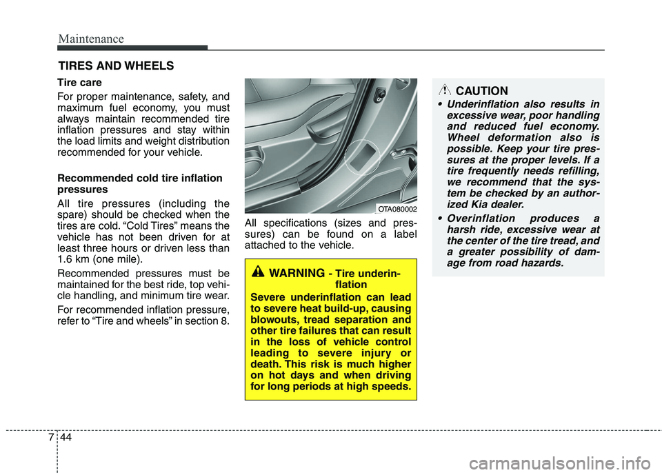
sures) can be found on a label
attached to the vehicle.
WARNING
- Tire underin-
flation
Severe underinflation can lead
to severe heat build-up, causing
blowouts, tread separation andother tire failures that can result
in the loss of vehicle control
leading to severe injury or
death. This risk is much higher
on hot days and when driving
for long periods at high speeds.
OTA080002
CAUTION
Underinflation also results in excessive wear, poor handlingand reduced fuel economy. Wheel deformation also ispossible. Keep your tire pres-sures at the proper levels. If a tire frequently needs refilling,we recommend that the sys-tem be checked by an author- ized Kia dealer.
Overinflation produces a harsh ride, excessive wear atthe center of the tire tread, anda greater possibility of dam- age from road hazards.
Page 443 of 488

765
Maintenance
SymbolFuse ratingProtected Component
MULTI FUSE80AEPS Control Module
125AAlternator, PCB Fuse & Relay Box
FUSE
50AI/P Junction Box (Power Connector Fuse : F1 10A / F2 20A,
Fuse : F24 10A / F25 10A / F26 10A / F27 15A, Tail Lamp Relay)
40AProjection Type : E/R Sub Fuse Box (Fuse : F1 10A / F2 20A / F4 15A / F5 10A / F7 10A )
50AI/P Junction Box (Fuse : F8 20A / F9 25A / F10 15A / F16 15A / F17 25A / F18 15A / F19 10A
/ F35 10A, Power Window Relay)
40AE/R Junction Box (Fuse : F11 15A), Ignition Switch, PDM Relay Box (ESCL Relay)
40AABS Control Relay, ESC Control Relay
30AABS Control Relay, ESC Control Relay
40ARear Defogger Relay
40APCB Fuse & Relay Box (Start Relay), Ignition Switch, PDM Relay Box (ESCL Relay)
30APCB Fuse & Relay Box (Engine Control Relay, Fuse : F23 10A)
40APCB Fuse & Relay Box (Blower Relay)
40APCB Fuse & Relay Box (Cooling Fan Relay)
FUSE
(General head light type)10AInstrument Cluster, Head Lamp RH, PCB Fuse & Relay Box (Head Lamp (HI) Relay)
2FUEL PUMP
(FFV)
VACCUM PUMP (EU K3 AT)
15APCB Fuse & Relay Box (Fuel Pump #2 Relay)
Engine compartment main fuse panel
Page 444 of 488

Maintenance
66
7
SymbolFuse ratingProtected Component
FUSE
(General head light type)
1FUEL
PUMP15APCB Fuse & Relay Box (Fuel Pump #1 Relay)
20APCB Fuse & Relay Box (Head Lamp (HI) Relay)
20APCB Fuse & Relay Box (Head Lamp (LO) Relay)
10APCB Fuse & Relay Box (Horn Relay, Burglar Alarm Horn Relay)
10APCB Fuse & Relay Box (A/C Relay)
10APCM (B3LA)
10ATCM (F3LA/F4LA/F3LA), PCM (B3LA)
10ATransaxle Range Switch, TCM/PCM, ESC Control Module, Rear Bumper Lamp,
Instrument Cluster, BCM, Back-Up Lamp LH/RH, Back-Up Lamp Switch
10AECM/PCM, Front Wiper Motor, Multifunction Switch
20AIgnition coil, condensor
15ATCM/PCM, Injector #1/#2/#3, Injector #4 (G4LA), Jumper Wire 1, Crash Pad Switch (B4LA),
Fuel Pump #2 Relay (B3LA)
10AHead Lamp LH
10A
G3LA/G4LA/F3LA : TCM/ECM, Camshaft Position Sensor #1/#2, Oxygen Sensor (UP)/(DOWN),
Canister Purge Solenoid Valve, Oil Control Valve #1/#2, PCB Fuse & Relay Box (A/C Relay,
Cooling Fan Relay, Start Relay), B3LA : PCM, Camshaft Position Sensor #1/#2,
PCB Fuse & Relay Box (A/C Relay, Cooling Fan Relay), Oxygen Sensor (UP)/(DOWN),
Canister Purge Solenoid Valve, Oil Control Valve #1/#2, Variable Intake Solenoid Valve
10AHead Lamp RH
Page 445 of 488

767
Maintenance
SymbolFuse ratingProtected Component
FUSE
(Projection
head light type)
10APCB Fuse & Relay Box (A/C Relay)
20APCB Fuse & Relay Box (Head Lamp (LO) Relay)
1 FUEL
PUMP15APCB Fuse & Relay Box (Fuel Pump #1 Relay)
10APCB Fuse & Relay Box (Horn Relay, Burglar Alarm Horn Relay)
2 FUEL PUMP
(FFV)
VACCUM PUMP (EU K3 AT)
15AB3LA : PCB Fuse & Relay Box (Fuel Pump #2 Relay)
10APCB Fuse & Relay Box (Head Lamp (HI) Relay)
20AIgnition coil, condensor
15APCB Fuse & Relay Box (Engine Control Relay, Fuel Pump #1 Relay,
Fuel Pump #2 Relay (F3LA)), Injector #1/#2/#3 (B3LA), PCM
10AB3LA : PCM, PCB Fuse & Relay Box (Engine Control Relay)
10ATCM, Transaxle Range Switch, Rear Bumper Lamp, Instrument Cluster, BCM,
Back-Up Lamp LH/RH, Back-Up Lamp Switch
10AECM, Front Wiper Motor, Multifunction Switch
10AProjection Lamp LH
10AECM/TCM/PCM, PCB Fuse & Relay Box (Engine Control Relay)
10AProjection Lamp RH
10A
PCB Fuse & Relay Box (Engine Control Relay, A/C Relay, A/C Relay, Cooling Fan Relay,
Start Relay), ECM/PCM, Canister Purge Control Valve, Oil Control Valve #1,
Oil Control Valve #2 (W/O F3LA), Camshaft Position Sensor #1,
Camshaft Position Sensor #2 (W/O F3LA), Variable Intake Solenoid Valve (B3LA)
Page 456 of 488
Maintenance
78
7
Finish damage repair
Deep scratches or stone chips in the
painted surface must be repaired
promptly. Exposed metal will quickly rust
and may develop into a major repair
expense.
✽✽
NOTICE
If your vehicle is damaged and requires
any metal repair or replacement, be sure
the body shop applies anti-corrosion
materials to the parts repaired or
replaced.
Bright-metal maintenance
To remove road tar and insects, use a tar remover, not a scraper or other
sharp object.
To protect the surfaces of bright-metal parts from corrosion, apply a coating of
wax or chrome preservative and rub to
a high luster.
During winter weather or in coastal areas, cover the bright metal parts with
a heavier coating of wax or preserva-
tive. If necessary, coat the parts with
non-corrosive petroleum jelly or other
protective compound.
Underbody maintenance
Corrosive materials used for ice and
snow removal and dust control may col-
lect on the underbody. If these materials
are not removed, accelerated rusting can
occur on underbody parts such as the
fuel lines, frame, floor pan and exhaust
system, even though they have been
treated with rust protection.
Thoroughly flush the vehicle underbody
and wheel openings with lukewarm or
cold water once a month, after off-road
driving and at the end of each winter. Payspecial attention to these areas because it
is difficult to see all the mud and dirt. It will
do more harm than good to wet down the
road grime without removing it. The lower
edges of doors, rocker panels, and frame
members have drain holes that should not
be allowed to clog with dirt; trapped water
in these areas can cause rusting.
WARNING
After washing the vehicle, test the
brakes while driving slowly to see if
they have been affected by water. If
braking performance is impaired,
dry the brakes by applying them
lightly while maintaining a slow for-
ward speed.
Page 460 of 488
Maintenance
82
7
EMISSION CONTROL SYSTEM (IF EQUIPPED)
The emission control system of your
vehicle is covered by a written limited
warranty. Please see the warranty infor-
mation contained in the Warranty &
Maintenance book in your vehicle.
Your vehicle is equipped with an emis-
sion control system to meet all applicable
emission regulations. There are three emission control sys-
tems, as follows.
(1) Crankcase emission control system
(2) Evaporative emission control system(3) Exhaust emission control system In order to assure the proper function of
the emission control systems, it is recom-
mended that you have your car inspected
and maintained by an authorized Kiadealer or other repair shops that usequalified technicians in accordance with
the maintenance schedule in this manual. Caution for the Inspection and
Maintenance Test (With Electronic
Stability Control (ESC) system)
To prevent the vehicle from misfir-
ing during dynamometer testing,
turn the Electronic Stability Control
(ESC) system off by pressing the
ESC switch.
After dynamometer testing is com- pleted, turn the ESC system back on
by pressing the ESC switch again. 1. Crankcase emission control
system
The positive crankcase ventilation sys-
tem is employed to prevent air pollution
caused by blow-by gases being emitted
from the crankcase. This system supplies
fresh filtered air to the crankcase through
the air intake hose. Inside the crankcase,
the fresh air mixes with blow-by gases,
which then pass through the PCV valveinto the induction system.
2. Evaporative emission control system
The Evaporative Emission Control
System is designed to prevent fuel
vapors from escaping into the atmos-
phere.
Page 461 of 488
783
Maintenance
Canister
Fuel vapors generated inside the fuel tank are absorbed and stored in the
onboard canister. When the engine is
running, the fuel vapors absorbed in the
canister are drawn into the surge tank
through the purge control solenoid valve.
Purge Control Solenoid Valve (PCSV)
The purge control solenoid valve is con-
trolled by the Engine Control Module
(ECM); when the engine coolant temper-
ature is low during idling, the PCSV clos-
es so that evaporated fuel is not taken
into the engine. After the engine warms-
up during ordinary driving, the PCSV
opens to introduce evaporated fuel to the
engine.3. Exhaust emission control
system
The Exhaust Emission Control System is
a highly effective system which controls
exhaust emissions while maintaining
good vehicle performance.
Vehicle modifications
This vehicle should not be modified.
Modification of your vehicle could affect
its performance, safety or durability and
may even violate governmental safety
and emissions regulations.
In addition, damage or performance
problems resulting from any modification
may not be covered under warranty.
If you use unauthorized electronic devices, it may cause the vehicle to
operate abnormally, wire damage, bat-
tery discharge and fire. For your safety,
be careful not to damage.
Engine exhaust gas precautions (car-
bon monoxide)
Carbon monoxide can be present with other exhaust fumes. Therefore, if you
smell exhaust fumes of any kind inside
your vehicle, have it inspected and
repaired immediately. If you ever sus-
pect exhaust fumes are coming into
your vehicle, drive it only with all the
windows fully open. Have your vehicle
checked and repaired immediately.
WARNING - Exhaust
Engine exhaust gases contain car-
bon monoxide (CO). Though color-
less and odorless, it is dangerousand could be lethal if inhaled.
Follow the instructions on this
page to avoid CO poisoning.