Page 105 of 688
To operate the courtesy lights, push either the drivers or
passenger light switch.
NOTE:
•Before exiting the vehicle, make sure that the interior
lights are turned off. This will prevent the battery from
discharging once the doors are closed.
•If a light is left on it will automatically be turned off
after approximately 15 minutes after the ignition is in
the STOP/OFF position.Rear Lights
Push the button on the rear dome light once to turn the
light On, the light will remain On at all times. Push the
button a second time to turn the light Off, the lights will
remain Off at all times.
Rear Dome Light
4
GETTING TO KNOW YOUR VEHICLE 103
Page 194 of 688
Charging System Warning Light
Red Telltale
LightWhat It Means
Charging System Warning Light
This light shows the status of the electrical charging system. If the light stays on or comes
on while driving, turn off some of the vehicle’s nonessential electrical devices or increase
engine speed (if at idle). If the charging system light remains on, it means that the vehicle is
experiencing a problem with the charging system. Obtain SERVICE IMMEDIATELY. See an
authorized dealer.
If jump starting is required, refer to “Jump Starting Procedures” in “What To Do In Emer-
gencies.”
192 GETTING TO KNOW YOUR INSTRUMENT CLUSTER
Page 504 of 688

Jump Starting Procedure
WARNING!
Failure to follow this jump-starting procedure could
result in personal injury or property damage due to
battery explosion.
CAUTION!
Failure to follow these procedures could result in
damage to the charging system of the booster vehicle
or the discharged vehicle.
Connecting The Jumper Cables
1. Connect the positive(+)end of the jumper cable to the
positive(+)post of the discharged vehicle.
2. Connect the opposite end of the positive(+)jumper
cable to the positive(+)post of the booster battery.3. Connect the negative(-)end of the jumper cable to the
negative(-)post of the booster battery.
4. Connect the opposite end of the negative(-)jumper
cable to a good engine ground (exposed metal part of
the discharged vehicle’s engine) away from the battery
and the fuel injection system.
WARNING!
Do not connect the jumper cable to the negative (-)
post of the discharged battery. The resulting electri-
cal spark could cause the battery to explode and
could result in serious injury. Only use the specific
ground point, do not use any other exposed metal
parts.
502 IN CASE OF EMERGENCY
Page 505 of 688

5. Start the engine in the vehicle that has the booster
battery, let the engine idle a few minutes, and then
start the engine in the vehicle with the discharged
battery.
6. Once the engine is started, remove the jumper cables
in the reverse sequence:
Disconnecting The Jumper Cables
1. Disconnect the negative(-)end of the jumper cable
from the engine ground of the vehicle with the dis-
charged battery.
2. Disconnect the opposite end of the negative(-)jumper
cable from the negative(-)post of the booster battery.
3. Disconnect the positive(+)end of the jumper cable
from the positive(+)post of the booster battery.4. Disconnect the opposite end of the positive(+)jumper
cable from the positive(+)post of the vehicle with the
discharged battery.
If frequent jump starting is required to start your vehicle
you should have the battery and charging system in-
spected at your authorized dealer.
CAUTION!
Accessories plugged into the vehicle power outlets
draw power from the vehicle’s battery, even when not
in use (i.e., cellular devices, etc.). Eventually, if
plugged in long enough without engine operation,
the vehicle’s battery will discharge sufficiently to
degrade battery life and/or prevent the engine from
starting.
8
IN CASE OF EMERGENCY 503
Page 669 of 688

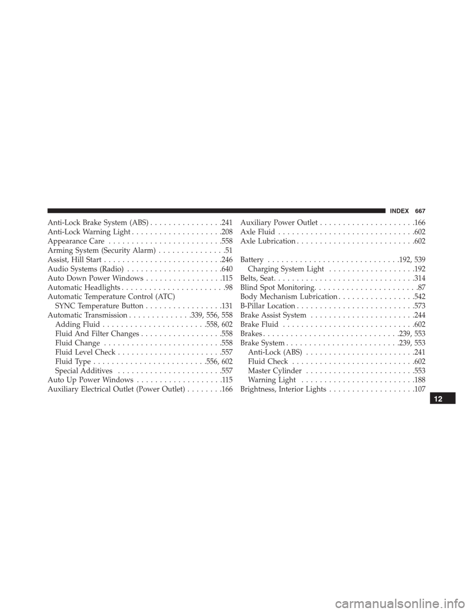
Anti-Lock Brake System (ABS)................241
Anti-Lock Warning Light....................208
Appearance Care.........................558
Arming System (Security Alarm)...............51
Assist, Hill Start..........................246
Audio Systems (Radio).....................640
Auto Down Power Windows.................115
Automatic Headlights.......................98
Automatic Temperature Control (ATC)
SYNC Temperature Button.................131
Automatic Transmission..............339, 556, 558
Adding Fluid.......................558, 602
Fluid And Filter Changes..................558
Fluid Change..........................558
Fluid Level Check.......................557
Fluid Type.........................556, 602
Special Additives.......................557
Auto Up Power Windows...................115
Auxiliary Electrical Outlet (Power Outlet)........166Auxiliary Power Outlet.....................166
Axle Fluid..............................602
Axle Lubrication..........................602
Battery.............................192, 539
Charging System Light...................192
Belts, Seat...............................314
Blind Spot Monitoring.......................87
Body Mechanism Lubrication.................542
B-Pillar Location..........................573
Brake Assist System.......................244
Brake Fluid.............................602
Brakes..............................239, 553
Brake System.........................239, 553
Anti-Lock (ABS)........................241
Fluid Check...........................602
Master Cylinder........................553
Warning Light.........................188
Brightness, Interior Lights...................107
12
INDEX 667