Page 297 of 723

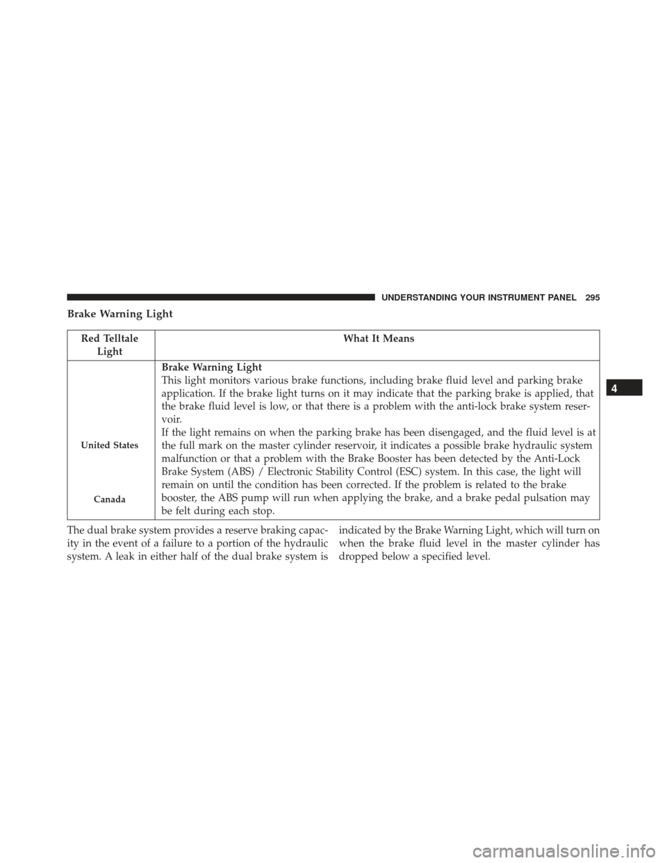
Brake Warning Light
Red TelltaleLight What It Means
United States
Canada
Brake Warning Light
This light monitors various brake functions, including brake fluid level and parking brake
application. If the brake light turns on it may indicate that the parking brake is applied, that
the brake fluid level is low, or that there is a problem with the anti-lock brake system reser-
voir.
If the light remains on when the parking brake has been disengaged, and the fluid level is at
the full mark on the master cylinder reservoir, it indicates a possible brake hydraulic system
malfunction or that a problem with the Brake Booster has been detected by the Anti-Lock
Brake System (ABS) / Electronic Stability Control (ESC) system. In this case, the light will
remain on until the condition has been corrected. If the problem is related to the brake
booster, the ABS pump will run when applying the brake, and a brake pedal pulsation may
be felt during each stop.
The dual brake system provides a reserve braking capac-
ity in the event of a failure to a portion of the hydraulic
system. A leak in either half of the dual brake system is indicated by the Brake Warning Light, which will turn on
when the brake fluid level in the master cylinder has
dropped below a specified level.
4
UNDERSTANDING YOUR INSTRUMENT PANEL 295
Page 298 of 723

The light will remain on until the cause is corrected.
NOTE:The light may flash momentarily during sharp
cornering maneuvers, which change fluid level condi-
tions. The vehicle should have service performed, and
the brake fluid level checked.
If brake failure is indicated, immediate repair is neces-
sary.
WARNING!
Driving a vehicle with the red brake light on is
dangerous. Part of the brake system may have failed.
It will take longer to stop the vehicle. You could have
a collision. Have the vehicle checked immediately.
Vehicles equipped with the Anti-Lock Brake System
(ABS) are also equipped with Electronic Brake Force Distribution (EBD). In the event of an EBD failure, the
Brake Warning Light will turn on along with the ABS
Light. Immediate repair to the ABS system is required.
Operation of the Brake Warning Light can be checked by
placing the ignition in the position ON/RUN position.
The light should illuminate for approximately two sec-
onds. The light should then turn off unless the parking
brake is applied or a brake fault is detected. If the light
does not illuminate, have the light inspected by an
authorized dealer.
The light also will turn on when the parking brake is
applied with the ignition is placed in the ON/RUN
position.
NOTE:
This light shows only that the parking brake is
applied. It does not show the degree of brake application.
296 UNDERSTANDING YOUR INSTRUMENT PANEL
Page 313 of 723
Anti-Lock Brake (ABS) Indicator Light
Yellow TelltaleLight What It Means
Anti-Lock Brake (ABS) Indicator Light
This light monitors the Anti-Lock Brake System (ABS). The light will turn on when the igni-
tion is placed in the ON/RUN position and may stay on for as long as four seconds.
If the ABS light remains on or turns on while driving, then the Anti-Lock portion of the
brake system is not functioning and service is required. However, the conventional brake
system will continue to operate normally if the brake warning light is not on.
If the ABS light is on, the brake system should be serviced as soon as possible to restore the
benefits of Anti-Lock Brakes. If the ABS light does not turn on when the ignition is placed in
the ON/RUN position, have the light inspected by an authorized dealer.
4
UNDERSTANDING YOUR INSTRUMENT PANEL 311
Page 329 of 723

OKbutton. To reset the oil change indicator system (after
performing the scheduled maintenance), refer to the
following procedure.
Oil Change Reset Procedure
1. Without pushing the brake pedal, push and release the ENGINE START/STOP button and place the ignition
to the ON/RUN position (do not start the engine).
2. Fully push the accelerator pedal, slowly, three times within 10 seconds.
3. Without pushing the brake pedal, push and release the ENGINE START/STOP button once to return the
ignition to the OFF/LOCK position.
NOTE: If the indicator message illuminates when you
start the vehicle, the oil change indicator system did not
reset. If necessary, repeat this procedure. Secondary Method For Oil Change Reset
1. Without depressing the brake pedal, push and release
the ENGINE START/STOP button and place the igni-
tion to the ON/RUN position (do not start the engine).
2. Navigate to �Oil Life�submenu in �Vehicle Info� on
DID.
3. Push and Hold the OKbutton until the gauge resets to
100%.
Performance Shift Indicator (PSI) – If Equipped
The Performance Shift Indicator (PSI) is enabled on
vehicles with manual transmission, or when a vehicle
with automatic transmission is in Auto-Stick mode. The
PSI provides the driver with a visual indication within
the cluster information display when the driver config-
ured gear shift point has been reached and the driver is
still accelerating. This indication notifies the driver to
change gear corresponding to the configured RPMs in the
4
UNDERSTANDING YOUR INSTRUMENT PANEL 327
Page 330 of 723

head unit. When the shift up indicator is shown on the
display, the PSI is advising the driver to engage a higher
gear.
NOTE:The PSI is configured and turned on or off in the
head unit “Shift Light: Set Up” page.
The PSI indicator in the cluster information display
remains illuminated until the driver changes gear, or the
driving conditions return to a situation where changing
gear is not required, corresponding to the configured
RPMs in the head unit.
NOTE: Refer to “Uconnect Settings” in “Understanding
Your Instrument Panel” for further information on en-
abling, disabling, and configuring the Performance Shift
Indicator.
DID Messages
Includes the following, but not limited to:
• Front Seatbelts Unbuckled •
Driver Seat Belt Unbuckled
• Passenger Seat Belt Unbuckled
• Traction Control Off
• Washer Fluid Low
• Oil Pressure Low
• Oil Change Due
• Fuel Low
• Service Anti-lock Brake System
• Service Electronic Throttle Control
• Service Power Steering
• Cruise Off
• Cruise Ready
• ACC Override
328 UNDERSTANDING YOUR INSTRUMENT PANEL
Page 350 of 723

Buttons On The Faceplate
Buttons on the faceplate are located below the Uconnect
system in the center of the instrument panel. In addition,
there is a Scroll/Enter control knob located on the right
side of the Climate Controls in the center of the instru-
ment panel. Turn the control knob to scroll through
menus and change settings (i.e., 30, 60, 90), push the
center of the control knob one or more times to select or
change a setting (i.e., ON, OFF).
Your Uconnect system may also have Screen Off and
Back buttons located below the Uconnect system.
Push the Screen Off button to turn off the Uconnect
touchscreen. Push the Screen Off button a second time to
turn the touchscreen on.
Push the Back button to exit out of a Menu or certain
option on the Uconnect system.
Buttons On The Touchscreen
Buttons on the touchscreen are accessible on the
Uconnect display.
Customer Programmable Features — Uconnect
8.4 Settings
Press the “Apps” button, then press the “Settings”
button on the touchscreen to display the menu setting
screen. In this mode the Uconnect system allows you
to access programmable features that may be
equipped such as Display, Units, Voice, Clock, Safety
& Driving Assistance, Lights, Doors & Locks, Auto-On
Comfort, Engine Off Options, Audio, Phone/
Bluetooth, SiriusXM Setup, Restore Settings, Clear
Personal Data, and System Information.
NOTE:
• Only one touchscreen area may be selected at a time.
348 UNDERSTANDING YOUR INSTRUMENT PANEL
Page 354 of 723

•Temperature
Select from: “°C,” or “°F.”
• Power
Select from: “HP” (US), “HP” (UK), and “kW.”
• Torque
Select from: “lb-ft” or “Nm.”
Voice
After pressing the “Voice” button on the touchscreen the
following settings will be available:
• Voice Response Length
When in this display, you may change the Voice Re-
sponse Length settings. To change the Voice Response
Length, press the “Brief” or “Detailed” button on the
touchscreen until a check-mark appears next to the
setting, showing that setting has been selected. •
Show Command List
When in this display, you may choose to Always, With
Help, or Never display the Teleprompter with possible
options while in a voice session. To change the Show
Command List settings, press the “Always,” “With
Help,” or “Never” button on the touchscreen until a
check-mark appears next to the setting, showing that
setting has been selected.
Clock
After pressing the “Clock” button on the touchscreen the
following settings will be available:
• Sync Time With GPS
This feature will allow the radio to sync time with a GPS
signal. To change the Sync Time setting, press the “Sync
time with GPS” button on the touchscreen until a check-
mark appears next to the setting, showing that setting has
been selected.
352 UNDERSTANDING YOUR INSTRUMENT PANEL
Page 355 of 723

•Set Time Hours
This feature will allow you to adjust the hours. The “Sync
time with GPS” button on the touchscreen must be
unchecked. To make your selection, press the “+” or “–”
buttons on the touchscreen to adjust the hours up or
down.
• Set Time Minutes
This feature will allow you to adjust the minutes. The
“Sync time with GPS” button on the touchscreen must be
unchecked. To make your selection, press the “+” or “–”
buttons on the touchscreen to adjust the minutes up or
down.
• Time Format
This feature will allow you to select the time format
display setting. Press the “Time Format” button on the touchscreen until a check-mark appears next to the “12
hrs” or “24 hrs” setting, showing that setting has been
selected.
•
Show Time In Status Bar — If Equipped
This feature will allow you to turn on or shut off the
digital clock in the status bar. To change the Show Time
Status setting press the “Show Time in Status Bar” button
on the touchscreen until a check-mark appears next to
setting, indicating that the setting has been selected.
Safety & Driving Assistance
After pressing the “Safety & Driving Assistance” button
on the touchscreen the following settings will be avail-
able:
• Forward Collision Warning — If Equipped
The Front Collision Warning (FCW) feature provides an
audible and/or visual warning to potential forward
collisions. This feature can is enabled by a setting in the
4
UNDERSTANDING YOUR INSTRUMENT PANEL 353