Page 548 of 723
CAUTION!(Continued)
damage. Stop the vehicle immediately if noise
occurs that could indicate device breakage. Remove
the damaged parts of the device before further use.
• Install device as tightly as possible and then re-
tighten after driving about ½ mile (0.8 km).
• Do not exceed 30 mph (48 km/h).
• Drive cautiously and avoid severe turns and large
bumps, especially with a loaded vehicle.
• Do not drive for a prolonged period on dry pave-
ment.
• Observe the traction device manufacturer ’s instruc-
tions on the method of installation, operating
speed, and conditions for use. Always use the
suggested operating speed of the device manufac-
turer ’s if it is less than 30 mph (48 km/h).
• Do not use traction devices on a compact spare tire.
TIRE ROTATION RECOMMENDATIONS
The tires on the front and rear of your vehicle operate at
different loads and perform different steering, handling,
and braking functions. For these reasons, they wear at
unequal rates.
These effects can be reduced by timely rotation of tires.
The benefits of rotation are especially worthwhile with
aggressive tread designs such as those on On/Off-Road
type tires. Rotation will increase tread life, help to main-
tain mud, snow, and wet traction levels, and contribute to
a smooth, quiet ride.
Refer to the “Maintenance Schedule” for the proper
maintenance intervals. More frequent rotation is permis-
sible if desired. The reasons for any rapid or unusual
wear should be corrected prior to rotation being per-
formed.
546 STARTING AND OPERATING
Page 570 of 723
of hitches are the most popular on the market today and
they are commonly used to tow small and medium sized
trailers.
Weight-Distributing Hitch
A weight-distributing system works by applying lever-
age through spring (load) bars. They are typically used
for heavier loads to distribute trailer tongue weight to the
tow vehicle’s front axle and the trailer axle(s). When used
in accordance with the manufacturer’s directions, it pro-
vides for a more level ride, offering more consistent
steering and brake control thereby enhancing towing
safety. The addition of a friction/hydraulic sway control
also dampens sway caused by traffic and crosswinds and
contributes positively to tow vehicle and trailer stability.
Trailer sway control and a weight distributing (load
equalizing) hitch are recommended for heavier Tongue
Weights (TW) and may be required depending on vehicleand trailer configuration/loading to comply with Gross
Axle Weight Rating (GAWR) requirements.
WARNING!
•
An improperly adjusted Weight Distributing Hitch
system may reduce handling, stability, braking
performance, and could result in a collision.
• Weight Distributing Systems may not be compat-
ible with Surge Brake Couplers. Consult with your
hitch and trailer manufacturer or a reputable Rec-
reational Vehicle dealer for additional information.
Trailer Hitch Classification
The following chart provides the industry standard for
the maximum trailer weight a given trailer hitch class can
tow and should be used to assist you in selecting the
correct trailer hitch for your intended towing condition.
568 STARTING AND OPERATING
Page 576 of 723
WARNING!(Continued)
cause a loss of control, poor performance or dam-
age to brakes, axle, engine, transmission, steering,
suspension, chassis structure or tires.
• Safety chains must always be used between your
vehicle and trailer. Always connect the chains to
the hook retainers of the vehicle hitch. Cross the
chains under the trailer tongue and allow enough
slack for turning corners.
• Vehicles with trailers should not be parked on a
grade. When parking, apply the parking brake on
the tow vehicle. Put the tow vehicle transmission in
PARK. For four-wheel drive vehicles, make sure
the transfer case is not in NEUTRAL. Always,
block or �chock�the trailer wheels.
• GCWR must not be exceeded.
(Continued)
WARNING! (Continued)
•Total weight must be distributed between the tow
vehicle and the trailer such that the following four
ratings are not exceeded:
1. GVWR
2. GTW
3. GAWR
4. Tongue weight rating for the trailer hitch uti-
lized.
574 STARTING AND OPERATING
Page 602 of 723
Disconnecting The Jumper Cables
1. Disconnect the negative(-)end of the jumper cable
from the remote negative (-)post of the discharged
vehicle.
2. Disconnect the opposite end of the negative (-)jumper
cable from the negative (-)post of the booster battery.
3. Disconnect the positive (+)end of the jumper cable
from the positive (+)post of the booster battery.
4. Disconnect the opposite end of the positive (+)jumper
cable from the remote positive (+)post of the dis-
charged vehicle.
5. Reinstall the protective cover over the remote positive (+) post of the discharged vehicle.
If frequent jump-starting is required to start your vehicle
you should have the battery and charging system tested
at your authorized dealer.CAUTION!
Accessories plugged into the vehicle power outlets
draw power from the vehicle’s battery, even when not
in use (i.e., cellular devices, etc.). Eventually, if
plugged in long enough without engine operation,
the vehicle’s battery will discharge sufficiently to
degrade battery life and/or prevent the engine from
starting.
FREEING A STUCK VEHICLE
If your vehicle becomes stuck in mud, sand or snow, it
can often be moved using a rocking motion. Turn the
steering wheel right and left to clear the area around the
front wheels. Push and hold the lock button on the gear
selector. Then shift back and forth between DRIVE and
REVERSE while gently pressing the accelerator.
600 WHAT TO DO IN EMERGENCIES
Page 659 of 723
FUSES
WARNING!
•When replacing a blown fuse, always use an appro-
priate replacement fuse with the same amp rating as
the original fuse. Never replace a fuse with another
fuse of higher amp rating. Never replace a blown
fuse with metal wires or any other material. Failure
to use proper fuses may result in serious personal
injury, fire and/or property damage.
(Continued)
WARNING! (Continued)
•Before replacing a fuse, make sure that the ignition
is off and that all the other services are switched off
and/or disengaged.
• If the replaced fuse blows again, contact an autho-
rized dealer.
• If a general protection fuse for safety systems (air
bag system, braking system), power unit systems
(engine system, gearbox system) or steering system
blows, contact an authorized dealer.
7
MAINTAINING YOUR VEHICLE 657
Page 663 of 723
CavityCartridge Fuse Micro Fuse Description
F40 –10 Amp Red Daytime Running Lights/Headlamp Lev-
eling
F42 –20 Amp Yellow Horn
F44 –10 Amp Red Diagnostic Port
F49 –10 Amp Red Integrated Central Stack / Climate Control
F50 –20 Amp Yellow Air Suspension Control Module - If
Equipped
F51 –15 Amp Blue Ignition Node Module / Keyless Ignition
/ Steering Column Lock
F52 –5 Amp Tan Battery Sensor
F53 –20 Amp Yellow Trailer Tow – Left Turn/Stop Lights - If
Equipped
F56 –15 Amp Blue Additional Content (Diesel engine only)
F57 –20 Amp Yellow NOX Sensor
F58 –15 Amp Blue HID Headlamps LH - If Equipped
7
MAINTAINING YOUR VEHICLE 661
Page 665 of 723
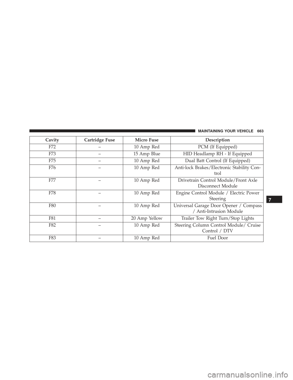
CavityCartridge Fuse Micro Fuse Description
F72 –10 Amp Red PCM (If Equipped)
F73 –15 Amp Blue HID Headlamp RH - If Equipped
F75 –10 Amp Red Dual Batt Control (If Equipped)
F76 –10 Amp Red Anti-lock Brakes/Electronic Stability Con-
trol
F77 –10 Amp Red Drivetrain Control Module/Front Axle
Disconnect Module
F78 –10 Amp Red Engine Control Module / Electric Power
Steering
F80 –10 Amp Red Universal Garage Door Opener / Compass
/ Anti-Intrusion Module
F81 –20 Amp Yellow Trailer Tow Right Turn/Stop Lights
F82 –10 Amp Red Steering Column Control Module/ Cruise
Control / DTV
F83 –10 Amp Red Fuel Door
7
MAINTAINING YOUR VEHICLE 663
Page 666 of 723
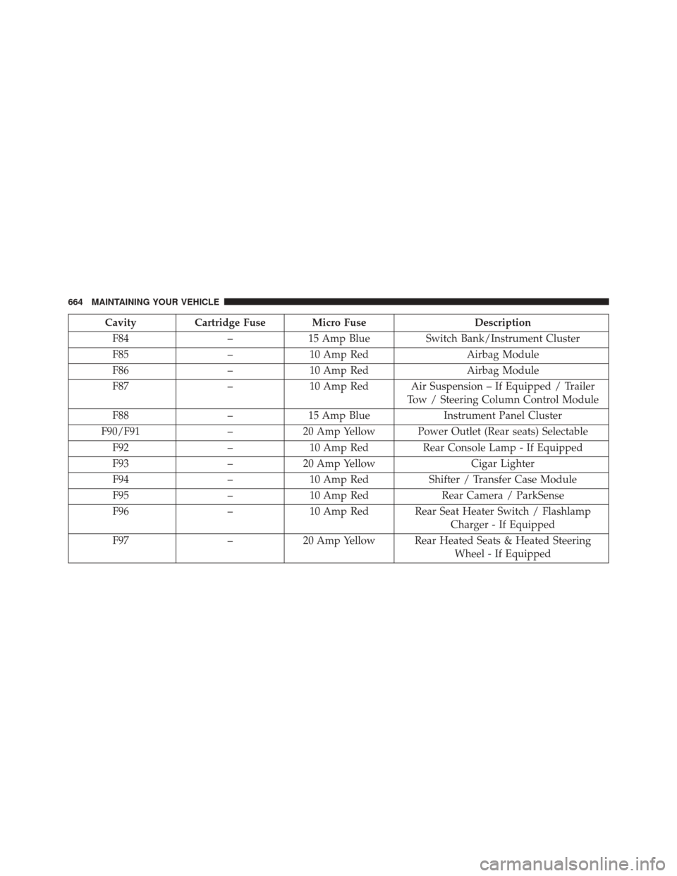
CavityCartridge Fuse Micro Fuse Description
F84 –15 Amp Blue Switch Bank/Instrument Cluster
F85 –10 Amp Red Airbag Module
F86 –10 Amp Red Airbag Module
F87 –10 Amp Red Air Suspension – If Equipped / Trailer
Tow / Steering Column Control Module
F88 –15 Amp Blue Instrument Panel Cluster
F90/F91 –20 Amp Yellow Power Outlet (Rear seats) Selectable
F92 –10 Amp Red Rear Console Lamp - If Equipped
F93 –20 Amp Yellow Cigar Lighter
F94 –10 Amp Red Shifter / Transfer Case Module
F95 –10 Amp Red Rear Camera / ParkSense
F96 –10 Amp Red Rear Seat Heater Switch / Flashlamp
Charger - If Equipped
F97 –20 Amp Yellow Rear Heated Seats & Heated Steering
Wheel - If Equipped
664 MAINTAINING YOUR VEHICLE