Page 457 of 745
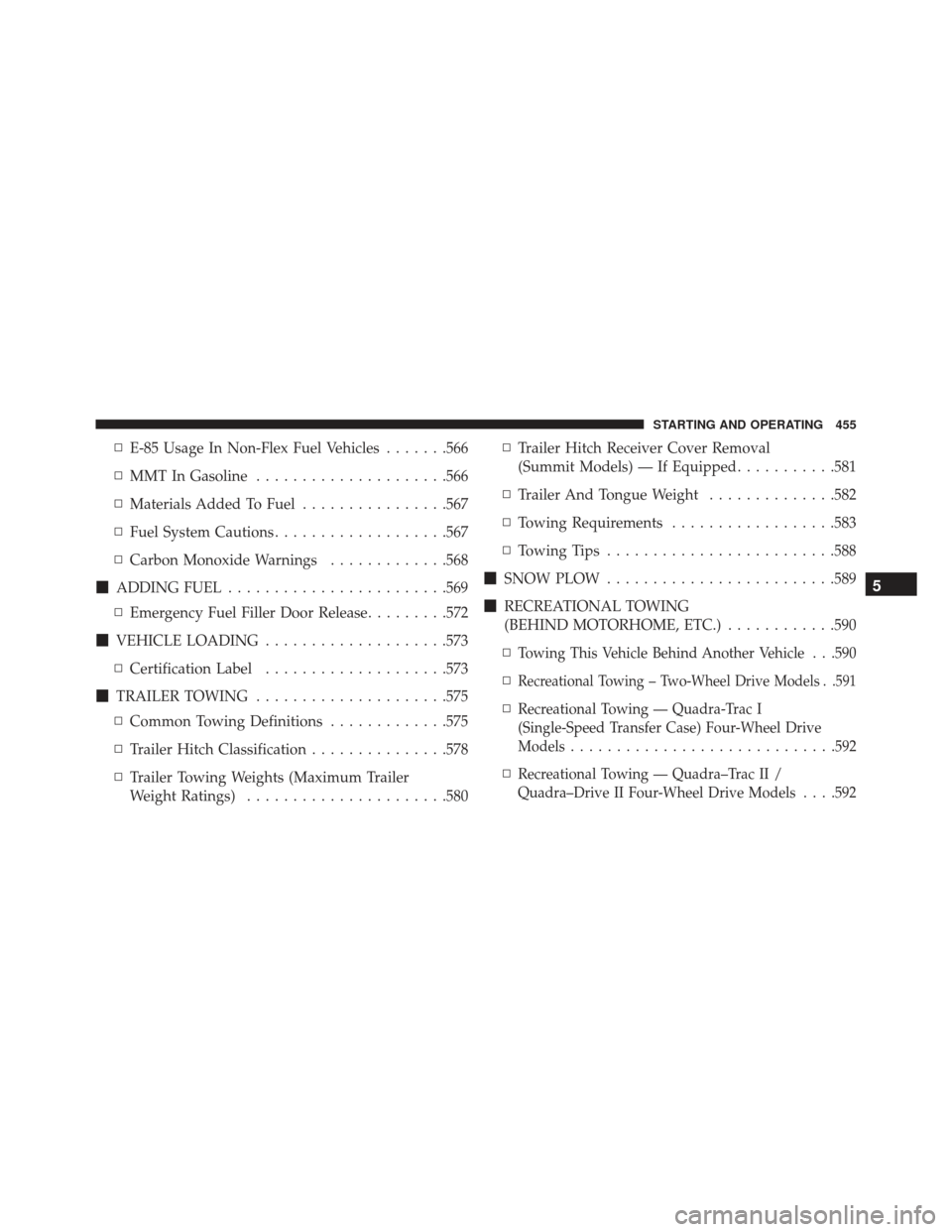
▫E-85 Usage In Non-Flex Fuel Vehicles .......566
▫ MMT In Gasoline .....................566
▫ Materials Added To Fuel ................567
▫ Fuel System Cautions ...................567
▫ Carbon Monoxide Warnings .............568
� ADDING FUEL ....................... .569
▫ Emergency Fuel Filler Door Release .........572
� VEHICLE LOADING ....................573
▫ Certification Label ....................573
� TRAILER TOWING .....................575
▫ Common Towing Definitions .............575
▫ Trailer Hitch Classification ...............578
▫ Trailer Towing Weights (Maximum Trailer
Weight Ratings) ..................... .580▫
Trailer Hitch Receiver Cover Removal
(Summit Models) — If Equipped ...........581
▫ Trailer And Tongue Weight ..............582
▫ Towing Requirements ..................583
▫ Towing Tips ........................ .588
� SNOW PLOW ........................ .589
� RECREATIONAL TOWING
(BEHIND MOTORHOME, ETC.) ............590
▫
Towing This Vehicle Behind Another Vehicle . . .590
▫Recreational Towing – Two-Wheel Drive Models . .591
▫Recreational Towing — Quadra-Trac I
(Single-Speed Transfer Case) Four-Wheel Drive
Models ............................ .592
▫Recreational Towing — Quadra–Trac II /
Quadra–Drive II Four-Wheel Drive Models . . . .592
5
STARTING AND OPERATING 455
Page 500 of 745
NOTE:Some alignment may be required upon fascia
installation to align sensor with fascia.
4. Install the wiring harness connector into the radar sensor.
NOTE: If you receive a fault, see your authorized dealer
they may need to perform a sensor alignment.
Lower Front Fascia Installation
NOTE: This will only work if you have a helper.
1. Starting at the center of the vehicle, engage a sufficient number of tabs to support the weight of the lower
fascia (typically one or two tabs) into the upper fascia.
2. Working your way outward, engage the tabs into the slots on one side of the vehicle.
3. Return to the center of the vehicle and repeat Step 2 to the opposite side of the vehicle. NOTE:
•It may be necessary to apply additional force to
individual tabs to make sure they are fully engaged.
• Do not use any tools to apply additional force to the
tabs as damage to the upper and lower fascias may
result.
4. Reinstall the seven quarter turn fasteners.
Quadra-Lift — If Equipped
When off-roading, it is recommended that the lowest
useable vehicle height that will clear the current obstacle
or terrain be selected. The vehicle height should then be
raised as required by the changes in terrain.
The Selec-Terrain switch will automatically change the
vehicle to the optimized height based on the Selec-
Terrain switch position. The vehicle height can be
changed from the default height for each Selec-Terrain
498 STARTING AND OPERATING
Page 523 of 745

swaying. Always use caution when towing a trailer and
follow the trailer tongue weight recommendations. Refer
to “Trailer Towing” in this section for further informa-
tion.
When TSC is functioning, the “ESC Activation/
Malfunction Indicator Light” will flash, the engine power
may be reduced and you may feel the brakes being
applied to individual wheels to attempt to stop the trailer
from swaying. TSC is disabled when the ESC system is in
the “Partial Off” or “Full Off” modes.
WARNING!
If TSC activates while driving, slow the vehicle
down, stop at the nearest safe location, and adjust the
trailer load to eliminate trailer sway.
Ready Alert Braking (RAB)
Ready Alert Braking may reduce the time required to
reach full braking during emergency braking situations.
It anticipates when an emergency braking situation may
occur by monitoring how fast the throttle is released by
the driver. The EBC will prepare the brake system for a
panic stop.
Rain Brake Support (RBS)
Rain Brake Support may improve braking performance
in wet conditions. It will periodically apply a small
amount of brake pressure to remove any water buildup
on the front brake rotors. It functions when the wind-
shield wipers are in LO or HI speed. When Rain Brake
Support is active, there is no notification to the driver and
no driver interaction is required.
5
STARTING AND OPERATING 521
Page 539 of 745
Tire And Loading Information PlacardThis placard tells you important information about the:
1. Number of people that can be carried in the vehicle.
2. Total weight your vehicle can carry.
3. Tire size designed for your vehicle.
4. Cold tire inflation pressures for the front, rear, andspare tires.
Loading
The vehicle maximum load on the tire must not exceed
the load carrying capacity of the tire on your vehicle. You
will not exceed the tire’s load carrying capacity if you
adhere to the loading conditions, tire size, and cold tire
inflation pressures specified on the Tire and Loading
Information placard in “Vehicle Loading” in the “Starting
And Operating” section of this manual.
Tire And Loading Information Placard
5
STARTING AND OPERATING 537
Page 540 of 745
NOTE:Under a maximum loaded vehicle condition,
gross axle weight ratings (GAWRs) for the front and rear
axles must not be exceeded. For further information on
GAWRs, vehicle loading, and trailer towing, refer to
“Vehicle Loading” in the “Starting And Operating” sec-
tion of this manual.
To determine the maximum loading conditions of your
vehicle, locate the statement “The combined weight of
occupants and cargo should never exceed XXX lbs or
XXX kg” on the Tire and Loading Information placard.
The combined weight of occupants, cargo/luggage and
trailer tongue weight (if applicable) should never exceed
the weight referenced here. Steps For Determining Correct Load Limit
1. Locate the statement “The combined weight of occu-
pants and cargo should never exceed XXX lbs or
XXX kg” on your vehicle’s placard.
2. Determine the combined weight of the driver and passengers that will be riding in your vehicle.
3. Subtract the combined weight of the driver and pas- sengers from XXX lbs or XXX kg.
538 STARTING AND OPERATING
Page 541 of 745
4. The resulting figure equals the available amount ofcargo and luggage load capacity. For example, if
“XXX” amount equals 1,400 lbs (635 kg) and there will
be five 150 lb (68 kg) passengers in your vehicle, the
amount of available cargo and luggage load capacity
is 650 lbs (294 kg) (since 5 x 150 lbs (68 kg) = 750 lbs
(340 kg), and 1400 lbs (635 kg) – 750 lbs (340 kg) =
650 lbs [294 kg]).
5. Determine the combined weight of luggage and cargo being loaded on the vehicle. That weight may not
safely exceed the available cargo and luggage load
capacity calculated in step 4. NOTE:
•
If your vehicle will be towing a trailer, load from your
trailer will be transferred to your vehicle. The follow-
ing table shows examples on how to calculate total
load, cargo/luggage, and towing capacities of your
vehicle with varying seating configurations and num-
ber and size of occupants. This table is for illustration
purposes only and may not be accurate for the seating
and load carry capacity of your vehicle.
• For the following example, the combined weight of
occupants and cargo should never exceed 865 lbs
(392 kg).
5
STARTING AND OPERATING 539
Page 575 of 745
VEHICLE LOADING
Certification Label
As required by National Highway Traffic Safety Admin-
istration regulations, your vehicle has a certification label
affixed to the driver’s side door or pillar.
This label contains the month and year of manufacture,
Gross Vehicle Weight Rating (GVWR), Gross Axle Weight
Rating (GAWR) front and rear, and Vehicle Identification
Number (VIN). A Month-Day-Hour (MDH) number is
included on this label and indicates the Month, Day and
Hour of manufacture. The bar code that appears on the
bottom of the label is your VIN.
Gross Vehicle Weight Rating (GVWR)
The GVWR is the total permissible weight of your vehicle
including driver, passengers, vehicle, options and cargo.
The label also specifies maximum capacities of front andrear axle systems (GAWR). Total load must be limited so
GVWR and front and rear GAWR are not exceeded.
Payload
The payload of a vehicle is defined as the allowable load
weight a truck can carry, including the weight of the
driver, all passengers, options and cargo.
Gross Axle Weight Rating (GAWR)
The GAWR is the maximum permissible load on the front
and rear axles. The load must be distributed in the cargo
area so that the GAWR of each axle is not exceeded.
Each axle GAWR is determined by the components in the
system with the lowest load carrying capacity (axle,
springs, tires or wheels). Heavier axles or suspension
components sometimes specified by purchasers for in-
creased durability does not necessarily increase the vehi-
cle’s GVWR.
5
STARTING AND OPERATING 573
Page 576 of 745
Tire Size
The tire size on the Vehicle Certification Label represents
the actual tire size on your vehicle. Replacement tires
must be equal to the load capacity of this tire size.
Rim Size
This is the rim size that is appropriate for the tire size
listed.
Inflation Pressure
This is the cold tire inflation pressure for your vehicle for
all loading conditions up to full GAWR.
Curb Weight
The curb weight of a vehicle is defined as the total weight
of the vehicle with all fluids, including vehicle fuel, at full
capacity conditions, and with no occupants or cargo loaded
into the vehicle. The front and rear curb weight values are
determined by weighing your vehicle on a commercial
scale before any occupants or cargo are added.
Loading
The actual total weight and the weight of the front and
rear of your vehicle at the ground can best be determined
by weighing it when it is loaded and ready for operation.
The entire vehicle should first be weighed on a commer-
cial scale to insure that the GVWR has not been exceeded.
The weight on the front and rear of the vehicle should
then be determined separately to be sure that the load is
properly distributed over the front and rear axle. Weigh-
ing the vehicle may show that the GAWR of either the
front or rear axles has been exceeded but the total load is
within the specified GVWR. If so, weight must be shifted
from front to rear or rear to front as appropriate until the
specified weight limitations are met. Store the heavier
items down low and be sure that the weight is distributed
equally. Stow all loose items securely before driving.
574 STARTING AND OPERATING