Page 344 of 406

Maintenance
34 7
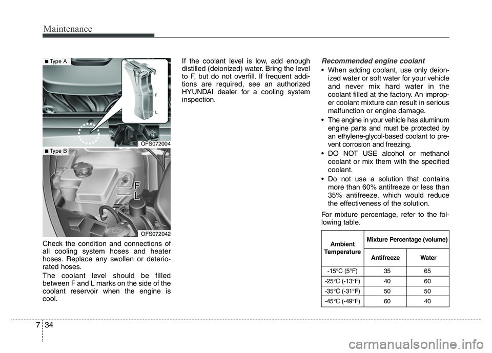
Check the condition and connections of
all cooling system hoses and heater
hoses. Replace any swollen or deterio-
rated hoses.
The coolant level should be filled
between F and L marks on the side of the
coolant reservoir when the engine is
cool.If the coolant level is low, add enough
distilled (deionized) water. Bring the level
to F, but do not overfill. If frequent addi-
tions are required, see an authorized
HYUNDAI dealer for a cooling system
inspection.
Recommended engine coolant
• When adding coolant, use only deion-
ized water or soft water for your vehicle
and never mix hard water in the
coolant filled at the factory. An improp-
er coolant mixture can result in serious
malfunction or engine damage.
• The engine in your vehicle has aluminum
engine parts and must be protected by
an ethylene-glycol-based coolant to pre-
vent corrosion and freezing.
• DO NOT USE alcohol or methanol
coolant or mix them with the specified
coolant.
• Do not use a solution that contains
more than 60% antifreeze or less than
35% antifreeze, which would reduce
the effectiveness of the solution.
For mixture percentage, refer to the fol-
lowing table.
OFS072004
OFS072042
■Type A
■ Type B
-15°C (5°F) 35 65
-25°C (-13°F) 40 60
-35°C (-31°F) 50 50
-45°C (-49°F) 60 40
Ambient
TemperatureMixture Percentage (volume)
AntifreezeWater
Page 345 of 406
735
Maintenance
Changing the coolant
Have coolant changed by an authorized
HYUNDAI dealer according to the
Maintenance Schedule at the beginning
of this section.
WARNING
Radiator cap
Do not remove the radiator cap
when the engine and radiator are
hot. Scalding hot coolant and
steam may blow out under pres-
sure causing serious injury.
WARNING- Coolant
• Do not use radiator coolant or
antifreeze in the washer fluid
reservoir.
• Radiator coolant can severely
obscure visibility when sprayed
on the windshield and may cause
loss of vehicle control or damage
to paint and body trim.
CAUTION
Put a thick cloth or fabric around
the radiator cap before refilling the
coolant in order to prevent the
coolant from overflowing into
engine parts such as generator.
OFS072005
Page 395 of 406

785
Maintenance
EMISSION CONTROL SYSTEM
The emission control system of your
vehicle is covered by a written limited
warranty. Please see the warranty infor-
mation contained in the Service Passport
your vehicle.
Your vehicle is equipped with an emis-
sion control system to meet all applicable
emission regulations.
There are three emission control sys-
tems, as follows.
(1) Crankcase emission control system
(2) Evaporative emission control system
(3) Exhaust emission control system
In order to assure the proper function of
the emission control systems, it is recom-
mended that you have your car inspected
and maintained by an authorized
HYUNDAI dealer in accordance with the
maintenance schedule in this manual.Caution for the Inspection and
Maintenance Test (With Electronic
Stability Control (ESC) system)
• To prevent the vehicle from misfir-
ing during dynamometer testing,
turn the Electronic Stability Control
(ESC) system off by pressing the
ESC switch.
• After dynamometer testing is com-
pleted, turn the ESC system back on
by pressing the ESC switch again.
1. Crankcase emission control
system
The positive crankcase ventilation sys-
tem is employed to prevent air pollution
caused by blow-by gases being emitted
from the crankcase. This system supplies
fresh filtered air to the crankcase through
the air intake hose. Inside the crankcase,
the fresh air mixes with blow-by gases,
which then pass through the PCV valve
into the induction system.
2. Evaporative emission control
(including ORVR: Onboard
Refueling Vapor Recovery)
system
The Evaporative Emission Control
System is designed to prevent fuel vapors
from escaping into the atmosphere.
(The ORVR system is designed to allow
the vapors from the fuel tank to be
loaded into a canister while refueling at
the gas station, preventing the escape of
fuel vapors into the atmosphere.)
Canister
Fuel vapors generated inside the fuel
tank are absorbed and stored in the
onboard canister. When the engine is
running, the fuel vapors absorbed in the
canister are drawn into the surge tank
through the purge control solenoid valve.
Purge Control Solenoid Valve (PCSV)
The purge control solenoid valve is con-
trolled by the Engine Control Module
(ECM); when the engine coolant tempera-
ture is low during idling, the PCSV closes
so that evaporated fuel is not taken into
the engine. After the engine warms-up
during ordinary driving, the PCSV opens
to introduce evaporated fuel to the engine.
Page 403 of 406
Specifications & Consumer information
6 8
*1Refer to the recommended SAE viscosity numbers on the next page.
*2Engine oils labeled Energy Conserving Oil are now available. Along with other additional benefits, they contribute to fuel econ-
omy by reducing the amount of fuel necessary to overcome engine friction. Often, these improvements are difficult to measure
in everyday driving, but in a year’s time, they can offer significant cost and energy savings.
*
3If the API service SM engine oil is not available in your country, you may substitute API service SL.
LubricantVolumeClassification
Coolant
Automatic transaxle5.2 l(5.5 US qt.)Mixture of antifreeze and water
(Ethylene glycol base coolant for aluminum radiator)Manual Transaxle5.0 l(5.28 US qt.)Ecoshift dual clutch transmission
Brake/clutch fluid0.7~0.8 l
(0.7~0.8 US qt.)FMVSS116 DOT-3 or DOT-4
Fuel50 l(13.2 US gal.)Unleaded gasoline
Page:
< prev 1-8 9-16 17-24