Page 547 of 642

7-34
Maintenance
Recommended engine coolant
When adding coolant, use onlydeionized water, distilled water or
soft water for your vehicle and
never mix hard water in the coolant
filled at the factory.
An improper coolant mixture can result in severe malfunction or
engine damage.
The engine in your vehicle has alu- minum engine parts and must be
protected by an phosphate-based
ethylene glycol coolant to preventcorrosion and freezing.
Do not use alcohol or methanol coolant or mix them with the spec-ified coolant.
Do not use a solution that contains more than 60% antifreeze or less
than 35% antifreeze, which would
reduce the effectiveness of thesolution. For mixing percentage, refer to the
following table:
Information
If in doubt about the mix ratio, a 50%
water and 50% antifreeze mix is the
easiest to mix together as it will be the
same quantity of each.
It is suitable to use for most tempera-
ture ranges of -31°F and higher.
i
(Continued)
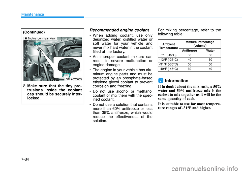
2. Make sure that the tiny pro-
trusions inside the coolant
cap should be securely inter-
locked.
OTLA075063
■Engine room rear view
Ambient
Temperature Mixture Percentage
(volume)
Antifreeze Water
5°F (-15°C) 35 65
-13°F (-25°C) 40 60
-31°F (-35°C) 50 50
-49°F (-45°C) 60 40
Page 550 of 642

7-37
7
Maintenance
WWAASSHH EERR FF LLUU IIDD
Checking the Washer Fluid
Level
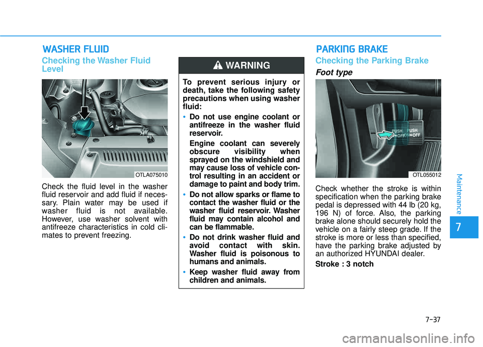
Check the fluid level in the washer
fluid reservoir and add fluid if neces-
sary. Plain water may be used if
washer fluid is not available.
However, use washer solvent with
antifreeze characteristics in cold cli-
mates to prevent freezing.
Checking the Parking Brake
Foot type
Check whether the stroke is within
specification when the parking brakepedal is depressed with 44 lb (20 kg,
196 N) of force. Also, the parking
brake alone should securely hold the
vehicle on a fairly steep grade. If the
stroke is more or less than specified,
have the parking brake adjusted by
an authorized HYUNDAI dealer.
Stroke : 3 notch
OTLA075010OTL055012
PP AA RRKK IINN GG BB RRAA KKEE
To prevent serious injury or
death, take the following safetyprecautions when using washerfluid:
Do not use engine coolant or
antifreeze in the washer fluid
reservoir.
Engine coolant can severely obscure visibility when
sprayed on the windshield and
may cause loss of vehicle con-
trol resulting in an accident or
damage to paint and body trim.
Do not allow sparks or flame to contact the washer fluid or the
washer fluid reservoir. Washer
fluid may contain alcohol and
can be flammable.
Do not drink washer fluid and
avoid contact with skin.
Washer fluid is poisonous tohumans and animals.
Keep washer fluid away from
children and animals.
WARNING
Page 552 of 642
7-39
7
Maintenance
4. Replace the air cleaner filter. 5. Pull up the lever (1) to the LOCKposition.
6. Rise up the cover (2) until the hooks on the cover are securely
fastened into the latches (3).
7. Check if the cover is firmly installed.
Information
If the vehicle is operated in extremely
dusty or sandy areas, replace the ele-
ment more often than the usual rec-
ommended intervals (refer to
"Maintenance Under Severe Usage
Conditions" in this chapter).
Do not drive with the air cleanerfilter removed. This will result in
excessive engine wear.
When removing the air cleaner filter, be careful that dust or dirt
does not enter the air intake, or
damage may result.
Use HYUNDAI genuine parts, use of non-genuine parts could
damage the air flow sensor.
NOTICE
i
OTL075017OTL075018
Page 559 of 642

7-46
Maintenance
When you do not use the vehiclefor a long time in a low tempera-
ture area, disconnect the battery
and keep it indoors.
Always charge the battery fully to prevent battery case damage
in low temperature areas.
For Best Battery Service
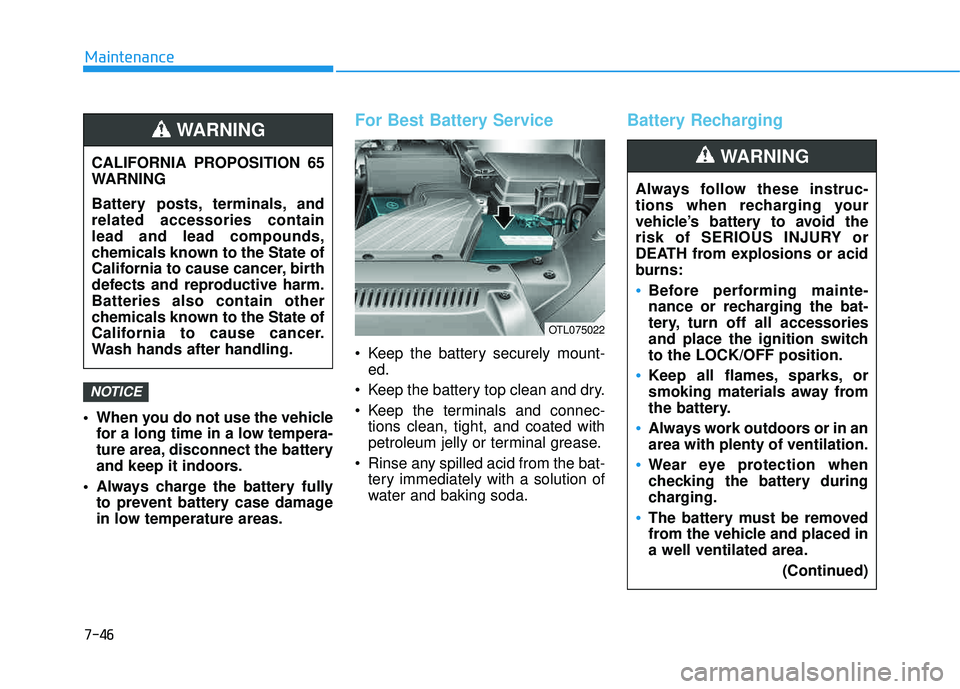
Keep the battery securely mount-ed.
Keep the battery top clean and dry.
Keep the terminals and connec- tions clean, tight, and coated with
petroleum jelly or terminal grease.
Rinse any spilled acid from the bat- tery immediately with a solution of
water and baking soda.
Battery Recharging
NOTICE
CALIFORNIA PROPOSITION 65
WARNING
Battery posts, terminals, and related accessories containlead and lead compounds,
chemicals known to the State of
California to cause cancer, birth
defects and reproductive harm.Batteries also contain other
chemicals known to the State of
California to cause cancer.
Wash hands after handling.
WARNING
Always follow these instruc-
tions when recharging your
vehicle’s battery to avoid the
risk of SERIOUS INJURY or
DEATH from explosions or acid
burns:
Before performing mainte-
nance or recharging the bat-
tery, turn off all accessories
and place the ignition switchto the LOCK/OFF position.
Keep all flames, sparks, or
smoking materials away from
the battery.
Always work outdoors or in an area with plenty of ventilation.
Wear eye protection when
checking the battery during
charging.
The battery must be removed
from the vehicle and placed ina well ventilated area.
(Continued)
WARNING
OTL075022
Page 580 of 642
7-67
7
Maintenance
Main fuse
If the main fuse is blown, it must be
removed as follows:
1. Turn off the engine.
2. Disconnect the negative batterycable.
3. Remove the fuse panel cover by pressing the tab and pulling it up.
4. Remove the nuts shown in the pic- ture above.
5. Replace the fuse with a new one of the same rating.
6. Reinstall in the reverse order of removal.
Information
If the main fuse is blown, consult an
authorized HYUNDAI dealer.
i
After checking the fuse box in
the engine compartment
securely close the fuse box
cover inside the engine com-
partment, until it clicks.
If the fuse box is not closed
properly, water may leak in side,
possibly causing a malfunctionwith the electrical system.
CAUTION
OTLA075027
Page 584 of 642

7-71
7
Maintenance
Instrument panel fuse panel
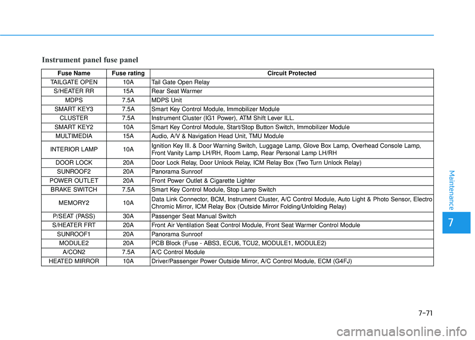
Fuse Name Fuse ratingCircuit Protected
TAILGATE OPEN 10A Tail Gate Open Relay
S/HEATER RR 15A Rear Seat Warmer MDPS 7.5A MDPS Unit
SMART KEY3 7.5A Smart Key Control Module, Immobilizer Module
CLUSTER 7.5A Instrument Cluster (IG1 Power), ATM Shift Lever ILL.
SMART KEY2 10A Smart Key Control Module, Start/Stop Button Switch, Immobilizer Module MULTIMEDIA 15A Audio, A/V & Navigation Head Unit, TMU Module
INTERIOR LAMP 10A Ignition Key Ill. & Door Warning Switch, Luggage Lamp, Glove Box Lamp, Overhead Console Lamp,
Front Vanity Lamp LH/RH, Room Lamp, Rear Personal Lamp LH/RH
DOOR LOCK 20A Door Lock Relay, Door Unlock Relay, ICM Relay Box (Two Turn Unlock Relay) SUNROOF2 20A Panorama Sunroof
POWER OUTLET 20A Front Power Outlet & Cigarette Lighter BRAKE SWITCH 7.5A Smart Key Control Module, Stop Lamp Switch
MEMORY2 10A Data Link Connector, BCM, Instrument Cluster, A/C Control Module, Auto Light & Photo Sensor, Electro
Chromic Mirror, ICM Relay Box (Outside Mirror Folding/Unfolding Relay)
P/SEAT (PASS) 30A Passenger Seat Manual Switch
S/HEATER FRT 20A Front Air Ventilation Seat Control Module, Front Seat Warmer Control Module
SUNROOF1 20A Panorama Sunroof
MODULE2 20A PCB Block (Fuse - ABS3, ECU6, TCU2, MODULE1, MODULE2) A/CON2 7.5A A/C Control Module
HEATED MIRROR 10A Driver/Passenger Power Outside Mirror, A/C Control Module, ECM (G4FJ)
Page 588 of 642
![HYUNDAI TUCSON 2016 Owners Manual 7-75
7
Maintenance
Engine compartment main fuse panel
Fuse Name Fuse ratingCircuit Protected
WIPER FRT1 25A Ignition Switch (W/O Smart Key), PDM (IG2) Relay (With Smart Key)
TCU1 15A [G4FJ] TCM HYUNDAI TUCSON 2016 Owners Manual 7-75
7
Maintenance
Engine compartment main fuse panel
Fuse Name Fuse ratingCircuit Protected
WIPER FRT1 25A Ignition Switch (W/O Smart Key), PDM (IG2) Relay (With Smart Key)
TCU1 15A [G4FJ] TCM](/manual-img/35/56201/w960_56201-587.png)
7-75
7
Maintenance
Engine compartment main fuse panel
Fuse Name Fuse ratingCircuit Protected
WIPER FRT1 25A Ignition Switch (W/O Smart Key), PDM (IG2) Relay (With Smart Key)
TCU1 15A [G4FJ] TCM (7DCT)
WIPER FRT2 10A BCM ECU3 20A PCM (G4NC) / ECM (G4FJ)
HORN 15A Horn Relay
BATTERY
MANAGEMENT 10A Battery
Sensor
SENSOR2 10A [G4NC] Oil Control Valve #1/#2, Camshaft Position Sensor #1/#2, Purge Control Solenoid Valve,
Variable Intake Solenoid Valve, Canister Close Valve, Fuel Pump Relay
[G4FJ] Oil Control Valve #1/#2, Purge Control Solenoid Valve, Canister Close Valve, Fuel Pump Relay
SENSOR1 15A [G4NC] PCM, Oxygen Sensor (Up)/(Down) [G4FJ] ECM, Oxygen Sensor (Up)/(Down) ECU2 20A IGNITION COIL #1/#2/#3/#4, Condenser (G4NC)
ECU5 15A PCM (G4NC) / ECM (G4FJ)
ECU4 15A PCM (G4NC) / ECM (G4FJ)
SENSOR3 10A [G4NC] E/R Junction Block (Cooling Fan High Relay)
[G4FJ] Brake Vacuum Switch, RCV Control Solenoid Valve, E/R Junction Block (Cooling Fan High
Relay)
DEICER 15A E/R Junction Block (Front Deicer Relay)
FUEL PUMP1 20A Fuel Pump Relay
MODULE1 7.5A Adaptive Front Lighting Module
B/ALARM HORN 10A E/R Junction Block (B/Alarm Horn Relay) ABS3 10A ESC Module
Page 589 of 642
7-76
Maintenance
Engine compartment main fuse panel
Fuse Name Fuse ratingCircuit Protected
MODULE2 10A [G4FJ] Vacuum Pump
POWER OUTLER FRT 20A Front Power Outlet & Cigarette Lighter
ECU6 10A PCM (G4NC) / ECM (G4FJ) TCU2 15A Transaxle Range Switch, TCM (G4FJ - 7DCT)
B/UP LAMP 10A PCM (G4NC) / TCM (G4FJ), Transaxle Range Switch, Audio, A/V & Navigation Head Unit, Electro
Chromic Mirror, Rear Combination Lamp (IN) LH/RH
POWER OUTLER REAR 20A Rear
Power Outlet
ECU1 30A Engine Control Relay