2016 Hyundai Santa Fe Sport start
[x] Cancel search: startPage 7 of 763
1
2
3
4
5
6
7
8I
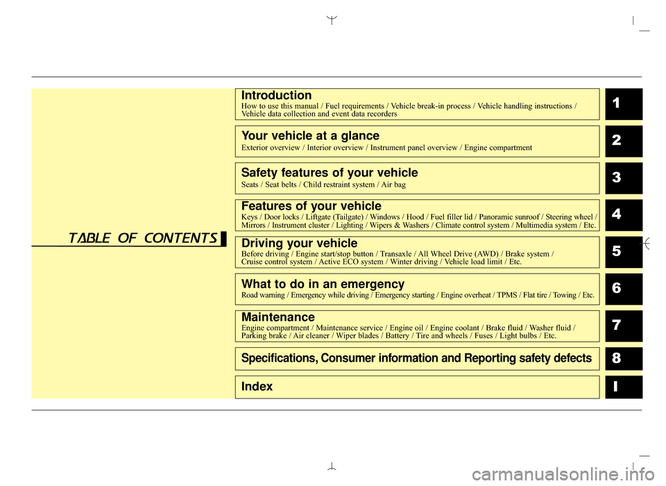
IntroductionHow to use this manual / Fuel requirements / Vehicle break-in process / Vehicle handling instructions /Vehicle data collection and event data recorders
Your vehicle at a glance
Exterior overview / Interior overview / Instrument panel overview / Engi\
ne compartment
Safety features of your vehicle
Seats / Seat belts / Child restraint system / Air bag
Features of your vehicleKeys / Door locks / Liftgate (Tailgate) / Windows / Hood / Fuel filler lid / Panoramic sunroof / Steering wheel /
Mirrors / Instrument cluster / Lighting / Wipers & Washers / Climate control system / Multimedia system / Etc.
Driving your vehicleBefore driving / Engine start/stop button / Transaxle / All Wheel Drive (AWD) / Brake system /
Cruise control system / Active ECO system / Winter driving / Vehicle load limit / Etc.
What to do in an emergencyRoad warning / Emergency while driving / Emergency starting / Engine overheat / TPMS / Flat tire / Towing / Etc.
MaintenanceEngine compartment / Maintenance service / Engine oil / Engine coolant /\
Brake fluid / Washer fluid /
Parking brake / Air cleaner / Wiper blades / Battery / Tire and wheels / Fuses / Light bulbs / Etc.
Specifications, Consumer information and Reporting safety defects
Index
table of contents
AN HMA FOREWORD.QXP 2015-05-07 ¿ ¨˜ 4:12 Page 7
Page 9 of 763
Introduction
21
We want to help you get the greatest
possible driving experience from your
vehicle. Your Owner’s Manual can
assist you in many ways. We strongly
recommend that you read the entire
manual. In order to minimize the
chance of death or injury, you must
read the WARNING and CAUTION
sections in the manual. Illustrations
complement the text in this manual to
best explain how to use your vehicle.
By reading your manual, you will
learn about features, important safety
information, and driving tips under
various road conditions. The general
layout of the manual is provided in
the Table of Contents. A good place
to start is the index; it has an alpha-
betical listing of all information in your
manual. Sections: This manual has
eight sections plus an index. Each
section begins with a brief list of con-
tents so you can tell at a glance if that
section has the information you want.
You will find various WARNINGS,
CAUTIONS, and NOTICES in this
manual. These WARNINGS were pre-
pared to enhance your personal safe-
ty. You should carefully read and follow
ALL procedures and recommenda-
tions provided in these WARNINGS,
CAUTIONS and NOTICES.Symbols used in this manual
Warnings, Cautions and Notices
✽ ✽NOTICE
A NOTICE indicates interesting or
helpful information is being provided.
Safety symbol in illustrations
The symbol means to "Avoid"
or "Do not do something". Your new vehicle is designed to obtain
maximum performance with UNLEAD-
ED FUEL, as well as minimize exhaust
emissions and spark plug fouling.
Your new vehicle is designed to use
only unleaded fuel having a pump
octane number ((R+M)/2) of 87
(Research Octane Number 91) or
higher. (Do not use methanol blended
fuels.)
Never add any fuel system cleaning
agents to the fuel tank other than what
has been specified. (Consult an
authorized HYUNDAI dealer for
details.)
HOW TO USE THIS MANUAL
WARNING
A WARNING indicates that a
condition may result in harm,
serious bodily injury or death if
the warning is ignored.
CAUTION
A CAUTION indicates that a con-
dition may result in damage toyour vehicle if the caution isignored.
FUEL REQUIREMENTS
WARNING - Refueling
• Do not "top off" after the noz- zle automatically shuts off
when refueling. Attempts to
force more fuel into the tank
can cause fuel overflow onto
you and the ground causing a
risk of fire.
Always check that the fuel cap is installed securely to pre-
vent fuel spillage in the event
of an accident.
AN HMA 1.QXP 2015-02-03 ¿ 11:07 Page 2
Page 11 of 763
Introduction
41
Gasoline containing MMT
Some gasoline contains harmful
manganese-based fuel additives
such as MMT (Methylcyclopentadienyl
Manganese Tricarbonyl).
HYUNDAI does not recommend the
use of gasoline containing MMT.
This type of fuel can reduce vehicle
performance and affect your emission
control system.
The malfunction indicator lamp on the
cluster may come on.
Do not use methanol
Fuels containing methanol (wood
alcohol) should not be used in your
vehicle. This type of fuel can reduce
vehicle performance and damage
components of the fuel system,
engine control system and emission
control system.
✽ ✽ NOTICE
Your New Vehicle Limited
Warranty may not cover damage to
the fuel system and any perform-
ance problems that are caused by
the use of fuels containing methanol.
Fuel Additives
HYUNDAI recommends that you use
good quality gasolines treated with
detergent additives such as TOP
TIER Detergent Gasoline, which
help prevent deposit formation in the
engine. These gasolines will help the
engine run cleaner and enhance per-
formance of the Emission Control
System. For more information on
TOP TIER Detergent Gasoline,
please go to the website (www.top-
tiergas.com)
For customers who do not use TOP
Tier Detergent Gasoline regularly,
and have problems starting their
vehicle or the engine does not run
smoothly, additives that you can buy
separately may be added to the
gasoline.
If TOP TIER Detergent Gasoline is
not available, one bottle of additive
added to the fuel tank at every
7,500mile or every engine oil change
is recommended. Additives are avail-
able from your authorized HYUNDAI
dealer along with information on how
to use them. Do not mix other addi-
tives.
Operation in foreign countries
If you are going to drive your vehicle
in another country, be sure to:
Observe all regulations regarding
registration and insurance.
Determine that acceptable fuel is available.
AN HMA 1.QXP 2015-02-03 ¿ 11:07 Page 4
Page 19 of 763
Your vehicle at a glance
62
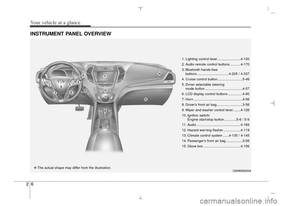
INSTRUMENT PANEL OVERVIEW
OANNIN2004❈The actual shape may differ from the illustration. 1. Lighting control lever ........................4-120
2. Audio remote control buttons ...........4-170
3. Bluetooth hands-free
buttons .................................4-205 / 4-337
4. Cruise control button ..........................5-46
5. Driver selectable steering mode button .......................................4-57
6. LCD display control buttons ...............4-80
7. Horn ...................................................4-56
8. Driver’s front air bag ...........................3-56
9. Wiper and washer control lever........4-126
10. Ignition switch/ Engine start/stop button.............5-6 / 5-9
11. Audio ..............................................4-169
12. Hazard warning flasher ..................4-119
13. Climate control system ......4-135 / 4-145
14. Passenger’s front air bag .................3-56
15. Glove box .......................................4-156
AN HMA 2.QXP 6/10/2015 11:21 AM Page 6
Page 29 of 763
Safety features of your vehicle
83
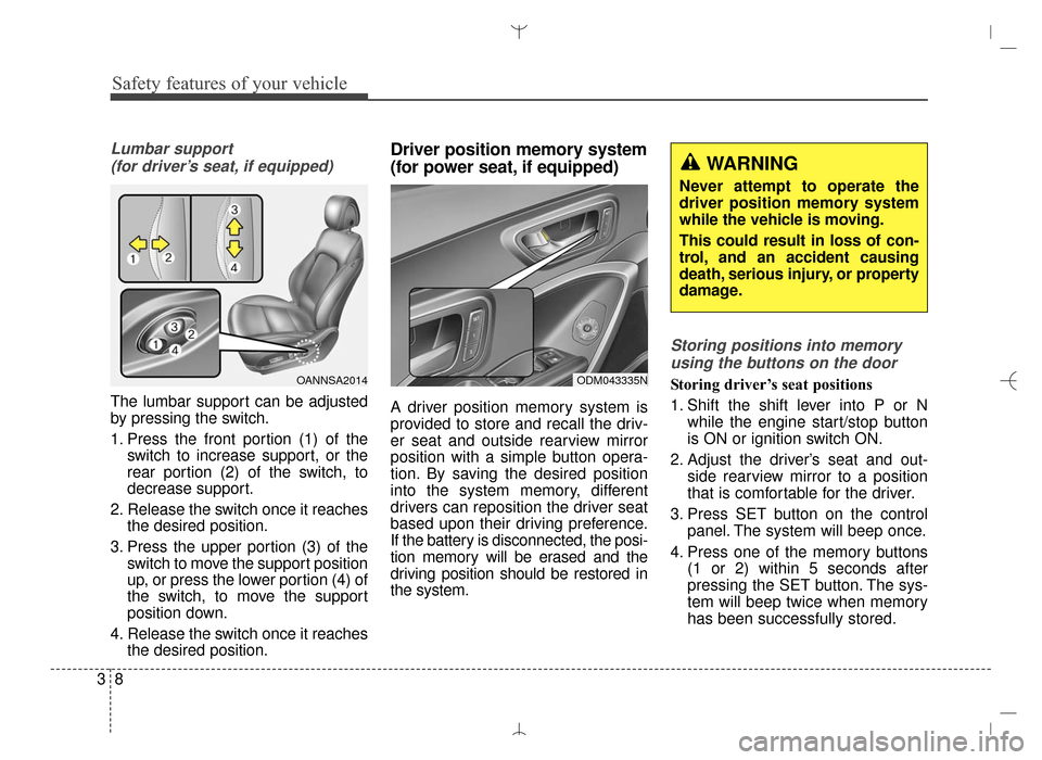
Lumbar support (for driver’s seat, if equipped)
The lumbar support can be adjusted
by pressing the switch.
1. Press the front portion (1) of the switch to increase support, or the
rear portion (2) of the switch, to
decrease support.
2. Release the switch once it reaches the desired position.
3. Press the upper portion (3) of the switch to move the support position
up, or press the lower portion (4) of
the switch, to move the support
position down.
4. Release the switch once it reaches the desired position.
Driver position memory system
(for power seat, if equipped)
A driver position memory system is
provided to store and recall the driv-
er seat and outside rearview mirror
position with a simple button opera-
tion. By saving the desired position
into the system memory, different
drivers can reposition the driver seat
based upon their driving preference.
If the battery is disconnected, the posi-
tion memory will be erased and the
driving position should be restored in
the system.
Storing positions into memory
using the buttons on the door
Storing driver’s seat positions
1. Shift the shift lever into P or N while the engine start/stop button
is ON or ignition switch ON.
2. Adjust the driver’s seat and out- side rearview mirror to a position
that is comfortable for the driver.
3. Press SET button on the control panel. The system will beep once.
4. Press one of the memory buttons (1 or 2) within 5 seconds after
pressing the SET button. The sys-
tem will beep twice when memory
has been successfully stored.OANNSA2014ODM043335N
WARNING
Never attempt to operate the
driver position memory system
while the vehicle is moving.
This could result in loss of con-
trol, and an accident causing
death, serious injury, or property
damage.
AN HMA 3.QXP 3/5/2015 3:09 PM Page 8
Page 30 of 763
39
Safety features of your vehicle
Recalling positions from memory
1. Shift the shift lever into P or Nwhile the engine start/stop button
is ON or ignition switch ON.
2. To recall the position in the memo- ry, press the desired memory but-
ton (1 or 2). The system will beep
once, then the driver’s seat will
automatically adjust to the stored
position.
Adjusting the control switch for the
driver’s seat while the system is
recalling the stored position will
cause the movement to stop and
move in the direction that the control
switch is moved.Easy access function (if equipped)
The system will move the driver's
seat automatically as follows:
Without smart key system
- It will move the driver’s seat rear-ward when the ignition key is
removed and front driver’s door is
opened.
- It will move the driver’s seat for- ward when the ignition key is
inserted.
With smart key system - It will move the driver’s seat rear-ward when the engine start/stop
button is changed to the OFF
position and front driver’s door is
opened.
- It will move the driver’s seat for- ward when the engine start/stop
button is changed to the ACC or
START position.
You can activate or deactivate this
feature. Refer to "User settings" in
section 4.
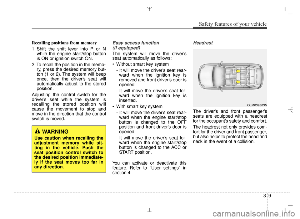
Headrest
The driver's and front passenger's
seats are equipped with a headrest
for the occupant's safety and comfort.
The headrest not only provides com-
fort for the driver and front passenger,
but also helps to protect the head and
neck in the event of a collision.
WARNING
Use caution when recalling the
adjustment memory while sit-
ting in the vehicle. Push the
seat position control switch to
the desired position immediate-
ly if the seat moves too far in
any direction.
OLM039303N
AN HMA 3.QXP 3/5/2015 3:09 PM Page 9
Page 65 of 763
Safety features of your vehicle
44
3
How does the air bag system
operate
Air bags are activated (able to
inflate if necessary) only when the
ignition switch is turned to the ON or
START position.
The appropriate air bags inflate instantly in the event of serious
frontal or side collision in order to
help protect the occupants from
serious physical injury.
There is no single speed at which the air bags will inflate.
Generally, air bags are designed to
inflate by the severity of a collision
and its direction. These two factors
determine whether the sensors
send out an electronic deployment/
inflation signal.
Air bag deployment depends on a number of factors including vehicle
speed, angles of impact and the
density and stiffness of the vehicles
or objects which your vehicle hits in
the collision. Though, factors are not
limited to those mentioned above. The front air bags will completely
inflate and deflate in an instant.
It is virtually impossible for you to
see the air bags inflate during an
accident.
It is much more likely that you will
simply see the deflated air bags
hanging out of their storage com-
partments after the collision.
In addition to inflating in serious side collisions, side and/or curtain
air bags will inflate if the sensing
system detects a rollover.
When a rollover is detected, side and/or curtain airbags will remain
inflated longer to help provide pro-
tection from ejection, especially
when used in conjunction with the
seat belts.
In order to help provide protection, the air bags must inflate rapidly. The
speed of air bag inflation is a con-
sequence of the extremely short
time in which to inflate the air bag
between the occupant and the vehi-
cle structures before the occupant
impacts those structures. This speed of inflation reduces the
risk of serious or life-threatening
injuries and is thus a necessary part
of air bag design.
However, air bag inflation can also
cause injuries which normally can
include facial abrasions, bruises and
broken bones because the inflation
speed also causes the air bags to
expand with a great deal of force.
There are even circumstances under which contact with the air
bag can cause fatal injuries, espe-
cially if the occupant is positioned
excessively close to the air bag.
WARNING
To avoid severe personal injuryor death caused by deploying
air bags in a collision, the driv-
er should sit as far back from
the steering wheel air bag as
possible (at least 10 inches
(250 mm) away). The front pas-
sengers should always move
their seats as far back as pos-
sible and sit back in their seat.
(Continued)
AN HMA 3.QXP 3/5/2015 3:09 PM Page 44
Page 69 of 763
Safety features of your vehicle
48
3
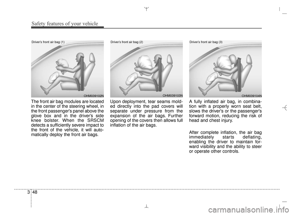
The front air bag modules are located
in the center of the steering wheel, in
the front passenger's panel above the
glove box and in the driver’s side
knee bolster. When the SRSCM
detects a sufficiently severe impact to
the front of the vehicle, it will auto-
matically deploy the front air bags. Upon deployment, tear seams mold-
ed directly into the pad covers will
separate under pressure from the
expansion of the air bags. Further
opening of the covers then allows full
inflation of the air bags.
A fully inflated air bag, in combina-
tion with a properly worn seat belt,
slows the driver's or the passenger's
forward motion, reducing the risk of
head and chest injury.
After complete inflation, the air bag
immediately starts deflating,
enabling the driver to maintain for-
ward visibility and the ability to steer
or operate other controls.
OHM039103N
Driver’s front air bag (2)
OHM039102N
Driver’s front air bag (1)
OHM039104N
Driver’s front air bag (3)
AN HMA 3.QXP 3/5/2015 3:09 PM Page 48