2016 Hyundai Santa Fe battery
[x] Cancel search: batteryPage 674 of 759
Maintenance
32
7
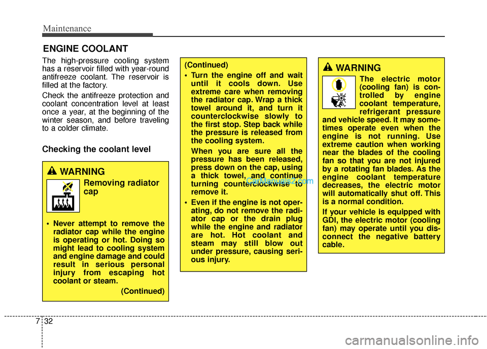
ENGINE COOLANT
The high-pressure cooling system
has a reservoir filled with year-round
antifreeze coolant. The reservoir is
filled at the factory.
Check the antifreeze protection and
coolant concentration level at least
once a year, at the beginning of the
winter season, and before traveling
to a colder climate.
Checking the coolant level
(Continued)
Turn the engine off and wait
until it cools down. Use
extreme care when removing
the radiator cap. Wrap a thick
towel around it, and turn it
counterclockwise slowly to
the first stop. Step back while
the pressure is released from
the cooling system.
When you are sure all the
pressure has been released,
press down on the cap, using
a thick towel, and continue
turning counterclockwise to
remove it.
Even if the engine is not oper- ating, do not remove the radi-
ator cap or the drain plug
while the engine and radiator
are hot. Hot coolant and
steam may still blow out
under pressure, causing seri-
ous injury.WARNING
The electric motor
(cooling fan) is con-
trolled by engine
coolant temperature,
refrigerant pressure
and vehicle speed. It may some-
times operate even when the
engine is not running. Use
extreme caution when working
near the blades of the cooling
fan so that you are not injured
by a rotating fan blades. As the
engine coolant temperature
decreases, the electric motor
will automatically shut off. This
is a normal condition.
If your vehicle is equipped with
GDI, the electric motor (cooling
fan) may operate until you dis-
connect the negative battery
cable.
WARNING
Removing radiator
cap
Never attempt to remove the radiator cap while the engine
is operating or hot. Doing so
might lead to cooling system
and engine damage and could
result in serious personal
injury from escaping hot
coolant or steam.
(Continued)
Page 687 of 759
745
Maintenance
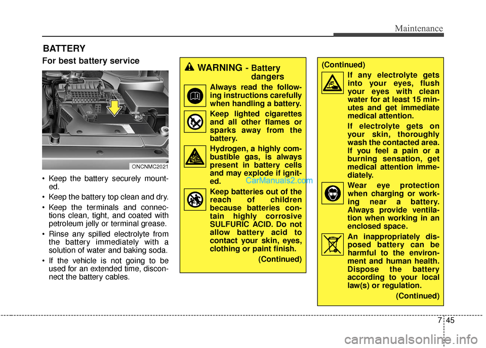
BATTERY
For best battery service
Keep the battery securely mount-ed.
Keep the battery top clean and dry.
Keep the terminals and connec- tions clean, tight, and coated with
petroleum jelly or terminal grease.
Rinse any spilled electrolyte from the battery immediately with a
solution of water and baking soda.
If the vehicle is not going to be used for an extended time, discon-
nect the battery cables.
WARNING- Battery dangers
Always read the follow-
ing instructions carefully
when handling a battery.
Keep lighted cigarettes and all other flames or
sparks away from the
battery.
Hydrogen, a highly com- bustible gas, is always
present in battery cells
and may explode if ignit-
ed.
Keep batteries out of the reach of children
because batteries con-
tain highly corrosive
SULFURIC ACID. Do not
allow battery acid to
contact your skin, eyes,
clothing or paint finish.
(Continued)
(Continued)If any electrolyte getsinto your eyes, flush
your eyes with clean
water for at least 15 min-
utes and get immediate
medical attention.
If electrolyte gets on your skin, thoroughly
wash the contacted area.
If you feel a pain or a
burning sensation, get
medical attention imme-
diately.
Wear eye protection when charging or work-
ing near a battery.
Always provide ventila-
tion when working in an
enclosed space.
An inappropriately dis- posed battery can be
harmful to the environ-
ment and human health.
Dispose the battery
according to your local
law(s) or regulation.
(Continued)
ONCNMC2021
Page 688 of 759
Maintenance
46
7
Battery recharging
Your vehicle has a maintenance-free,
calcium-based battery.
If the battery becomes discharged
in a short time (because, for exam-
ple, the headlights or interior lights
were left on while the vehicle was
not in use), recharge it by slow
charging (trickle) for 10 hours.
If the battery gradually discharges because of high electric load while
the vehicle is being used, recharge
it at 20-30A for two hours.(Continued)
When lifting a plastic-casedbattery, excessive pressure
on the case may cause battery
acid to leak, resulting in per-
sonal injury. Lift with a battery
carrier or with your hands on
opposite corners.
Never attempt to recharge the battery when the battery
cables are connected.
The electrical ignition system works with high voltage.
Never touch these compo-
nents with the engine running
or the ignition switched on.
Failure to follow the above
warnings can result in serious
bodily injury or death.CALIFORNIA PROPO-
SITION 65 WARNING
Battery posts, terminals, and
related accessories contain
lead and lead compounds,
chemicals known to the State of
California to cause cancer, birth
defects, and reproductive harm.
Batteries also contain other
chemicals known to the State of
California to cause cancer.
Wash hands after handling.
CAUTION
Always charge the battery fully to prevent battery casedamage in low temperaturearea.
If you connect unauthorized electronic devices to the bat-tery, the battery may dis-charge. Never use unautho-rized devices.
Page 689 of 759
747
Maintenance
Reset items
Items should be reset after the bat-
tery has been discharged or the bat-
tery has been disconnected.
Auto up/down window (See section 4)
Sunroof (See section 4)
Trip computer (See section 4)
Climate control system (See section 4)
Clock (See section 4)
Audio (See section 4)(Continued)
Disconnect the battery charg- er in the following order.
1. Turn off the battery charger main switch.
2. Unhook the negative clamp from the negative battery
terminal.
3. Unhook the positive clamp from the positive battery
terminal.
Before performing mainte- nance or recharging the bat-
tery, turn off all accessories
and stop the engine.
The negative battery cable must be removed first and
installed last when the battery
is disconnected.WARNING- Rechargingbattery
When recharging the battery,
observe the following precau-
tions:
The battery must be removed
from the vehicle and placed in
an area with good ventilation.
Do not allow cigarettes, sparks, or flame near the battery.
Watch the battery during charging, and stop or reduce
the charging rate if the battery
cells begin gassing (boiling)
violently or if the temperature
of the electrolyte of any cell
exceeds 120°F (49°C).
Wear eye protection when checking the battery during
charging.
(Continued)
Page 701 of 759
759
Maintenance
Occupant Distribution:Designated
seating positions.
Outward Facing Sidewall: The side
of a asymmetrical tire that has a par-
ticular side that faces outward when
mounted on a vehicle. The outward
facing sidewall bears white lettering
or bears manufacturer, brand, and/or
model name molding that is higher or
deeper than the same moldings on
the inner facing sidewall.
Passenger (P-Metric) Tire: A tire
used on passenger cars and some
light duty trucks and multipurpose
vehicles.
Ply: A layer of rubber-coated parallel
cords
Pneumatic tire: A mechanical
device made of rubber, chemicals,
fabric and steel or other materials,
that, when mounted on an automo-
tive wheel, provides the traction and
contains the gas or fluid that sustains
the load. Production options weight:
The
combined weight of installed regular
production options weighing over
5 lb. (2.3 kg) in excess of the stan-
dard items which they replace, not
previously considered in curb weight
or accessory weight, including heavy
duty brakes, ride levelers, roof rack,
heavy duty battery, and special trim.
Recommended Inflation Pressure:
Vehicle manufacturer's recommend-
ed tire inflation pressure and shown
on the tire placard.
Radial Ply Tire: A pneumatic tire in
which the ply cords that extend to the
beads are laid at 90 degrees to the
centerline of the tread.
Rim: A metal support for a tire and
upon which the tire beads are seated.
Sidewall: The portion of a tire
between the tread and the bead.
Speed Rating: An alphanumeric
code assigned to a tire indicating the
maximum speed at which a tire can
operate.
Traction: The friction between the
tire and the road surface. The
amount of grip provided. Tread:
The portion of a tire that
comes into contact with the road.
Treadwear Indicators: Narrow
bands, sometimes called "wear bars",
that show across the tread of a tire
when only 2/32 inch of tread remains.
UTQGS: Uniform Tire Quality
Grading Standards, a tire information
system that provides consumers with
ratings for a tire's traction, tempera-
ture and treadwear. Ratings are
determined by tire manufacturers
using government testing proce-
dures. The ratings are molded into
the sidewall of the tire.
Vehicle Capacity Weight: The num-
ber of designated seating positions
multiplied by 150 lbs. (68 kg) plus the
rated cargo and luggage load.
Vehicle Maximum Load on the Tire:
Load on an individual tire due to curb
and accessory weight plus maximum
occupant and cargo weight.
Vehicle Normal Load on the Tire:
Load on an individual tire that is
determined by distributing to each
axle its share of the curb weight,
accessory weight, and normal occu-
pant weight and dividing by 2.
Page 704 of 759
Maintenance
62
7
FUSES
A vehicle’s electrical system is pro-
tected from electrical overload dam-
age by fuses.
This vehicle has 2 fuse panels, one
located in the driver’s side panel bol-
ster, the other in the engine compart-
ment near the battery.
If any of your vehicle’s lights, acces-
sories, or controls do not work, check
the appropriate circuit fuse. If a fuse
has blown, the element inside the
fuse will be melted.
If the electrical system does not
work, first check the driver’s side
fuse panel.
Always replace a blown fuse with
one of the same rating.
Before replacing an open fuse, dis-
connect the negative battery cable.
If the replacement fuse blows, this
indicates an electrical problem. Avoid
using the system involved and imme-
diately consult an authorized
HYUNDAI dealer.
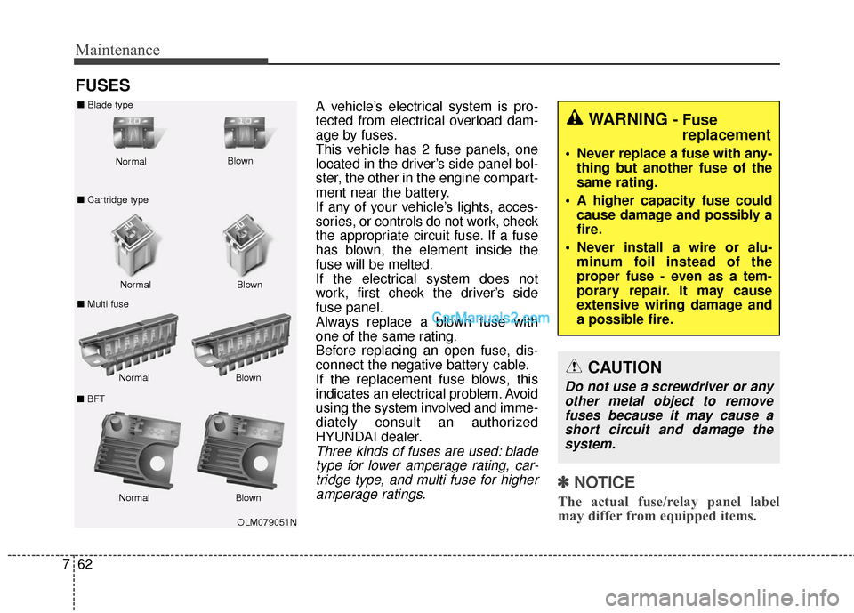
Three kinds of fuses are used: blade
type for lower amperage rating, car-tridge type, and multi fuse for higheramperage ratings.
✽ ✽ NOTICE
The actual fuse/relay panel label
may differ from equipped items.
OLM079051N
Normal
Normal
■
Blade type
■ Cartridge type
■ Multi fuse Blown
Blown
Normal Blown
Normal Blown
WARNING - Fuse
replacement
Never replace a fuse with any-
thing but another fuse of the
same rating.
A higher capacity fuse could cause damage and possibly a
fire.
Never install a wire or alu- minum foil instead of the
proper fuse - even as a tem-
porary repair. It may cause
extensive wiring damage and
a possible fire.
CAUTION
Do not use a screwdriver or anyother metal object to removefuses because it may cause ashort circuit and damage thesystem.■ BFT
Page 707 of 759
765
Maintenance
3. Check the removed fuse; replace itif it is blown. To remove or insert
the fuse, use the fuse puller in the
engine compartment fuse panel.
4. Push in a new fuse of the same rating, and make sure it fits tightly
in the clips. If it fits loosely, consult
an authorized HYUNDAI dealer.Multi fuse
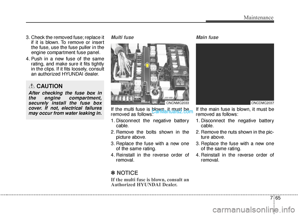
If the multi fuse is blown, it must be
removed as follows:
1. Disconnect the negative batterycable.
2. Remove the bolts shown in the picture above.
3. Replace the fuse with a new one of the same rating.
4. Reinstall in the reverse order of removal.
✽ ✽NOTICE
If the multi fuse is blown, consult an
Authorized HYUNDAI Dealer.
Main fuse
If the main fuse is blown, it must be
removed as follows:
1. Disconnect the negative battery
cable.
2. Remove the nuts shown in the pic- ture above.
3. Replace the fuse with a new one of the same rating.
4. Reinstall in the reverse order of removal.
ONCNMC2033ONCDMC2037
CAUTION
After checking the fuse box inthe engine compartment,securely install the fuse boxcover. If not, electrical failuresmay occur from water leaking in.
Page 715 of 759

773
Maintenance
DescriptionFuse ratingProtected Component
FUSE
P/TAIL GATE30APower Tail Gate Module
IDB15AIDB Module
4WD20A4WD ECM
AMS10ABattery Sensor
AMS (WIPER)10ABCM, PCM
WIPER FRT25AWiper LO Relay, Front Wiper Motor
B/UP LAMP10AA/T - Rear Combination Lamp (IN) LH/RH, Electro Chromic Mirror, Audio, A/V & Navigation
Head Unit
ABS37.5AESC Module
SENSOR57.5APCM
TCU15AA/T : Transaxle Range Switch
F/PUMP15AFuel Pump Relay
ECU 115APCM
ECU 210AIDB Module
SENSOR 310AFuel Pump Relay
IGN COIL20ACondenser, Ignition Coil #1/#2/#3/#4
SENSOR 210APurge Control Solenoid Valve, Variable Intake Solenoid Valve(G4KJ), Oil Control Valve #1/#2
SENSOR 115AOxygen sensor(#1/#2/#3/#4), PCM, Oxygen Sensor(Down), E/R Fuse & Relay Box (Cooling
Fan Relay)
B/A HORN10ABurgl Aralarm Horn Relay