Page 507 of 550
747
Maintenance
3. Check the removed fuse; replace it if itis blown. To remove or insert the fuse,
use the fuse puller in the engine com-
partment fuse panel.
4. Push in a new fuse of the same rating, and make sure it fits tightly in the clips.
If it fits loosely, we recommend that
you consult a HYUNDAI authorised
repairer.
Main fuseIf the main fuse is blown, it must be
removed as follows:
1. Turn off the engine.
2. Disconnect the negative battery cable. 3. Remove the nuts shown in the picture
above.
4. Replace the fuse with a new one of the same rating.
5. Reinstall in the reverse order of removal.
CAUTION
After checking the fuse box in theengine compartment, securelyinstall the fuse box cover. If not,electrical failures may occur fromwater leaking in.
OLM079052ROEL070305R
■ Type A■Type B
EL(FL) UK 7.QXP 3/4/2015 9:06 PM Page 47
Page 508 of 550
Maintenance48
7Multi fuseIf the multi fuse is blown, it must be
removed as follows:
1. Turn off the engine.
2. Disconnect the negative battery cable.
3. Remove the fuse panel on the right
side in the engine compartment.
4. Remove the nuts shown in the picture above.
5. Replace the fuse with a new one of the same rating.
6. Reinstall in the reverse order of removal.
✽ ✽NOTICEIf the main fuse is blown, we recom-
mend that you consult a HYUNDAI
authorised repairer.
OLM079025
EL(FL) UK 7.QXP 3/4/2015 9:06 PM Page 48
Page 509 of 550
749
Maintenance
Engine compartment
OLM079026R/OLM079053R/OLM079027/OEL070306R/OLM079028
Fuse/Relay panel descriptionInside the fuse/relay box covers, you can find the fuse/relay label describing fuse/relay name and capacity.
Diesel only
Driver’s side panel Main fuse
■
Type A■Type B
✽
✽
NOTICENot all fuse panel descriptions in this manual may be applicable to your\
vehicle. It is accurate at the time of printing. When you
inspect the fuse box on your vehicle, refer to the fuse box label.
EL(FL) UK 7.QXP 3/4/2015 9:07 PM Page 49
Page 513 of 550

753
Maintenance
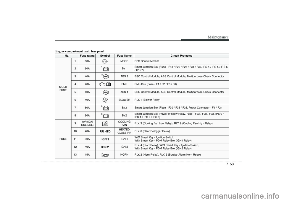
Engine compartment main fuse panel
No.
Fuse rating
Symbol
Fuse Name
Circuit Protected
MULTIFUSE
1
80A
MDPS
EPS Control Module
2
60A
B+1
Smart Junction Box (Fuse - F13 / F20 / F26 / F31 / F37, IPS 4 / IPS 5 / IPS 6
/ IPS 7)
3
40A
ABS 2
ESC Control Module, ABS Control Module, Multipurpose Check Connector
4
40A
EMS
EMS Box (Fuse - F1 / F2 / F3 / F6)
5
40A
ABS 1
ESC Control Module, ABS Control Module, Multipurpose Check Connector
6
40A
BLOWER
RLY. 1 (Blower Relay)
7
60A
B+3
Smart Junction Box (Fuse - F30 / F35 / F36, Power Connector - F1 / F2)
8
60A
B+2
Smart Junction Box (Power Window Relay, Fuse - F23 / F28 / F33, IPS 0 /
IPS 1 / IPS 2 / IPS 3)
FUSE
9
40A(50A)
GSL(DSL)
COOLING FA N
RLY. 3 (Cooling Fan Low Relay), RLY. 9 (Cooling Fan High Relay)
10
40A
HEATED
GLASS RR
RLY. 6 (Rear Defogger Relay)
11
30A
IGN 1
W/O Smart Key - Ignition Switch,
With Smart Key - PDM Relay Box (IGN1 Relay)
12
40A
IGN 2
RLY. 4 (Start Relay), W/O Smart Key - Ignition Switch,
With Smart Key - PDM Relay Box (IGN2 Relay)
13
15A
HORN
RLY. 2 (Horn Relay), RLY. 5 (Burglar Alarm Horn Relay)
EL(FL) UK 7.QXP 3/4/2015 9:07 PM Page 53
Page 515 of 550
755
Maintenance
Engine compartment sub fuse panel (Disel Engine)No.
Fuse rating
Fuse Symbol
Circuit Protected
Relay Symbol
Relay Type
1
50A
PTC Heater Relay #1
MICRO PLUG
2
50A
PTC Heater Relay #2
MICRO PLUG
3
50A
PTC Heater Relay #3
MICRO PLUG
4
30A
Fuel Filter Heater Relay
MICRO PLUG
5
80A
Glow Relay Unit
-
-
EL(FL) UK 7.QXP 3/4/2015 9:07 PM Page 55
Page 519 of 550

759
Maintenance
Turn signal light/Position lightTurn signal light
1. Turn off the engine and open the bon-net.
2. Remove the socket from the assembly by turning the socket counterclockwise
until the tabs on the socket align with
the slots on the assembly.
3. Remove the bulb from the socket by pressing it in and rotating it counter-
clockwise until the tabs on the bulb
align with the slots in the socket. Pull
the bulb out of the socket.
4. Insert a new bulb by inserting it into the socket and rotating it until it locks
into place.
5. Install the socket in the assembly by aligning the tabs on the socket with the
slots in the assembly. Push the socket
into the assembly and turn the socket
clockwise.
Position light
If the light bulb does not operate, we rec-
ommend that the system be checked by
a HYUNDAI authorised repairer.
(Continued)
If a bulb becomes damaged or cracked, replace it immediately
and carefully dispose of it.
Wear eye protection when chang- ing a bulb. Allow the bulb to cool
down before handling it.
WARNING
- Halogen bulbs
Halogen bulbs contain pressur-ized gas that will produce flying
pieces of glass if broken.
Always handle them carefully, and avoid scratches and abra-
sions. If the bulbs are lit, avoid
contact with liquids. Never touch
the glass with bare hands.
Residual oil may cause the bulb
to overheat and burst when lit. A
bulb should be operated only
when installed in a headlight.
(Continued)
OHD076046
EL(FL) UK 7.QXP 3/4/2015 9:07 PM Page 59
Page 531 of 550

771
Maintenance
Waxing
Wax the vehicle when water will no
longer bead on the paint.
Always wash and dry the vehicle before
waxing. Use a good quality liquid or
paste wax, and follow the manufacturer’s
instructions. Wax all metal trim to protect
it and to maintain its luster.
Removing oil, tar, and similar materials
with a spot remover will usually strip the
wax from the finish. Be sure to re-wax
these areas even if the rest of the vehicle
does not yet need waxing.
Finish damage repair Deep scratches or stone chips in the
painted surface must be repaired
promptly. Exposed metal will quickly rust
and may develop into a major repair
expense.✽ ✽NOTICEIf your vehicle is damaged and requires
any metal repair or replacement, be sure
the body shop applies anti-corrosion
materials to the parts repaired or
replaced.
CAUTION
Wiping dust or dirt off the body
with a dry cloth will scratch thefinish.
Do not use steel wool, abrasive cleaners, or strong detergentscontaining highly alkaline orcaustic agents on chrome-platedor anodized aluminium parts. This may result in damage to the pro-tective coating and cause discol- oration or paint deterioration.
CAUTION
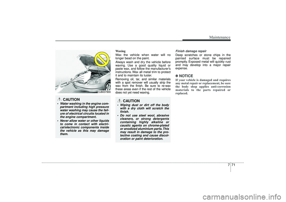
Water washing in the engine com- partment including high pressurewater washing may cause the fail-ure of electrical circuits located inthe engine compartment.
Never allow water or other liquids to come in contact with electri-cal/electronic components insidethe vehicle as this may damage them.
OJB037800
EL(FL) UK 7.QXP 3/4/2015 9:08 PM Page 71
Page 536 of 550

Maintenance76
7EMISSION CONTROL SYSTEMThe emission control system of your
vehicle is covered by a written limited
warranty. Please see the warranty infor-
mation contained in the Service Passport
in your vehicle.
Your vehicle is equipped with an emis-
sion control system to meet all emission
regulations.
There are three emission control sys-
tems which are as follows.
(1) Crankcase emission control system
(2) Evaporative emission control system
(3) Exhaust emission control system
In order to assure the proper function of
the emission control systems, it is rec-
ommended that you have your car
inspected and maintained by a
HYUNDAI authorised repairer in accor-
dance with the maintenance schedule. Caution for the Inspection and
Maintenance Test (With Electronic
Stability Control (ESC) system)
To prevent the vehicle from misfir-
ing during dynamometer testing,
turn the Electronic Stability Control
(ESC) system off by pressing the
ESC switch.
After dynamometer testing is com- pleted, turn the ESC system back on
by pressing the ESC switch again.
1. Crankcase emission control systemThe positive crankcase ventilation sys-
tem is employed to prevent air pollution
caused by blow-by gases being emitted
from the crankcase. This system supplies
fresh filtered air to the crankcase through
the air intake hose. Inside the crankcase,
the fresh air mixes with blow-by gases,
which then pass through the PCV valve
into the induction system.
2. Evaporative emission controlSystemThe Evaporative Emission Control
System is designed to prevent fuel
vapours from escaping into the atmos-
phere.CanisterFuel vapours generated inside the fuel
tank are absorbed and stored in the
onboard canister. When the engine is
running, the fuel vapours absorbed in the
canister are drawn into the surge tank
through the purge control solenoid valve.Purge Control Solenoid Valve (PCSV)The purge control solenoid valve is con-
trolled by the Engine Control Module
(ECM); when the engine coolant temper-
ature is low during idling, the PCSV clos-
es so that evaporated fuel is not taken
into the engine. After the engine warms-
up during ordinary driving, the PCSV
opens to introduce evaporated fuel to the
engine.
EL(FL) UK 7.QXP 3/4/2015 9:08 PM Page 76