Page 456 of 498
761
Maintenance
Fuse NameSymbolFuse ratingProtected Component
P/WDW RH25AP/WDW RH Relay, Driver Safety Power Window Module(RHD)
PDM 27.5ASmart Key Control Module, Start Stop Button Switch
FOG LIGHT RR10AICM Relay Box(Rear Fog Light Relay)
WIPER FRT25AICM Relay Box(Rain Sensor Relay), Multifunction Switch, E/R Fuse & Relay Box(RLY.2),
Wiper Motor
MODULE 57.5ACluster Ionizer, Rain Sensor, Sunroof
SPARE7.5A-
AMP25AAMP
PDM 125ASmart Key Control Module
SPARE20A-
A/CON7.5AE/R Fuse & Relay Box(RLY.10), A/C Control Module
MEMORY10ABCM, Auto Light & Photo Sensor, Instrument Cluster, Data Link Connector,
Smart Jucntion Box Upgrade Connector, A/C Control Module, Digital Clock
P/WDW LH25AP/WDW LH Relay, Driver Safety Power Window Module(LHD)
DR LOCK20ADoor Lock Relay, Door Unlock Relay
P/SEAT DRV30ADriver Seat Manual Switch
Page 465 of 498

Maintenance
70 7
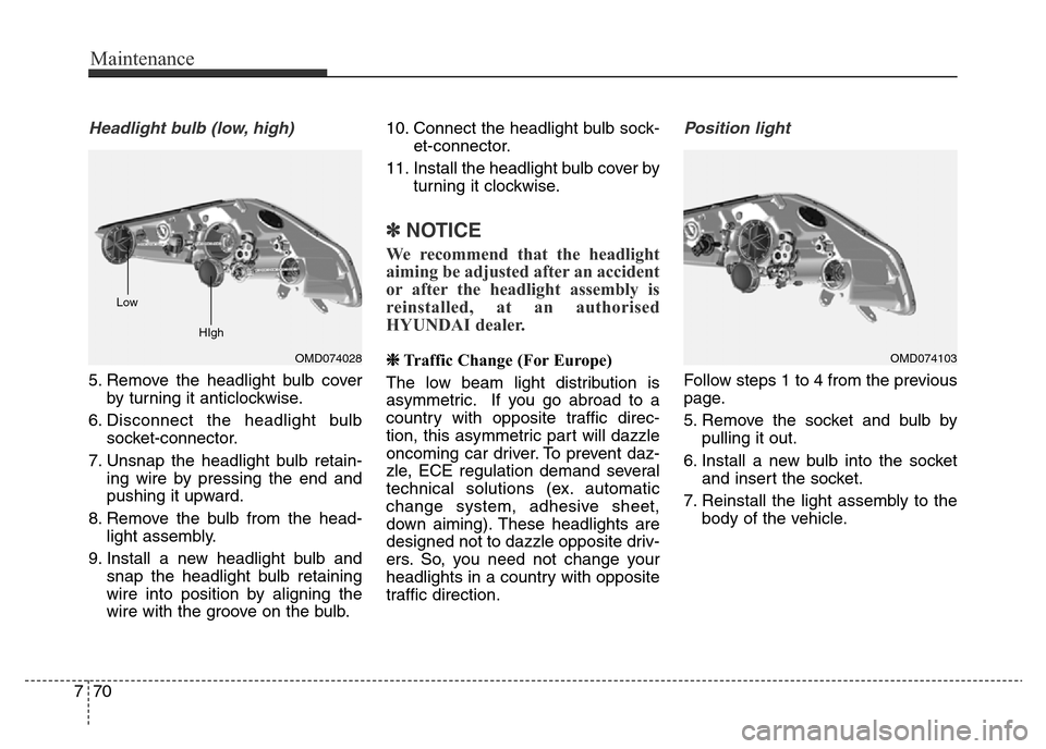
Headlight bulb (low, high)
5. Remove the headlight bulb cover
by turning it anticlockwise.
6. Disconnect the headlight bulb
socket-connector.
7. Unsnap the headlight bulb retain-
ing wire by pressing the end and
pushing it upward.
8. Remove the bulb from the head-
light assembly.
9. Install a new headlight bulb and
snap the headlight bulb retaining
wire into position by aligning the
wire with the groove on the bulb.10. Connect the headlight bulb sock-
et-connector.
11. Install the headlight bulb cover by
turning it clockwise.
✽NOTICE
We recommend that the headlight
aiming be adjusted after an accident
or after the headlight assembly is
reinstalled, at an authorised
HYUNDAI dealer.
❈Traffic Change (For Europe)
The low beam light distribution is
asymmetric. If you go abroad to a
country with opposite traffic direc-
tion, this asymmetric part will dazzle
oncoming car driver. To prevent daz-
zle, ECE regulation demand several
technical solutions (ex. automatic
change system, adhesive sheet,
down aiming). These headlights are
designed not to dazzle opposite driv-
ers. So, you need not change your
headlights in a country with opposite
traffic direction.
Position light
Follow steps 1 to 4 from the previous
page.
5. Remove the socket and bulb by
pulling it out.
6. Install a new bulb into the socket
and insert the socket.
7. Reinstall the light assembly to the
body of the vehicle.
OMD074103OMD074028 Low
HIgh
Page 466 of 498
771
Maintenance
Front turn signal bulb
Follow steps 1 to 4 from the previous
page.
5. Remove the socket from the
assembly by turning the socket
anticlockwise until the tabs on the
socket align with the slots on the
assembly.
6. Remove the bulb from the socket
by pressing it in and rotating it
anticlockwise until the tabs on the
bulb align with the slots in the
socket. Pull the bulb out of the
socket.7. Insert a new bulb by inserting it
into the socket and rotating it until
it locks into place.
8. Install the socket in the assembly
by aligning the tabs on the socket
with the slots in the assembly.
Push the socket into the assembly
and turn the socket clockwise.
9. Reinstall the light assembly to the
body of the vehicle.
Front fog light and Dedicated
light (if equipped)
1. Disconnect the negative battery
cable.
2. Remove the screws under the
front bumper.
3. Disconnect the power connector
from the socket.
OMD074104
OMD074029 Turn signal
Page 467 of 498

Maintenance
72 7
Front fog light (if equipped)
4. Remove the bulb-socket from the
housing by turning the socket anti-
clockwise until the tabs on the
socket align with the slots on the
housing.
5. Install the new bulb-socket into the
housing by aligning the tabs on
the socket with the slots in the
housing. Push the socket into the
housing and turn the socket clock-
wise.
6. Connect the power connector to
the socket.Dedicated light (if equipped)
Follow steps 1 to 3 from the previous
page.
4. Remove the socket from the
assembly by turning the socket
anticlockwise until the tabs on the
socket align with the slots on the
assembly.
5. Remove the bulb by pulling it out.
6. Insert a new bulb by inserting it
into the socket.
7. Install the socket in the assembly
by aligning the tabs on the socket
with the slots in the assembly.
Push the socket into the assembly
and turn the socket clockwise.Headlight and front fog light
aiming
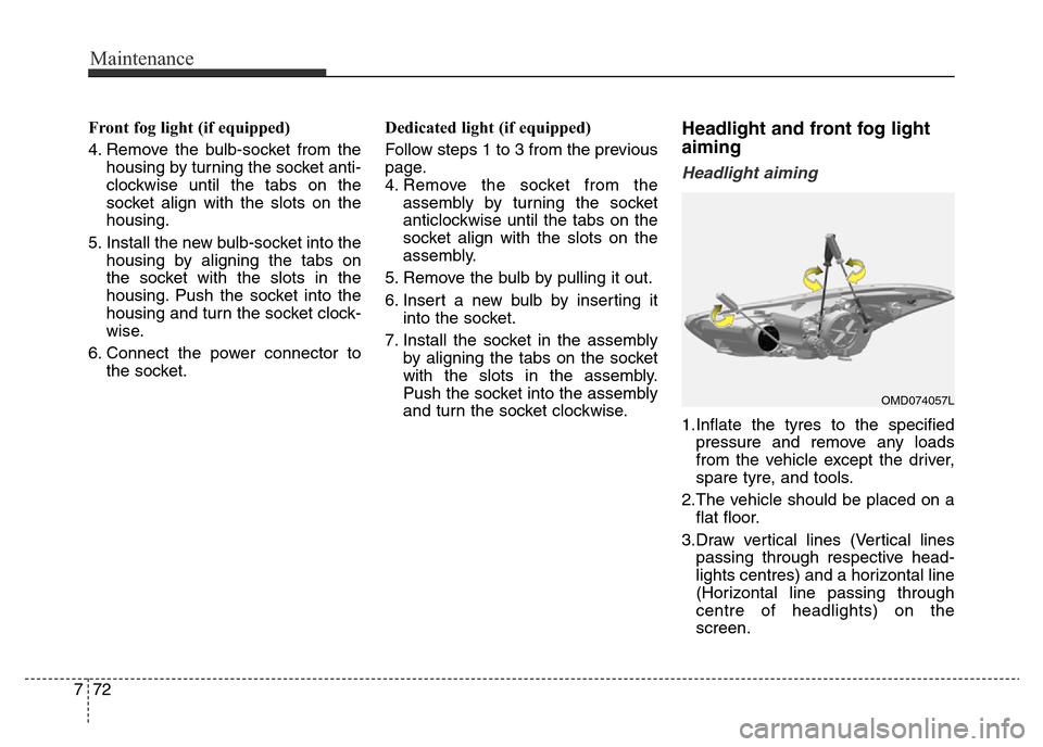
Headlight aiming
1.Inflate the tyres to the specified
pressure and remove any loads
from the vehicle except the driver,
spare tyre, and tools.
2.The vehicle should be placed on a
flat floor.
3.Draw vertical lines (Vertical lines
passing through respective head-
lights centres) and a horizontal line
(Horizontal line passing through
centre of headlights) on the
screen.
OMD074057L
Page 468 of 498
773
Maintenance
4.With the headlight and battery in
normal condition, aim the head-
lights so the brightest portion falls
on the horizontal and vertical lines.
5.To aim the low beam left or right,
turn the driver clockwise or anti-
clockwise. To aim the low beam up
or down, turn the driver clockwise
or anticlockwise.
To aim the high beam up or down,
turn the driver clockwise or anti-
clockwise.Front fog light aiming
The front fog light can be aimed as
the same manner of the headlights
aiming.
With the front fog lights and battery
normal condition, aim the front fog
lights.
To aim the front fog light up or down,
turn the driver clockwise or anticlock-
wise.
OMD074061L
Page 473 of 498
Maintenance
78 7
3. Loosen the assembly retaining
nuts.4. Remove the rear combination light
assembly from the body of the
vehicle.
Stop/Tail light and turn signal light
5. Remove the socket from the
assembly by turning the socket
anticlockwise until the tabs on the
socket align with the slots on the
assembly.
6. Remove the bulb from the socket
by pressing it in and rotating it
anticlockwise until the tabs on the
bulb align with the slots in the
socket. Pull the bulb out of the
socket.
7. Insert a new bulb by inserting it
into the socket and rotating it until
it locks into place.
OMD070033
OMD070034
OMD074080
Page 474 of 498
779
Maintenance
8. Install the socket in the assembly
by aligning the tabs on the socket
with the slots in the assembly.
Push the socket into the assembly
and turn the socket clockwise.Tail light
5. Remove the socket from the
assembly by turning the socket
anticlockwise until the tabs on the
socket align with the slots on the
assembly.
6. Remove the bulb by pulling it out.
7. Inset a new bulb by insetring it into
the socket.
8. Install the socket in the assembly
by aligning the tabs on the socket
with the slots in the assembly.
Push the socket into the assembly
and turn the socket clockwise.Inboard light
1.Open the boot.
2.Loosen the retaining screw of the
boot lid cover and then remove the
cover.
OMD070037
OMD070038
Page 475 of 498
Maintenance
80 7
3.Disconnect the connector and then
remove the nuts by turning the nuts
anticlockwise.
Reverse light
To remove the Rear combination
light assembly, see Outboard Light
previously in this section.
1. Take the light assembly out.
2. Remove the socket from the
assembly by turning the socket anti-
clockwise until the tabs on the sock-
et align with the slots on the assem-
bly.
3. Remove the bulb by pulling it out.
4. Insert a new bulb by inserting it
into the socket.
OMD074040
OMD074108 (If equipped with rear fog)