2016 HONDA ODYSSEY ignition
[x] Cancel search: ignitionPage 526 of 565
525
Handling the Unexpected
Shift Lever Does Not Move
Follow the procedure below if you cannot move the shift lever out of the (P
position.
1.Set the parking brake.
2. Remove the key from th e ignition switch.
2. Remove the built-in key from the smart
entry remote.
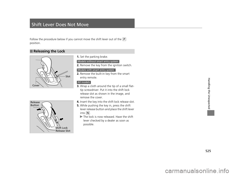
3. Wrap a cloth around the tip of a small flat-
tip screwdriver. Put it into the shift lock
release slot as shown in the image, and
remove the cover.
4. Insert the key into the shift lock release slot.
5. While pushing the key in, press the shift
lever release button and place the shift lever
into
(N.
u The lock is now released. Have the shift
lever checked by a de aler as soon as
possible.
■Releasing the Lock
Slot
Cover
Models without smart entry system
Models with smart entry system
All models
Release
Button
Shift Lock
Release Slot
16 US ODYSSEY-31TK86500.book 525 ページ 2015年6月24日 水曜日 午後3時0分
Page 534 of 565
533Continued
Handling the Unexpected
Fuses
Fuse Locations
If any electrical devices are not working,
turn the ignition switch to LOCK
(0*1 and
check to see if any appl icable fuse is blown.
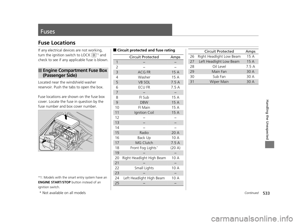
Located near the windshield washer
reservoir. Push the tabs to open the box.
Fuse locations are shown on the fuse box
cover. Locate the fuse in question by the
fuse number and box cover number.
*1: Models with the smart entry system have an
ENGINE START/STOP button instead of an
ignition switch.
■Engine Compartment Fuse Box
(Passenger Side)
■Circuit protected and fuse rating
Circuit ProtectedAmps
1−−
2− −
3ACG FR15 A
4Washer 15 A
5VB SOL7.5 A
6 ECU FR 7.5 A
7−−
8FI Sub 15A
9DBW15 A
10 FI Main 15 A
11Ignition Coil15 A
12− −
13−−
14− −
15Radio20 A
16 Back Up 10 A
17MG Clutch7.5 A
18 Front Fog Lights*(20 A)
19−−
20 Right Headlight High Beam 10 A
21−−
22 Small Lights 10 A
23−−
24 Left Headlight High Beam 10 A
25−−
26 Right Headlight Low Beam 15 A
27Left Headlight Low Beam15 A
28 Oil Level 7.5 A
29Main Fan30 A
30 Sub Fan 30 A
31Wiper Main30 A
Circuit ProtectedAmps
* Not available on all models
16 US ODYSSEY-31TK86500.book 533 ページ 2015年6月24日 水曜日 午後3時0分
Page 539 of 565
538
uuFuses uInspecting and Changing Fuses
Handling the Unexpected
Inspecting and Changing Fuses
1. Turn the ignition switch to LOCK (0*1. Turn
headlights and all accessories off.
2. Remove the fuse box cover.
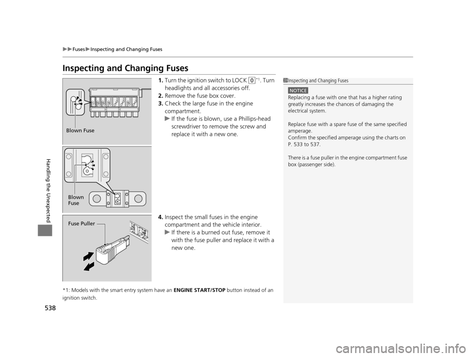
3. Check the large fuse in the engine
compartment.
u If the fuse is blown, use a Phillips-head
screwdriver to remo ve the screw and
replace it with a new one.
4. Inspect the small fuses in the engine
compartment and the vehicle interior.
u If there is a burned out fuse, remove it
with the fuse puller and replace it with a
new one.
*1: Models with the smart entry system have an ENGINE START/STOP button instead of an
ignition switch.
1 Inspecting and Changing Fuses
NOTICE
Replacing a fuse with on e that has a higher rating
greatly increases the chances of damaging the
electrical system.
Replace fuse with a spare fuse of the same specified
amperage.
Confirm the specified amperage using the charts on
P. 533 to 537.
There is a fuse puller in the engine compartment fuse
box (passenger side).
Blown Fuse
Blown
Fuse
Fuse Puller
16 US ODYSSEY-31TK86500.book 538 ページ 2015年6月24日 水曜日 午後3時0分
Page 548 of 565
547Continued
Information
Emissions Testing
Testing of Readiness Codes
Your vehicle uses “readiness codes,” as part of its onboard self diagnostic system.
Some states refer to these codes during testing to see if your vehicle's emissions
components are working properly.
The codes may not be read if you go thro ugh the testing just after the battery has
gone dead or been disconnected.
To check if they are set, tu rn the ignition switch to ON
(w*1, without starting the
engine. The malfunction indicator lamp will co me on for several seconds. If it then
goes off, the readiness codes are set. If it blinks five times, the readiness codes are
not set.
If you are required to have your vehicle te sted before the readiness codes are ready,
prepare the vehicle for retest ing by doing the following:
1. Fill the gas tank to approximately 3/4 full.
2. Park the vehicle and leave the engi ne off for six hours or more.
3. Make sure the ambient temperature is between 40°F and 95°F (4°C and 35°C).
4. Start the engine without touching the ac celerator pedal, and let it idle for 20
seconds.
5. Keep the vehicle in
(P. Increase the engine speed to 2,000 rpm, and hold it there
until the temperature gauge rises to at least 1/4 of the scale (about three
minutes).
6. Let the engine idle with your foot off the accelerator for 20 seconds.
*1: Models with the smart entry system have an ENGINE START/STOP button instead of an
ignition switch.
1 Testing of Readiness Codes
The readiness codes are erased when the battery is
disconnected, and set again only after several days of
driving under a variety of conditions.
If a testing facility determines that the readiness
codes are not set, you may be requested to return at
a later date to complete the test.
If the testing facility determines the readiness codes
are still not set, see a dealer.
16 US ODYSSEY-31TK86500.book 547 ページ 2015年6月24日 水曜日 午後3時0分
Page 557 of 565
556
Index
Fuses.......................................................... 533
Inspecting and Changing ......................... 538
Locations ................. 533, 534, 535, 536, 537
G
Gasoline (Fuel)
Economy ................................................. 449
Gauge ....................................................... 92
Information ............................................. 446
Instant Fuel Economy ........................... 94, 97
Low Fuel Indicator ..................................... 73
Refueling ................................................. 446
Gauges ......................................................... 92
Gear Shift Lever Positions Automatic Transmission ........................... 413
Glass (care) ........................................ 505, 508
Glove Box .................................................. 178
Grocery Bag Hooks ................................... 187
H
Halogen Bulbs................................... 475, 479
Handling the Unexpected ........................ 509
HandsFreeLink® (HFL)....................... 327, 360
Auto Answer ................................... 342, 374
Automatic Import of Ce llular Phonebook and
Call History .................................... 344, 376
Automatic Transferring .................... 342, 374
Displaying e-mail messages ...................... 389
Displaying Text Me ssages................. 356, 388 HFL Buttons..................................... 327, 360
HFL Menus ...................................... 329, 362
HFL Status Display ........................... 328, 361
Limitations for Manual Operation .... 328, 361
Making a Call .................................. 348, 380
Options During a Call ...................... 354, 385
Phone Setup.................................... 334, 366
Receiving a Call ............................... 353, 384
Receiving a Text Message ........................ 355
Receiving a Text/E-mail Message.............. 386
Ring Tone........................................ 343, 375
Selecting a Mail Account ......................... 387
Speed Dial ....................................... 345, 377
To Create a Security PIN .................. 341, 373
To Set Up a Text Message Options .......... 339
To Set Up a Text/E-mail Message
Options ................................................. 371
Use Contact Photo .................................. 375
Hazard Warning Button .............................. 4
Head Restraints ........................................ 164
Headlights ................................................. 147
Aiming .................................................... 475
Automatic Operation............................... 148
Dimming ......................................... 147, 150
Operating................................................ 147
Heaters (Seat) ........................................... 189
Heating and Cooling System ................... 194
Cooling ................................................... 196
Defrosting the Windshield and Windows ............................................... 196
Dust and Pollen Filter............................... 504 Heating................................................... 195
HFL (HandsFreeLink ®) ...................... 327, 360
High Beam Indicator .................................. 77
HondaVAC
TM............................................. 191
I
Identification Numbers Engine and Transmission ......................... 544
Vehicle Identification............................... 544
Ignition Switch ......................................... 142
Illumination Control ................................ 153
Knob ...................................................... 153
Immobilizer System .................................. 135
Indicator ................................................... 78
Indicators .................................................... 70
Anti-lock Brake System (ABS) .................... 73
Blind spot information (BSI) ....................... 83
Brake System (Amber) ............................... 70
Charging System............................... 72, 528
CRUISE CONTROL ............................. 82, 416
CRUISE MAIN.................................... 82, 415
Daytime Running Lights ............................ 75
Door and Tailgate Open ...................... 29, 75
Fog Light .................................................. 78
Forward Collision Wa rning (FCW) ............. 80
Fuel Economy ........................................... 82
Hazard Warning........................................ 77
High Beam ................................................ 77
Immobilizer System ................................... 78
Lane Departure Warning (LDW) ................ 81
16 US ODYSSEY-31TK86500.book 556 ページ 2015年6月24日 水曜日 午後3時0分