2016 FORD FUSION (AMERICAS) lock
[x] Cancel search: lockPage 262 of 518

Vertical Aim Adjustment Procedure
1. Park the vehicle directly in front of a
wall or screen on a level surface,
approximately 25 feet (7.6 meters)
away.
2. Measure the height of the headlamp bulb center from the ground and mark
an 8 foot (2.4 meter) horizontal
reference line on the vertical wall or
screen at this height.
Note: To see a clearer light pattern for
adjusting, you may want to block the light
from one headlamp while adjusting the
other.
3. Turn on the low beam headlamps to illuminate the wall or screen and open
the hood. 4. On the wall or screen you will observe
a flat zone of high intensity light
located at the top of the right hand
portion of the beam pattern. If the top
edge of the high intensity light zone is
not at the horizontal reference line, the
headlamp will need to be adjusted. 5. Locate the vertical adjuster on each
headlamp. Using a Phillips #2
screwdriver, turn the adjuster either
clockwise or counterclockwise in order
to adjust the vertical aim of the
headlamp. The horizontal edge of the
brighter light should touch the
horizontal reference line.
6. Close the hood and turn off the lamps.
Horizontal Aim Adjustment
Horizontal aim is not required for this
vehicle and is not adjustable.
259
Fusion/Mondeo (CC7) Canada/United States of America, enUSA, First Printing MaintenanceE142465 E145594
Page 263 of 518

REMOVING A HEADLAMP
Note:
To remove push pins, use a
flat-bladed screwdriver to pull up the center
release pin.
1. Make sure the headlamp control is in the off position and open the hood.
2. Remove the six push pins securing the
front fascia to the front trim cover.
3. Remove the three bumper cover upper
screws using a flat-bladed screwdriver.
4. Remove the push pin at the inboard side of the headlamp you are servicing. 5. Remove the two screws securing the
headlamp using a flat-bladed
screwdriver. 6.
Remove the lower three wheel housing
fasteners by turning them
counterclockwise.
260
Fusion/Mondeo (CC7) Canada/United States of America, enUSA, First Printing MaintenanceE159693 E159694 E159695
Page 264 of 518

7.
Remove the two outmost front bumper
cover lower fasteners, only on the side
of the headlamp you are servicing, by
turning them counterclockwise. 8.
Separate the front bumper cover from
the fender by gently pulling the front
bumper cover to the outside of the
vehicle 1.2 inches (3 centimeters). 9. From the front of the vehicle, gently
pull the front bumper cover forward 4
inches (10 centimeters) by grasping it
next to the headlamp to be serviced
and in the lower front of the wheel
opening. 10. Gently pull the headlamp assembly
outward to disengage it from the
lower fixing point.
11. Carefully lift the headlamp and remove it from the vehicle.
12. Disconnect the electrical connector from the headlamp assembly by
pushing the release tab on the
connector.
CHANGING A BULB WARNINGS
Switch all of the lamps and the
ignition off. Failure to follow this
warning could result in serious
personal injury. Bulbs become hot when in use. Let
them cool down before you remove
them.
Use the correct specification bulb. See
Bulb Specification Chart (page 263).
Install in the reverse order unless otherwise
stated.
261
Fusion/Mondeo (CC7) Canada/United States of America, enUSA, First Printing MaintenanceE159696 E159697 E159698 E159699
Page 265 of 518

Headlamp
You must remove the headlamp assembly
prior to replacing any bulb. See Removing
a Headlamp (page 260).
Front side lamp.
A
High beam.
B
Low beam.
C
Front direction indicator.
D
Front Side Lamp
1. Remove the headlamp.
2. Remove the cover.
3. Remove the bulb holder by pulling it straight out.
4. Remove the bulb by pulling it straight out.
Front Direction Indicator
1. Remove the headlamp.
2. Turn the bulb holder counterclockwise
and remove it.
Note: You cannot separate the bulb from
the bulb holder.
Headlamp Low Beam
1. Remove the headlamp.
2. Remove the cover. 3.
Turn the bulb holder counterclockwise
and remove it.
4. Disconnect the electrical connector.
Note: Do not touch the bulb glass.
Note: You cannot separate the bulb from
the bulb holder.
Headlamp High Beam
1. Remove the headlamp.
2. Remove the cover.
3. Turn the bulb holder counterclockwise
and remove it.
4. Disconnect the electrical connector.
Note: Do not touch the bulb glass.
Note: You cannot separate the bulb from
the bulb holder.
High-Intensity Discharge Headlamps
These lamps operate at a high voltage. See
an authorized dealer if they fail.
LED Lamps
LED lamps are not serviceable items. See
an authorized dealer if they fail.
The following lamps are LED:
• Brake and rear lamps.
• Central high mounted brake lamp.
• Daytime running lamps.
• Rear direction indicators.
• Side direction indicators.
Reverse Lamp
1. Carefully remove the luggage compartment trim panel.
2. Remove the wing nut.
3. Gently pull the lamp assembly away from the vehicle.
262
Fusion/Mondeo (CC7) Canada/United States of America, enUSA, First Printing MaintenanceA
BCDE159753
Page 266 of 518

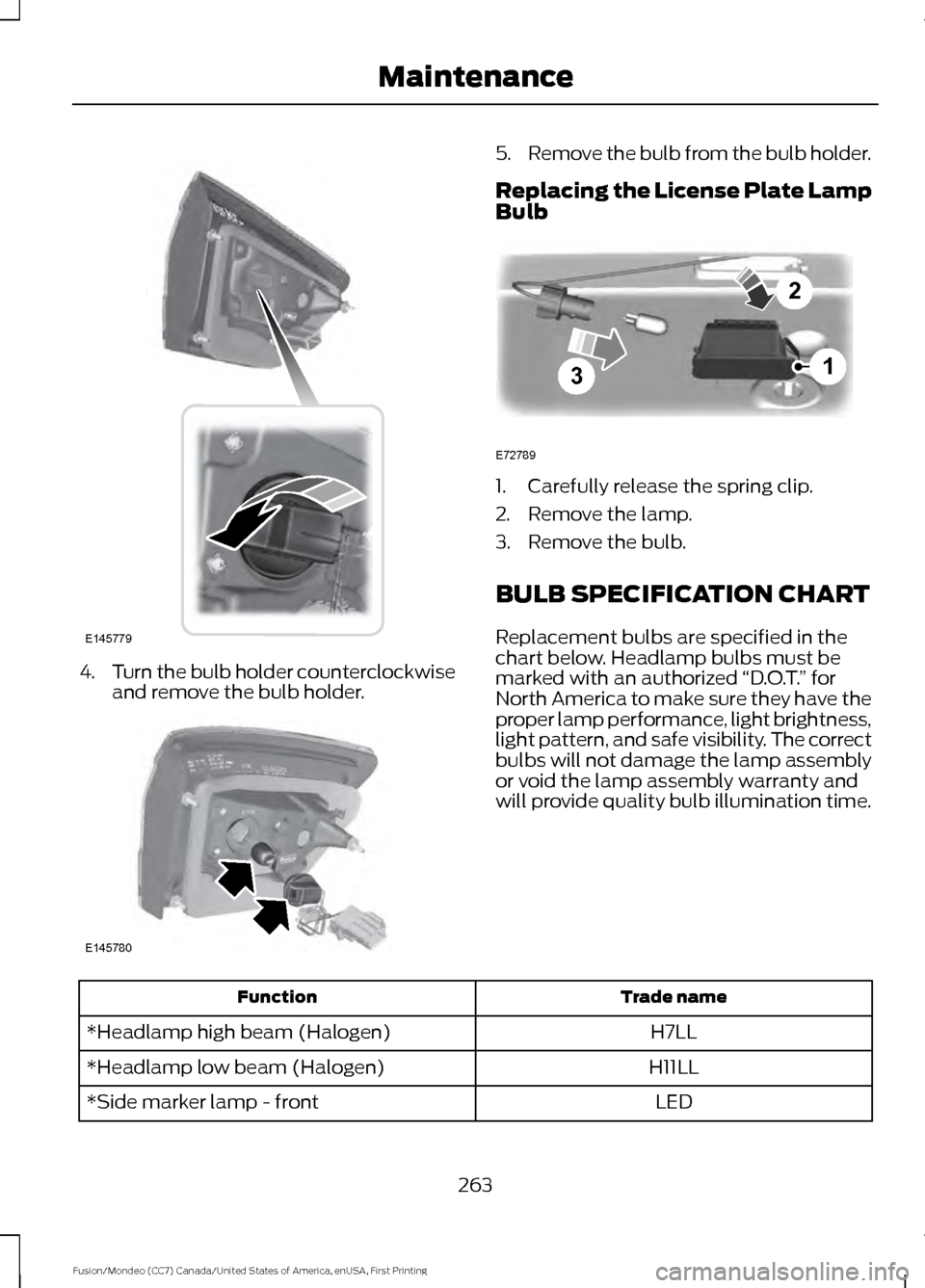
4.
Turn the bulb holder counterclockwise
and remove the bulb holder. 5.
Remove the bulb from the bulb holder.
Replacing the License Plate Lamp
Bulb 1. Carefully release the spring clip.
2. Remove the lamp.
3. Remove the bulb.
BULB SPECIFICATION CHART
Replacement bulbs are specified in the
chart below. Headlamp bulbs must be
marked with an authorized
“D.O.T.” for
North America to make sure they have the
proper lamp performance, light brightness,
light pattern, and safe visibility. The correct
bulbs will not damage the lamp assembly
or void the lamp assembly warranty and
will provide quality bulb illumination time. Trade name
Function
H7LL
*Headlamp high beam (Halogen)
H11LL
*Headlamp low beam (Halogen)
LED
*Side marker lamp - front
263
Fusion/Mondeo (CC7) Canada/United States of America, enUSA, First Printing MaintenanceE145779 E145780 3
2
1
E72789
Page 270 of 518

Note:
Never use abrasive materials, for
example steel wool or plastic pads as they
can scratch the chrome surface.
Note: Do not use chrome cleaner, metal
cleaner or polish on wheels or wheel covers.
Exterior Plastic Parts
For routine cleaning we recommend
Motorcraft Detail Wash. If tar or grease
spots are present, we recommend
Motorcraft Bug and Tar Remover.
Stripes or Graphics (If Equipped)
Do not use a commercial or high-pressure
sprayer on the surface or edge of stripes
and graphics. This can damage them and
cause the edges to peel away from the
vehicle surface.
Underbody
Flush the complete underside of your
vehicle frequently. Keep body and door
drain holes free of debris or foreign
material.
WAXING
Regular waxing is necessary to protect your
car's paint from the elements. We
recommend that you wash and wax the
painted surface once or twice a year.
When washing and waxing, park your
vehicle in a shaded area out of direct
sunlight. Always wash your vehicle before
applying wax.
• Use a quality wax that does not contain
abrasives.
• Follow the manufacturer ’s instructions
to apply and remove the wax.
• Apply a small amount of wax in a
back-and-forth motion, not in circles. •
Do not allow wax to come in contact
with any non-body (low-gloss black)
colored trim. The wax will discolor or
stain the parts over time.
•Roof racks.
• Bumpers.
• Grained door handles.
• Side moldings.
• Mirror housings.
• Windshield cowl area.
• Do not apply wax to glass areas.
• After waxing, your car's paint should
feel smooth, and be free of streaks and
smudges.
CLEANING THE ENGINE
Engines are more efficient when they are
clean because grease and dirt buildup keep
the engine warmer than normal.
When washing:
• Take care when using a power washer
to clean the engine. The high-pressure
fluid could penetrate the sealed parts
and cause damage.
• Do not spray a hot engine with cold
water to avoid cracking the engine
block or other engine components.
• Spray Motorcraft Engine Shampoo and
Degreaser on all parts that require
cleaning and pressure rinse clean. In
Canada, use Motorcraft Engine
Shampoo.
• Never wash or rinse the engine while it
is hot or running; water in the running
engine may cause internal damage.
267
Fusion/Mondeo (CC7) Canada/United States of America, enUSA, First Printing Vehicle Care
Page 278 of 518

What to do when a Tire Is
Punctured
A tire puncture within the tire tread area
can be repaired in two stages with the kit.
•
In the first stage, the tire will be
reinflated with a sealing compound
and air. After the tire has been
reinflated, you will need to drive the
vehicle a short distance 4 mi (6 km) to
distribute the sealant in the tire.
• In the second stage, you will need to
check the tire pressure and adjust, if
necessary, to the vehicle tire inflation
pressure.
First Stage: Reinflating the Tire
with Sealing Compound and Air WARNINGS
Do not stand directly over the kit
while inflating the tire. If you notice
any unusual bulges or deformations
in the tire sidewall during inflation, stop
and call roadside assistance. If the tire does not inflate to the
recommended tire pressure within
15 minutes, stop and call roadside
assistance. Preparation: Park the vehicle in a safe, level
and secure area, away from moving traffic.
Turn the hazard lights on. Apply the parking
brake and turn the engine off. Inspect the
flat tire for visible damage.
Sealant compound contains latex. To
avoid any allergic reactions, use the
non-latex gloves located in the accessory
box on the underside of the kit housing.
Do not remove any foreign object that has
pierced the tire. If a puncture is located in
the tire sidewall, stop and call roadside
assistance.
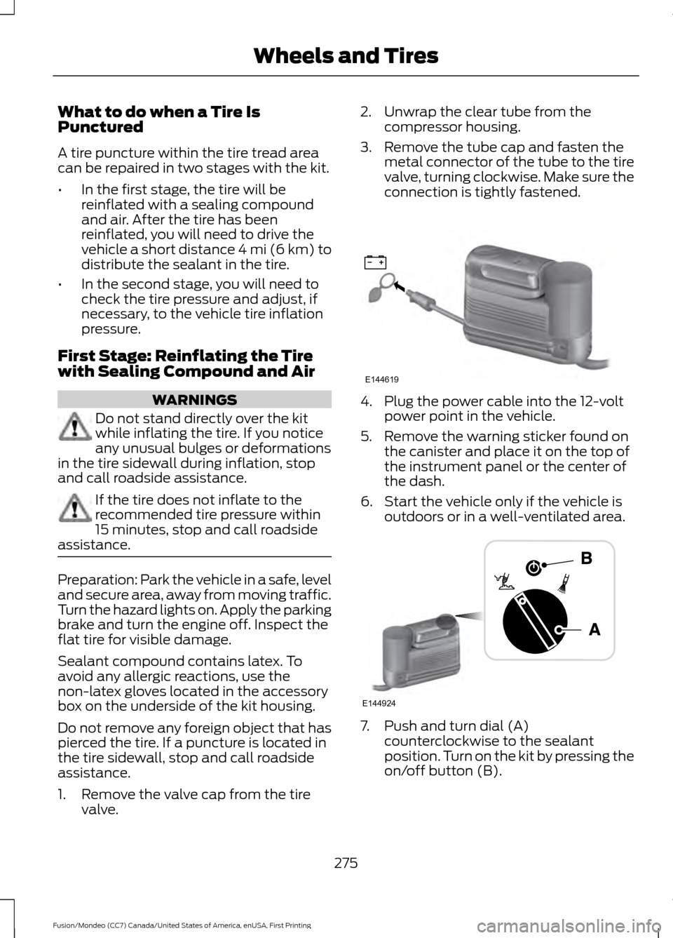
1. Remove the valve cap from the tire
valve. 2. Unwrap the clear tube from the
compressor housing.
3. Remove the tube cap and fasten the metal connector of the tube to the tire
valve, turning clockwise. Make sure the
connection is tightly fastened. 4. Plug the power cable into the 12-volt
power point in the vehicle.
5. Remove the warning sticker found on the canister and place it on the top of
the instrument panel or the center of
the dash.
6. Start the vehicle only if the vehicle is outdoors or in a well-ventilated area. 7. Push and turn dial (A)
counterclockwise to the sealant
position. Turn on the kit by pressing the
on/off button (B).
275
Fusion/Mondeo (CC7) Canada/United States of America, enUSA, First Printing Wheels and TiresE144619 E144924
Page 279 of 518

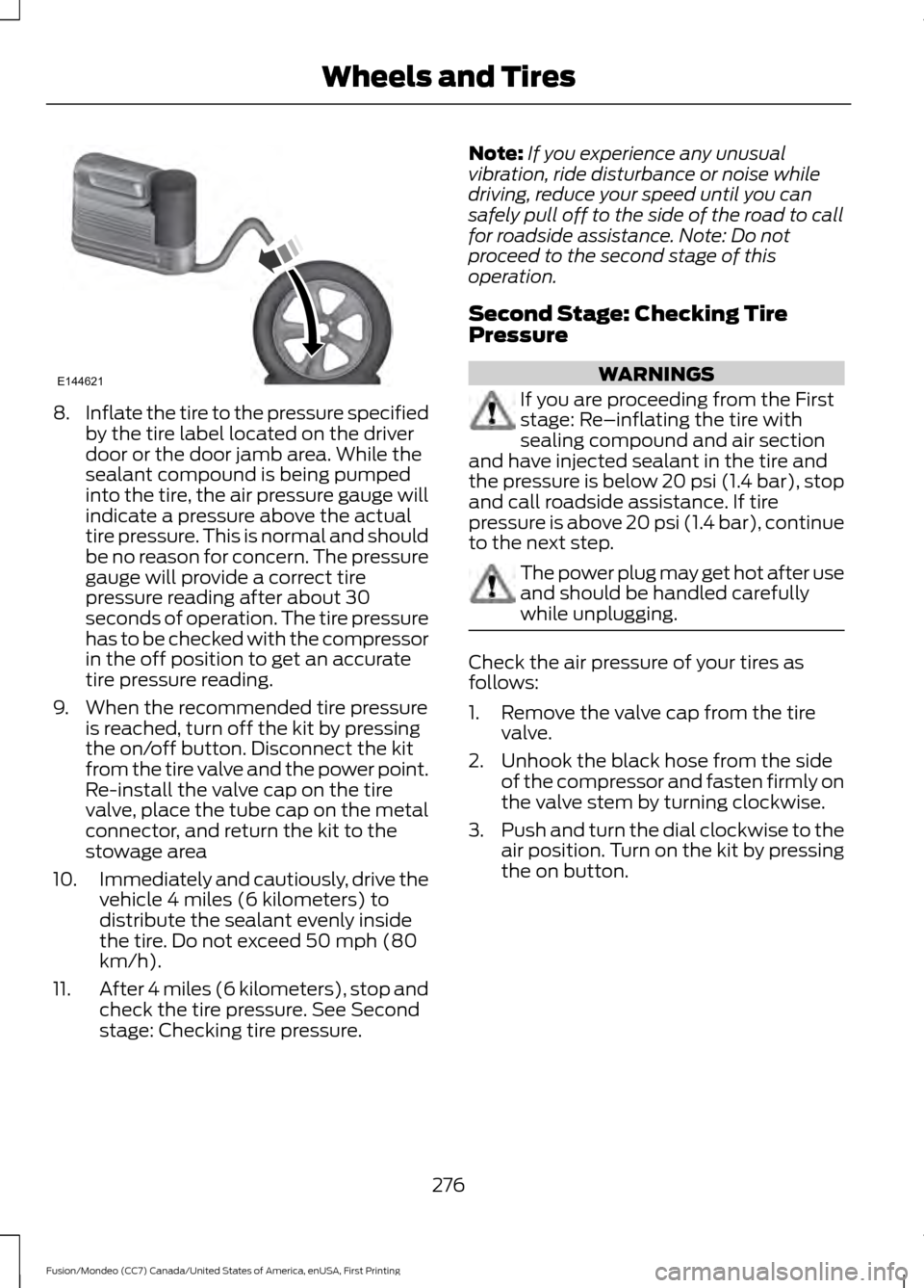
8.
Inflate the tire to the pressure specified
by the tire label located on the driver
door or the door jamb area. While the
sealant compound is being pumped
into the tire, the air pressure gauge will
indicate a pressure above the actual
tire pressure. This is normal and should
be no reason for concern. The pressure
gauge will provide a correct tire
pressure reading after about 30
seconds of operation. The tire pressure
has to be checked with the compressor
in the off position to get an accurate
tire pressure reading.
9. When the recommended tire pressure is reached, turn off the kit by pressing
the on/off button. Disconnect the kit
from the tire valve and the power point.
Re-install the valve cap on the tire
valve, place the tube cap on the metal
connector, and return the kit to the
stowage area
10. Immediately and cautiously, drive the
vehicle 4 miles (6 kilometers) to
distribute the sealant evenly inside
the tire. Do not exceed 50 mph (80
km/h).
11. After 4 miles (6 kilometers), stop and
check the tire pressure. See Second
stage: Checking tire pressure. Note:
If you experience any unusual
vibration, ride disturbance or noise while
driving, reduce your speed until you can
safely pull off to the side of the road to call
for roadside assistance. Note: Do not
proceed to the second stage of this
operation.
Second Stage: Checking Tire
Pressure WARNINGS
If you are proceeding from the First
stage: Re–inflating the tire with
sealing compound and air section
and have injected sealant in the tire and
the pressure is below 20 psi (1.4 bar), stop
and call roadside assistance. If tire
pressure is above 20 psi (1.4 bar), continue
to the next step. The power plug may get hot after use
and should be handled carefully
while unplugging.
Check the air pressure of your tires as
follows:
1. Remove the valve cap from the tire
valve.
2. Unhook the black hose from the side of the compressor and fasten firmly on
the valve stem by turning clockwise.
3. Push and turn the dial clockwise to the
air position. Turn on the kit by pressing
the on button.
276
Fusion/Mondeo (CC7) Canada/United States of America, enUSA, First Printing Wheels and TiresE144621