2016 FORD F450 SUPER DUTY lights
[x] Cancel search: lightsPage 137 of 507
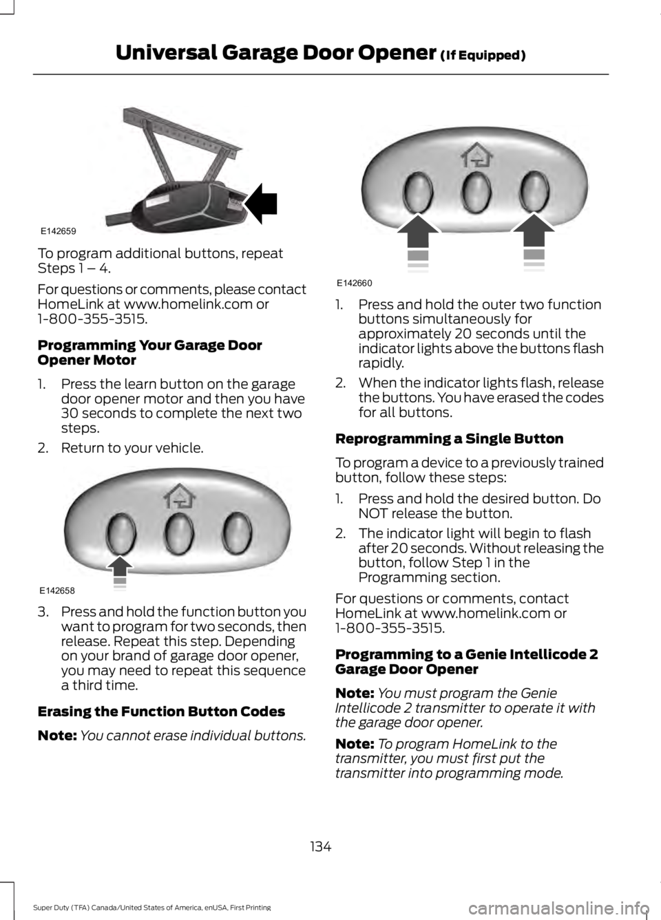
To program additional buttons, repeatSteps 1 – 4.
For questions or comments, please contactHomeLink at www.homelink.com or1-800-355-3515.
Programming Your Garage DoorOpener Motor
1. Press the learn button on the garagedoor opener motor and then you have30 seconds to complete the next twosteps.
2. Return to your vehicle.
3.Press and hold the function button youwant to program for two seconds, thenrelease. Repeat this step. Dependingon your brand of garage door opener,you may need to repeat this sequencea third time.
Erasing the Function Button Codes
Note:You cannot erase individual buttons.
1. Press and hold the outer two functionbuttons simultaneously forapproximately 20 seconds until theindicator lights above the buttons flashrapidly.
2.When the indicator lights flash, releasethe buttons. You have erased the codesfor all buttons.
Reprogramming a Single Button
To program a device to a previously trainedbutton, follow these steps:
1. Press and hold the desired button. DoNOT release the button.
2. The indicator light will begin to flashafter 20 seconds. Without releasing thebutton, follow Step 1 in theProgramming section.
For questions or comments, contactHomeLink at www.homelink.com or1-800-355-3515.
Programming to a Genie Intellicode 2Garage Door Opener
Note:You must program the GenieIntellicode 2 transmitter to operate it withthe garage door opener.
Note:To program HomeLink to thetransmitter, you must first put thetransmitter into programming mode.
134
Super Duty (TFA) Canada/United States of America, enUSA, First Printing
Universal Garage Door Opener (If Equipped)E142659 E142658 E142660
Page 138 of 507
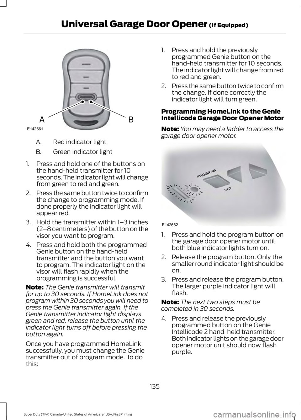
Red indicator lightA.
Green indicator lightB.
1. Press and hold one of the buttons onthe hand-held transmitter for 10seconds. The indicator light will changefrom green to red and green.
2.Press the same button twice to confirmthe change to programming mode. Ifdone properly the indicator light willappear red.
3. Hold the transmitter within 1–3 inches(2–8 centimeters) of the button on thevisor you want to program.
4. Press and hold both the programmedGenie button on the hand-heldtransmitter and the button you wantto program. The indicator light on thevisor will flash rapidly when theprogramming is successful.
Note:The Genie transmitter will transmitfor up to 30 seconds. If HomeLink does notprogram within 30 seconds you will need topress the Genie transmitter again. If theGenie transmitter indicator light displaysgreen and red, release the button until theindicator light turns off before pressing thebutton again.
Once you have programmed HomeLinksuccessfully, you must change the Genietransmitter out of program mode. To dothis:
1. Press and hold the previouslyprogrammed Genie button on thehand-held transmitter for 10 seconds.The indicator light will change from redto red and green.
2.Press the same button twice to confirmthe change. If done correctly theindicator light will turn green.
Programming HomeLink to the GenieIntellicode Garage Door Opener Motor
Note:You may need a ladder to access thegarage door opener motor.
1. Press and hold the program button onthe garage door opener motor untilboth blue indicator lights turn on.
2. Release the program button. Only thesmaller round indicator light should beon.
3.Press and release the program button.The larger purple indicator light willflash.
Note:The next two steps must becompleted in 30 seconds.
4. Press and release the previouslyprogrammed button on the GenieIntellicode 2 hand-held transmitter.Both indicator lights on the garage dooropener motor unit should now flashpurple.
135
Super Duty (TFA) Canada/United States of America, enUSA, First Printing
Universal Garage Door Opener (If Equipped)BAE142661 E142662
Page 162 of 507
•provides 4x4 High engagement anddisengagement while the vehicle ismoving.
•is operated by a rotary control locatedon the instrument panel that allowsyou select 4x2, 4x4 High or 4x4 Lowoperation.
•uses auto-manual hub locks that canbe engaged and disengagedautomatically based on the 4x4 modeselected.
•will increase fuel economy when usedin the recommended AUTO lock mode.
4WD Indicator Lights
Note:When a 4X4 system fault is present,the system will typically remain in whichever4X4 mode was selected prior to the faultcondition occurring. It will not default to 4X2in all circumstances. When this warning isdisplayed, have your vehicle serviced by anauthorized dealer.
4X2
Momentarily illuminates when2H is selected.
4X4 HIGH
Continuously illuminates when4H is selected.
4X4 LOW
Continuously illuminates when4L is selected.
CHECK 4X4
Displays when a 4X4 fault ispresent.
Using a Manual Shift On Stop(MSOS) 4WD system (If Equipped)
Note:High shift efforts may be encounteredwhen attempting to shift into and out of 4x4modes. It is recommended to allow thevehicle to roll at a speed below 3 mph(5 km/h) when shifting between modes.
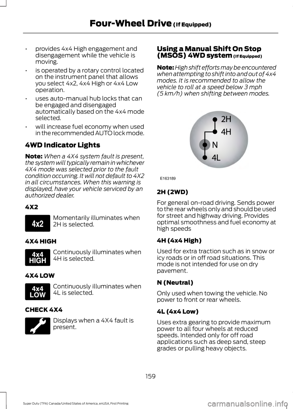
2H (2WD)
For general on-road driving. Sends powerto the rear wheels only and should be usedfor street and highway driving. Providesoptimal smoothness and fuel economy athigh speeds
4H (4x4 High)
Used for extra traction such as in snow oricy roads or in off road situations. Thismode is not intended for use on drypavement.
N (Neutral)
Only used when towing the vehicle. Nopower to front or rear wheels.
4L (4x4 Low)
Uses extra gearing to provide maximumpower to all four wheels at reducedspeeds. Intended only for off roadapplications such as deep sand, steepgrades or pulling heavy objects.
159
Super Duty (TFA) Canada/United States of America, enUSA, First Printing
Four-Wheel Drive (If Equipped)E163173 E163175 E163174 E163189
Page 173 of 507
PARKING BRAKE
WARNING
Always set the parking brake fullyand make sure the transmission isplaced in park (P). Failure to set theparking brake and engage park could resultin vehicle roll-away, property damage orbodily injury. Turn the ignition to the lockposition and remove the key whenever youleave your vehicle.
Apply the parking brake whenever yourvehicle is parked. Press the pedaldownward to set the parking brake. Thebrake warning lamp in the instrumentcluster will illuminate and remainsilluminated until the parking brake isreleased.
To release, pull the brake release leverlocated at the lower left side of theinstrument panel.
If you are parking your vehicle on a gradeor with a trailer, press and hold the brakepedal down, then set the parking brake.There may be a little vehicle movement asthe parking brake sets to hold the vehicle'sweight. This is normal and should be noreason for concern. If needed, press andhold the service brake pedal down, thentry reapplying the parking brake. Chock thewheels if required. If the parking brakecannot hold the weight of the vehicle, theparking brake may need to be serviced orthe vehicle may be overloaded.
HILL START ASSIST
WARNINGS
The system does not replace theparking brake. When you leave yourvehicle, always apply the parkingbrake. Failure to leave your vehicle securelyparked may lead to a crash or injury. SeeParking Brake (page 170).
WARNINGS
You must remain in your vehiclewhen the system turns on. At alltimes, you are responsible forcontrolling your vehicle, supervising thesystem and intervening, if required. Failureto take care may result in the loss ofcontrol of your vehicle, serious personalinjury or death.
The system will turn off if amalfunction is apparent or if you revthe engine excessively. Failure totake care may result in the loss of controlof your vehicle, serious personal injury ordeath.
The system makes it easier to pull awaywhen your vehicle is on a slope without theneed to use the parking brake.
When the system is active, your vehicleremains stationary on the slope for two tothree seconds after you release the brakepedal. This allows time to move your footfrom the brake to the accelerator pedal.The system releases the brakesautomatically once the engine hasdeveloped sufficient drive to prevent yourvehicle from rolling down the slope. Thisis an advantage when pulling away on aslope, for example from a car park ramp,traffic lights or when reversing uphill intoa parking space.
Note:The system only functions when youbring your vehicle to a complete standstillin an uphill gear (for example, drive whenfacing uphill or reverse when facingdownhill).
Note:There is no warning light to indicatethe system is either on or off.
Using Hill Start Assist
1. Press the brake pedal to bring yourvehicle to a complete standstill. Keepthe brake pedal pressed.
170
Super Duty (TFA) Canada/United States of America, enUSA, First Printing
Brakes
Page 176 of 507
System Indicator Lights andMessages
WARNING
If a failure has been detected withinthe AdvanceTrac system, thestability control light will illuminatesteadily. Verify that the traction controlsystem was not manually disabled usingthe stability control button. If the stabilitycontrol light still illuminates steadily, havethe system serviced by an authorizeddealer immediately. Operating your vehiclewith traction control disabled could leadto an increased risk of loss of vehiclecontrol, vehicle rollover, personal injury anddeath.
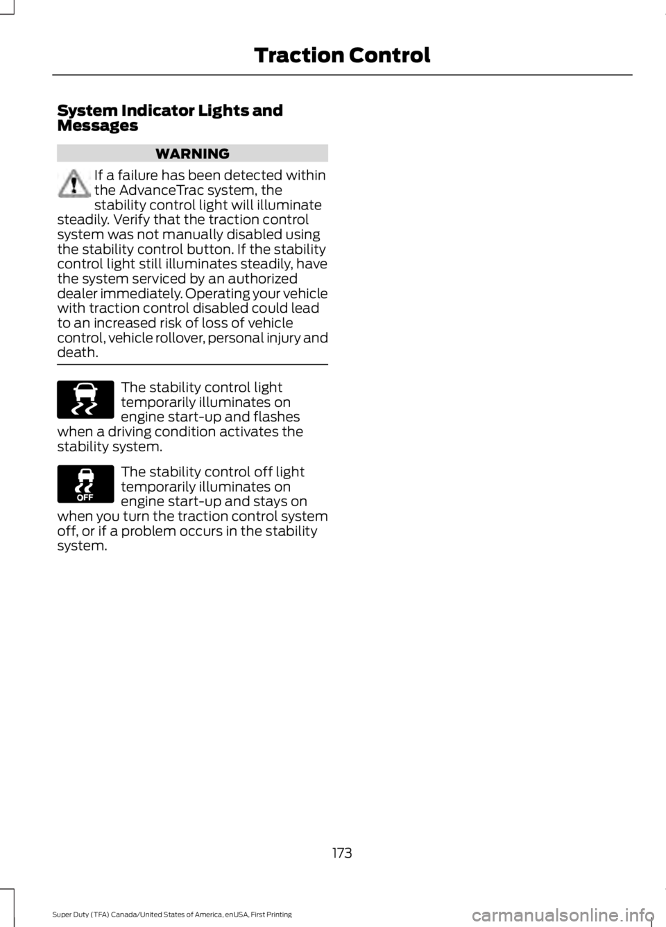
The stability control lighttemporarily illuminates onengine start-up and flasheswhen a driving condition activates thestability system.
The stability control off lighttemporarily illuminates onengine start-up and stays onwhen you turn the traction control systemoff, or if a problem occurs in the stabilitysystem.
173
Super Duty (TFA) Canada/United States of America, enUSA, First Printing
Traction ControlE138639
Page 185 of 507
Fixed guidelines are always shown in thedisplay, but the active guidelines onlydisplay when the steering wheel is turned.To use active guidelines, turn the steeringwheel to point the guidelines toward anintended path. If the steering wheelposition is changed while reversing, thevehicle might deviate from the originalintended path.
The active guidelines fade in and outdepending on the steering wheel position.The active guidelines are not shown whenthe steering wheel position is straight.
Always use caution while reversing.Objects in the red zone are closest to yourvehicle and objects in the green zone arefarther away. Objects are getting closer toyour vehicle as they move from the greenzone to the yellow or red zones. Use theside view mirrors and rear view mirror toget better coverage on both sides and rearof your vehicle.
Enhanced Park Aids
Note:Enhanced park aids is only availablewhen the transmission is in reverse (R).
Note:The reverse sensing system is noteffective at speeds above 3 mph (5 km/h)and may not detect certain angular ormoving objects.
The system uses red, yellow and greenhighlights which appear on top of the videoimage when an object is detected by thereverse sensing system. The alert highlightsthe closest object detected. The reversesensing alert can be disabled and if visualpark aid alert is enabled, highlighted areasare still displayed.
Selectable settings for this feature are ONand OFF.
Manual Zoom
WARNING
When manual zoom is on, the fullarea behind your vehicle is notshown. Be aware of yoursurroundings when using the manual zoomfeature.
Note:Manual zoom is only available whenthe transmission is in reverse (R).
Note:When manual zoom is enabled, onlythe centerline is shown.
This feature allows you to get a closer viewof an object behind your vehicle (forexample, a trailer). The zoomed imagekeeps the bumper in the image to providea reference. The zoom is only active whilethe transmission is in reverse (R). Whenthe transmission is shifted out of reverse(R), the feature automatically turns offand must be reset when it is used again.
Selectable settings for this feature is OFF,Level 1, Level 2 and Level 3. The selectedlevel will appear between the buttons (forexample, Level 1) The default setting forthe manual zoom is OFF.
Rear Camera Delay
When shifting the transmission out ofreverse (R) and into any gear other thanpark (P), the camera image remains in thedisplay until your vehicle speed reaches5 mph (8 km/h). This occurs when the rearcamera delay feature is on or until a radiobutton is selected.
Selectable settings for this feature are ONand OFF. The default setting for the rearcamera delay is ON.
182
Super Duty (TFA) Canada/United States of America, enUSA, First Printing
Parking Aids
Page 200 of 507
Remember to account for the trailertongue weight as part of your vehicle loadwhen calculating the total vehicle weight.
Trailer Towing Connector
When attaching the trailer wiring connectorto your vehicle, only use a proper fittingconnector that works with the vehicle andtrailer functions. Some seven-positionconnectors may have the SAE J2863 logo,which confirms that it is the proper wiringconnector and works correctly with yourvehicle.
FunctionColor
Left turn signal and stop lampYellow
Ground (-)White
Electric brakesBlue
Right turn signal and stoplampGreen
Battery (+)Orange
Running lightsBrown
Reverse lightsGrey
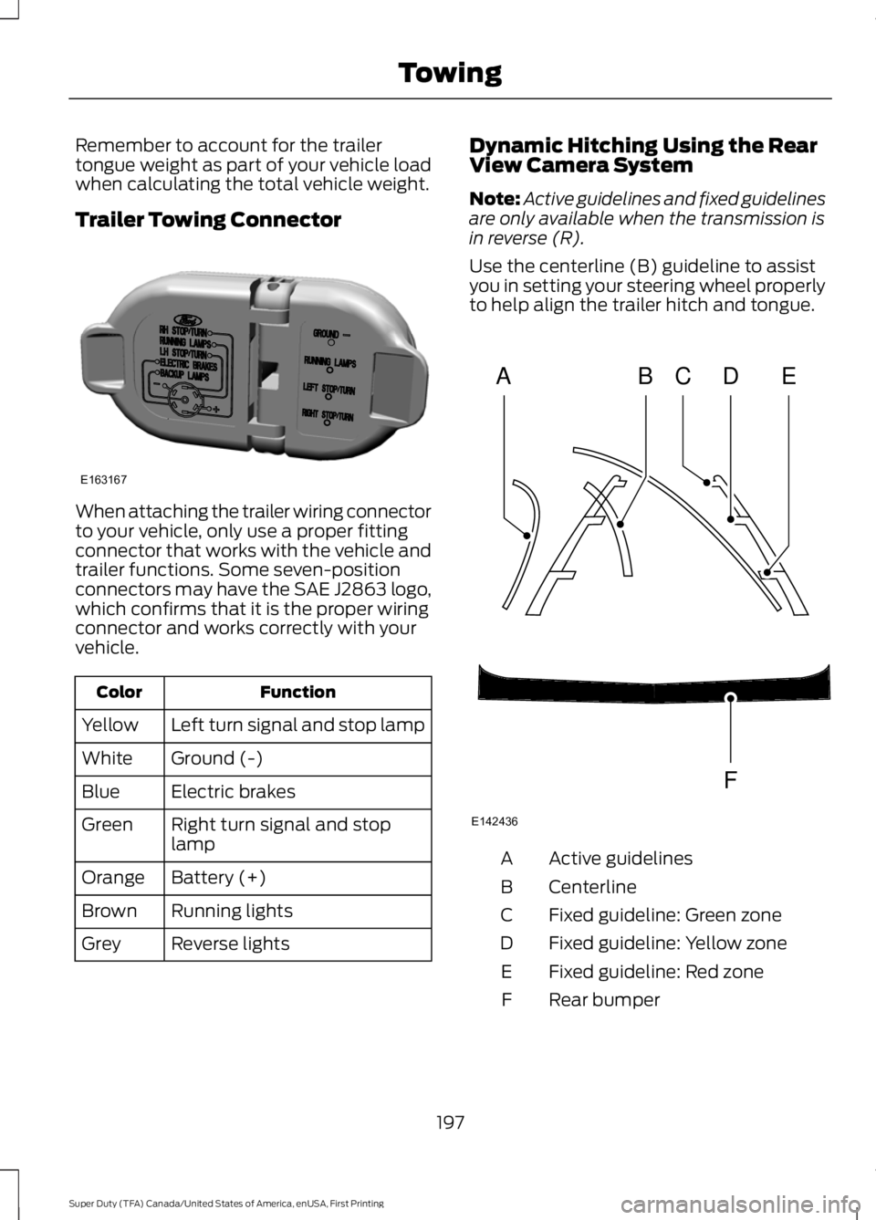
Dynamic Hitching Using the RearView Camera System
Note:Active guidelines and fixed guidelinesare only available when the transmission isin reverse (R).
Use the centerline (B) guideline to assistyou in setting your steering wheel properlyto help align the trailer hitch and tongue.
Active guidelinesA
CenterlineB
Fixed guideline: Green zoneC
Fixed guideline: Yellow zoneD
Fixed guideline: Red zoneE
Rear bumperF
197
Super Duty (TFA) Canada/United States of America, enUSA, First Printing
TowingE163167 ABCD
F
E
E142436
Page 203 of 507
Integrated Trailer Brake Controller
(If Equipped)
WARNING
The Ford trailer brake controller hasbeen verified to be compatible withtrailers having electric-actuateddrum brakes (one to four axles) and someelectric-over-hydraulic brakes. It will notactivate hydraulic surge-style trailerbrakes. It is the responsibility of thecustomer to ensure that the trailer brakesare adjusted appropriately, functioningnormally and all electric connections areproperly made. Failure to do so may resultin loss of vehicle control, crash or seriousinjury.
When used properly, the trailer brakecontroller assists in smooth and effectivetrailer braking by powering the trailer’selectric or electric-over-hydraulic brakeswith a proportional output based on thetowing vehicle’s brake pressure.
You can adjust the amount of initial trailerbrake output by selecting one of threesettings through the message center.
Ford has tested the trailer brake controllerto be compatible with several majorbrands of electric-over-hydraulic trailerbrakes. Contact an authorized dealer forinformation on which brands you can use.
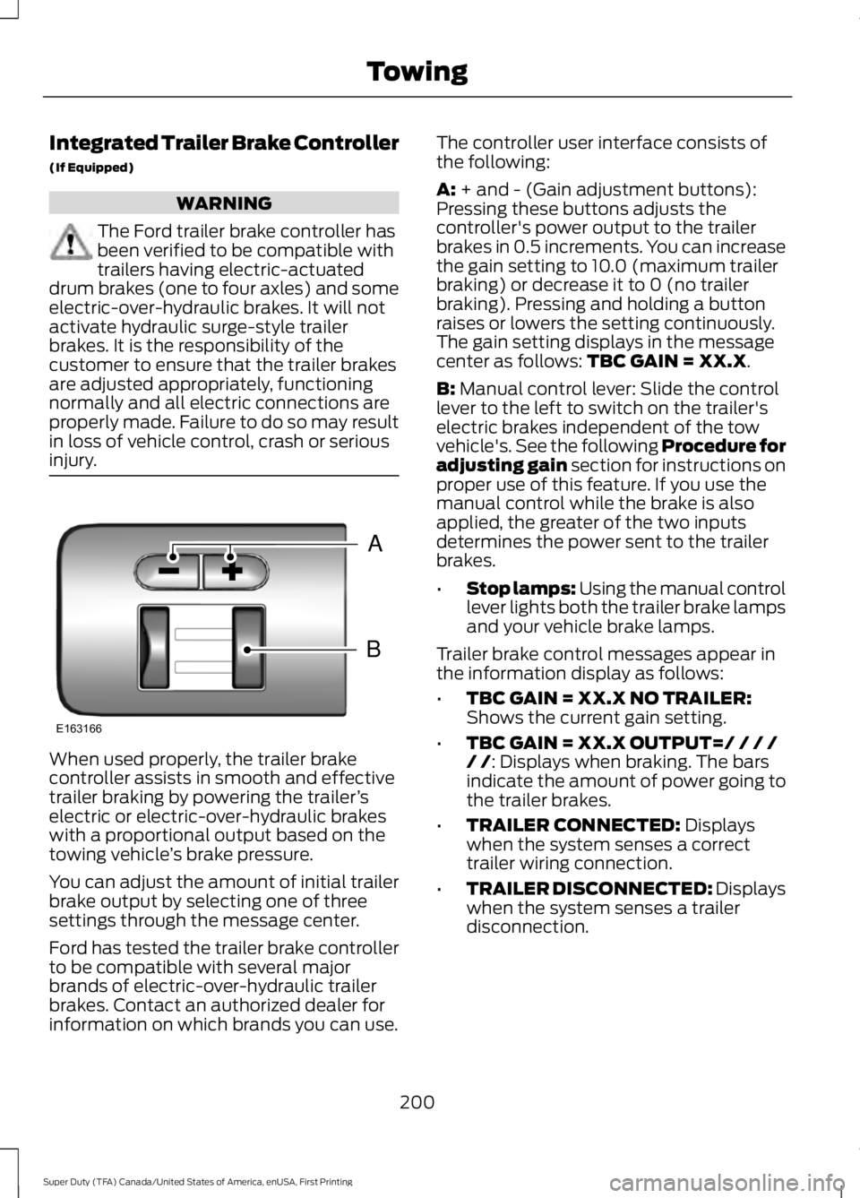
The controller user interface consists ofthe following:
A: + and - (Gain adjustment buttons):Pressing these buttons adjusts thecontroller's power output to the trailerbrakes in 0.5 increments. You can increasethe gain setting to 10.0 (maximum trailerbraking) or decrease it to 0 (no trailerbraking). Pressing and holding a buttonraises or lowers the setting continuously.The gain setting displays in the messagecenter as follows: TBC GAIN = XX.X.
B: Manual control lever: Slide the controllever to the left to switch on the trailer'selectric brakes independent of the towvehicle's. See the following Procedure foradjusting gain section for instructions onproper use of this feature. If you use themanual control while the brake is alsoapplied, the greater of the two inputsdetermines the power sent to the trailerbrakes.
•Stop lamps: Using the manual controllever lights both the trailer brake lampsand your vehicle brake lamps.
Trailer brake control messages appear inthe information display as follows:
•TBC GAIN = XX.X NO TRAILER:Shows the current gain setting.
•TBC GAIN = XX.X OUTPUT=/ / / // /: Displays when braking. The barsindicate the amount of power going tothe trailer brakes.
•TRAILER CONNECTED: Displayswhen the system senses a correcttrailer wiring connection.
•TRAILER DISCONNECTED: Displayswhen the system senses a trailerdisconnection.
200
Super Duty (TFA) Canada/United States of America, enUSA, First Printing
TowingB
A
E163166