2016 FORD EXPLORER instrument panel
[x] Cancel search: instrument panelPage 141 of 541
Fan speed control: Adjust the volume of air circulated in the vehicle.
A
Heated seats (if equipped):
Press the button to switch the heated seats on
and off. See Heated Seats (page 154).
B
Temperature control:
Control the temperature of the air circulated in your
vehicle.
C
Air distribution control:
Adjust the control to turn airflow from the instrument
panel or footwell vents on or off. You can distribute air through any combination
of these vents.
D
Fan speed control lock:
When illuminated, you can only operate the rear
passenger settings through the front controls.
E
HEATED WINDOWS AND
MIRRORS
(If Equipped)
Heated Rear Window
Note: Make sure the engine is running
before operating the heated windows. Press the button to clear the
heated rear window of thin ice
and fog. The heated rear window
will automatically turn off after a short
period of time. Start the engine before you
switch the heated rear window on.
Note: Do not use razor blades or other
sharp objects to clean or remove decals
from the inside of the heated rear window.
The vehicle warranty does not cover
damage caused to the heated rear window
grid lines.
Heated Exterior Mirror
When you switch the heated rear window
on, the heated exterior mirrors will
automatically turn on.
Note: Do not remove ice from the mirrors
with a scraper or adjust the mirror glass
when it is frozen in place.
Note: Do not clean the mirror housing or
glass with harsh abrasives, fuel or other
petroleum-based cleaning products. CABIN AIR FILTER
Your vehicle is equipped with a cabin air
filter, which gives you and your passengers
the following benefits:
•
It improves your driving comfort by
reducing particle concentration.
• It improves the interior compartment
cleanliness.
• It protects the climate control
components from particle deposits.
You can locate the cabin air filter behind
the glove box.
Note: Make sure you have a cabin air filter
installed at all times. This prevents foreign
objects from entering the system. Running
the system without a filter in place could
result in degradation or damage to the
system.
Replace the filter at regular intervals. See
Scheduled Maintenance
(page 486).
For additional cabin air filter information,
or to replace the filter, see an authorized
dealer.
138
Explorer (TUB), enUSA, First Printing Climate ControlE184884
Page 165 of 541
12 Volt DC Power Point
WARNINGS
Do not plug optional electrical
accessories into the cigar lighter
socket. Incorrect use of the cigar
lighter can cause damage not covered by
the vehicle warranty, and can result in fire
or serious injury. Do not use a power point for
operating a cigar lighter. Incorrect
use of the power points can cause
damage not covered by the vehicle
warranty, and can result in fire or serious
injury. Note:
When you switch the ignition on, you
can use the socket to power 12 volt
appliances with a maximum current rating
of 15 amps.
If the power supply does not work after you
switch the ignition off, switch the ignition
on.
Note: Do not hang any accessory from the
accessory plug.
Note: Do not use the power point over the
vehicle capacity of 12 volt DC 180 watts or
a fuse may blow.
Note: Always keep the power point caps
closed when not in use.
Do not insert objects other than an
accessory plug into the power point. This
will damage the power point and blow the
fuse.
Run the vehicle for full capacity use of the
power point.
To prevent the battery from running out of
charge:
• Do not use the power point longer than
necessary when the vehicle is not
running.
• Do not leave devices plugged in
overnight or when you park your vehicle
for extended periods. Locations
Power points may be in the following
locations:
•
On the lower instrument panel.
• Inside the center console.
• On the rear of the center console.
• In the rear cargo area.
110 Volt AC Power Point (If Equipped) WARNING
Do not keep electrical devices
plugged in the power point whenever
the device is not in use. Do not use
any extension cord with the 110 volt AC
power point, since it will defeat the safety
protection design. Doing so may cause the
power point to overload due to powering
multiple devices that can reach beyond
the 150 watt load limit and could result in
fire or serious injury. Note:
The power point will turn off when
the ignition is switched off or the battery
voltage drops below 11 volts.
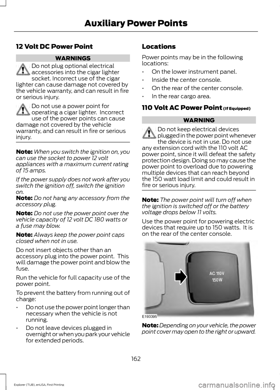
Use the power point for powering electric
devices that require up to 150 watts. It is
on the rear of the center console. Note:
Depending on your vehicle, the power
point cover may open to the right or upward.
162
Explorer (TUB), enUSA, First Printing Auxiliary Power PointsE193395
Page 185 of 541
Upshifts when accelerating (recom-
mended for best fuel economy)
Shift from:15 mph (24 km/h)
1 - 2
25 mph (40 km/h)
2 - 3
40 mph (64 km/h)
3 - 4
45 mph (72 km/h)
4 - 5
50 mph (80 km/h)
5 - 6
The instrument cluster will display the
selected gear that you are currently in and
a shift indicator arrow to assist in
optimizing shifting.
SelectShift will automatically make some
shifts for you in the event that your engine
speed is running at too high, or too low an
RPM.
Note: Engine damage may occur if
excessive engine revving is held without
shifting.
Brake-Shift Interlock WARNINGS
Do not drive your vehicle until you
verify that the brake lamps are
working.
When doing this procedure, you will
be taking the vehicle out of park
which means the vehicle can roll
freely. To avoid unwanted vehicle
movement, always fully set the parking
brake prior to doing this procedure. Use
wheel chocks if appropriate. If the parking brake is fully released,
but the brake warning lamp remains
illuminated, the brakes may not be
working properly. See your authorized
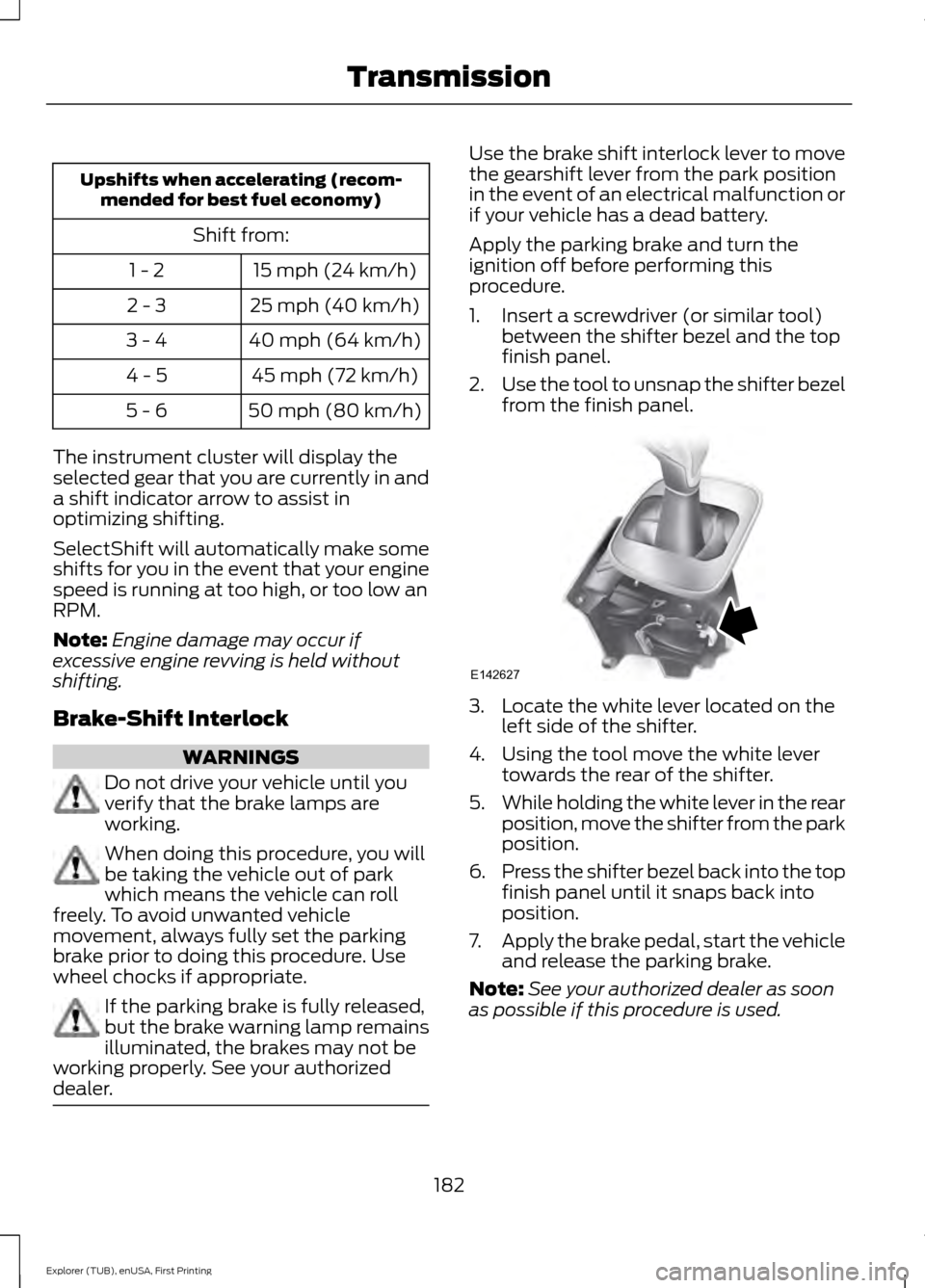
dealer. Use the brake shift interlock lever to move
the gearshift lever from the park position
in the event of an electrical malfunction or
if your vehicle has a dead battery.
Apply the parking brake and turn the
ignition off before performing this
procedure.
1. Insert a screwdriver (or similar tool)
between the shifter bezel and the top
finish panel.
2. Use the tool to unsnap the shifter bezel
from the finish panel. 3. Locate the white lever located on the
left side of the shifter.
4. Using the tool move the white lever towards the rear of the shifter.
5. While holding the white lever in the rear
position, move the shifter from the park
position.
6. Press the shifter bezel back into the top
finish panel until it snaps back into
position.
7. Apply the brake pedal, start the vehicle
and release the parking brake.
Note: See your authorized dealer as soon
as possible if this procedure is used.
182
Explorer (TUB), enUSA, First Printing TransmissionE142627
Page 195 of 541
PRINCIPLE OF OPERATION
The traction control system helps avoid
drive wheel spin and loss of traction.
If your vehicle begins to slide, the system
applies the brakes to individual wheels
and, when needed, reduces engine power
at the same time. If the wheels spin when
accelerating on slippery or loose surfaces,
the system reduces engine power in order
to increase traction.
USING TRACTION CONTROL
WARNING
The stability and traction control
light illuminates steadily if the
system detects a failure. Make sure
you did not manually disable the traction
control system using the information
display controls or the switch. If the
stability control and traction control light
is still illuminating steadily, have the
system serviced by an authorized dealer
immediately. Operating your vehicle with
the traction control disabled could lead to
an increased risk of loss of vehicle control,
vehicle rollover, personal injury and death. The system automatically turns on each
time you switch the ignition on.
If your vehicle is stuck in mud or snow,
switching traction control off may be
beneficial as this allows the wheels to spin.
Note:
When you switch traction control off,
stability control remains fully active.
Switching the System Off
When you switch the system off or on, a
message appears in the information
display showing system status.
You can switch the system off by either
using the information display controls or
the switch. Using the Information Display
Controls
You can switch this feature off or on in the
information display. See General
Information (page 101).
Using a Switch
(If Equipped)
The switch for the stability control system
and traction control system is on the
instrument panel.
Use the switch to turn the system off or
on.
System Indicator Lights and
Messages The stability and traction control
light temporarily illuminates on
engine start-up and flashes
when a driving condition activates either
of the systems. The stability and traction control
off light temporarily illuminates
on engine start-up and stays on:
• When you switch the traction control
system off.
• If a problem occurs in either of the
systems.
192
Explorer (TUB), enUSA, First Printing Traction ControlE138639
Page 259 of 541
Canadian roadside coverage and benefits
may differ from the U.S. coverage. If you
require more information, please refer to
the coverage section of your warranty
guide, call us in Canada at
1-800-665-2006, or visit our website at
www.ford.ca.
Sykes Assistance Services Corporation
administers the Roadside Assistance
program. You must receive covered
services in Canada or the continental
United States. Coverage extends to
vehicles that use public, non-seasonal,
annually traveled roadways. Roadside
Assistance coverage does not extend to
vehicles involved in cross-country driving,
logging, autocross and any other form of
off-road use. Well maintained roads and
surfaces help ensure safe travel for the
supplier, and allow their representatives
to perform service as per the standard
operating procedures.
In Remote Locations
If our supplier cannot take your vehicle by
road to the nearest authorized dealership,
transportation by rail or water may be
necessary. The program covers a tow to
the dock or rail terminal and also to the
dealership at the end of the trip.
For rail or water transportation, however,
contact your authorized dealer to confirm
if you are eligible for additional coverage
before you authorize or pay for the service.
Call Ford Roadside Assistance at
1-800-665-2006 for additional
information.
HAZARD WARNING FLASHERS
Note:
If used when the vehicle is not
running, the battery will lose charge. There
may be insufficient power to restart your
vehicle. The hazard warning button is
located on the instrument panel.
Use it when your vehicle is
creating a safety hazard for other
motorists.
• Press the button to turn on the hazard
warning function, and the front and
rear direction indicators will flash.
• Press the button again to turn them
off.
FUEL SHUTOFF WARNING
Failure to inspect and, if necessary,
repair fuel leaks after a collision may
increase the risk of fire and serious
injury. Ford Motor Company recommends
that the fuel system be inspected by an
authorized dealer after any collision. In the event of a moderate to severe
collision, this vehicle includes a fuel pump
shutoff feature that stops the flow of fuel
to the engine. Not every impact will cause
a shutoff.
Should your vehicle shut off after a
collision, you may restart your vehicle. For
vehicles equipped with a key system:
1. Switch off the ignition.
2. Switch on the ignition.
3. Repeat Steps 1 and 2 to re-enable the
fuel pump.
For vehicles equipped with a push button
start system:
1. Press the START/STOP button to
switch off the ignition.
2. Press the brake pedal and press the START/STOP
button to switch on the
ignition.
256
Explorer (TUB), enUSA, First Printing Roadside Emergencies
Page 272 of 541

Protected components
Fuse amp rating
Fuse or relay number
Trailer tow brake controller.
30A 3
46
Not used.
—
47
Body control module RP1 bus.
50A 3
48
Not used.
—
49
Body control module RP2 bus.
50A 3
50
Electronic fan relay 3.
50A 3
51
Anti-lock brake system pump.
60A 3
52
Not used.
—
53
Not used.
—
54
Not used.
—
55
Power inverter.
40A 2
56
Not used.
—
57
Not used.
—
58
Not used.
—
59
Power point (front console bin).
20A 2
60
Not used.
—
61
Power point (instrument panel).
20A 2
62
Fuel pump.
30A 2
63
Not used.
—
64
Power point (2nd row) (without USB
charger).
20A
2
65
Not used.
—
66
Power point (cargo area).
20A 2
67
Not used.
—
68
Power liftgate.
30A 2
69
269
Explorer (TUB), enUSA, First Printing Fuses
Page 274 of 541

Protected components
Fuse amp rating
Fuse or relay number
Alternator sense.
10A 1
93
Rear washer relay.
15A 1
94
Rear wiper relay.
15A 1
95
Powertrain control module relay coil
power.
10A
1
96
Rain sensor.
5A 1
97
2nd row seat motors.
20A 1
98
Trailer tow parking lamp relay.
20A 1
99
1 Micro fuse.
2 M-type fuse.
3 J-type fuse.
Passenger Compartment Fuse
Panel
The fuse panel is located under the
instrument panel to the left of the steering
column. Note:
It may be easier to access the fuse
panel if you remove the finish trim piece.
271
Explorer (TUB), enUSA, First Printing Fuses
Page 276 of 541

Protected components
Fuse amp rating
Fuse or relay number
Instrument cluster.
7.5A 2
13
Smart data link.
Steering column control module.
Not used.
—
14
Smart datalink connector power.
10A 2
15
Heads up display.
Not used.
—
16
Electronic finish panel.
5A 2
17
Push button start switch.
5A 2
18
Ignition switch.
Key inhibit.
Transmission control switch (tow haul).
7.5A 2
19
Not used.
—
20
Terrain management switch.
5A 2
21
Heads up display.
Humidity sensor.
Occupant classification sensor.
5A 2
22
Delayed accessory power.
10A 1
23
Power windows.
Moonroof.
Folding mirror relay.
DC inverter.
Window/moonroof switch illumination.
Central lock relay.
20A 1
24
Left-hand front smart window motor.
30A 1
25
Door zone module.
Right-hand front smart window motor.
30A 1
26
Door zone module.
Moonroof.
30A 1
27
Sony amplifier - 10 channel.
20A 1
28
Sony amplifier - 14 channel.
30A 1
29
273
Explorer (TUB), enUSA, First Printing Fuses