2016 FORD EXPEDITION height
[x] Cancel search: heightPage 37 of 421
Deactivating and Activating the
Belt-Minder Feature
WARNING
While the system allows you to
deactivate it, this system is designed
to improve your chances of being
safely belted and surviving an accident.
We recommend you leave the system
activated for yourself and others who may
use the vehicle. Read Steps 1 - 4 thoroughly before
proceeding with the programming
procedure.
Before following the procedure, make sure
that:
•
The parking brake is set.
• The transmission is in park (P).
• The ignition is off.
• All vehicle doors are closed.
• The driver safety belt is unbuckled.
1. Switch the ignition on. Do not start the
engine.
2. Wait until the safety belt warning light turns off (about one minute). After
Step 2, wait an additional 5 seconds
before proceeding with Step 3. Once
you start Step 3, you must complete
the procedure within 60 seconds.
3. Buckle then unbuckle the safety belt three times at a moderate speed,
ending in the unbuckled state. After
Step 3, the safety belt warning light
turns on.
4. While the safety belt warning light is on, buckle then unbuckle the safety
belt. After Step 4, the safety belt
warning light flashes for confirmation.
• This will switch the feature off if it is
currently on.
• This will switch the feature on if it is
currently off. CHILD RESTRAINT AND
SEATBELT MAINTENANCE
Inspect the vehicle safety belts and child
safety seat systems periodically to make
sure they work properly and are not
damaged. Inspect the vehicle and child
seat safety belts to make sure there are no
nicks, tears or cuts. Replace if necessary.
All vehicle safety belt assemblies, including
retractors, buckles, front safety belt buckle
assemblies, buckle support assemblies
(slide bar-if equipped), shoulder belt
height adjusters (if equipped), shoulder
belt guide on seat back (if equipped), child
safety seat LATCH and tether anchors, and
attaching hardware, should be inspected
after a crash. Read the child restraint
manufacturer's instructions for additional
inspection and maintenance information
specific to the child restraint.
Ford Motor Company recommends that
all safety belt assemblies in use in vehicles
involved in a crash be replaced. However,
if the crash was minor and an authorized
dealer finds that the belts do not show
damage and continue to operate properly,
they do not need to be replaced. Safety
belt assemblies not in use during a crash
should also be inspected and replaced if
either damage or improper operation is
noted.
Properly care for safety belts. See Vehicle
Care (page 264).
34
Expedition (TB7) Canada/United States of America, enUSA, First Printing Seatbelts
Page 198 of 421
Modes:
•
Comfort – Provides a more relaxed
driving experience, maximizing comfort.
Your steering effort decreases and the
suspension movement is more fluid.
Comfort mode is ideal when you desire
enhanced traveling comfort.
• Normal – Delivers a balanced
combination of comfortable, controlled
ride and confident handling. This mode
provides an engaging drive experience
and a direct connection to the road
without sacrificing any of the
composure demanded from your
vehicle.
• Sport – Provides a sportier driving
experience. The suspension stiffens,
with an emphasis on handling and
control. The engine responds more
directly to your inputs. Sport mode is
ideal for use during more spirited
driving.
Adaptive Steering
You can configure which of the modes are
active from the main menu on the
information display. See General
Information (page 92).
Modes:
• Normal – Default factory setting.
• Sport – Slightly higher effort required
for steering with more road force felt
through the steering wheel.
Note: The Drive Control has diagnostic
checks that continuously monitor the
system to ensure proper operation. Certain
types of system errors will gray out the
mode selections within the information
display, preventing you from changing states
when the gear position is changed. Other
types of errors will produce a temporary
message that states a malfunction. If either
condition persists for multiple key cycles,
have your vehicle checked by an authorized
dealer. SELF-LEVELING SUSPENSION
The self-leveling suspension system is
designed to improve ride, handling and
general vehicle performance during:
•
Certain road conditions
• Steering maneuvers
• Braking
• Acceleration
• Towing
This system keeps the rear of your vehicle
at a constant level through a hydraulic
pump inside each rear shock. Depending
on the payload or road surface conditions
it will take approximately 2 mi (3.2 km) for
the leveling to complete.
If the loaded vehicle is not moved for
approximately 12 hours, the leveling system
may bleed down to a lower height. This
can be especially apparent if a trailer is left
attached to the parked vehicle for long
periods of time. You must drive your vehicle
in order to re-level the suspension.
If a self-equalizing hitch is used, your
vehicle should be driven approximately
2 mi (3.2 km) with the trailer prior to
adjusting (leveling) the hitch.
195
Expedition (TB7) Canada/United States of America, enUSA, First Printing Driving Aids
Page 212 of 421
Integrated Hitch Rating
WARNING
Towing trailers beyond the maximum
tongue weight exceeds the limit of
the towing system and could result
in vehicle structural damage, loss of vehicle
control and personal injury. The standard integrated hitch has two
ratings depending on mode of operation:
•
Weight-carrying mode requires a draw
bar and hitch ball. The draw bar
supports all the vertical tongue load of
the trailer.
• Weight-distributing mode requires an
aftermarket weight-distributing
system, which includes draw bar, hitch
ball, spring bars and snap-up brackets.
This system distributes the vertical
tongue load of the trailer between the
truck and the trailer. Maximum Tongue Weight
Maximum Trailer Weight
Mode
600 lb (272 kg)
6000 lb (2721 kg)
Weight carrying
920 lb (417 kg)
9200 lb (4173 kg)
Weight distributing
Note: These are hitch ratings only. Actual
vehicle ratings are dependent on engine,
transmission and axle combinations.
Weight-distributing Hitch - Vehicles
without Automatic Leveling
Suspension WARNING
Do not adjust a weight-distributing
hitch to any position where the rear
bumper of the vehicle is higher than
it was before attaching the trailer. Doing
so will defeat the function of the
weight-distributing hitch, which may cause
unpredictable handling, and could result
in serious personal injury. When hooking-up a trailer using a
weight-distributing hitch, always use the
following procedure:
1. Park the loaded vehicle, without the
trailer, on a level surface.
2. Measure the height to the top of your vehicle's front wheel opening on the
fender. This is H1. 3.
Attach the loaded trailer to your vehicle
without the weight-distributing bars
connected.
4. Measure the height to the top of your vehicle's front wheel opening on the
fender a second time. This is H2.
5. Install and adjust the tension in the weight-distributing bars so that the
height of your vehicle's front wheel
opening on the fender is approximately
half the way down from H2, toward H1.
6. Check that the trailer is level or slightly
nose down toward your vehicle. If not,
adjust the ball height accordingly and
repeat Steps 2-6.
When the trailer is level or slightly nose
down toward the vehicle:
• Lock the bar tension adjuster in place.
• Check that the trailer tongue securely
attaches and locks onto the hitch.
• Install safety chains, lighting, and trailer
brake controls as required by law or the
trailer manufacturer.
209
Expedition (TB7) Canada/United States of America, enUSA, First Printing Towing
Page 213 of 421
Weight-distributing Hitch - Vehicles
with Automatic Leveling Suspension
WARNING
Do not adjust a weight-distributing
hitch to any position where the rear
bumper of the vehicle is higher than
it was before attaching the trailer. Doing
so will defeat the function of the
weight-distributing hitch, which may cause
unpredictable handling, and could result
in serious personal injury. Note:
If you do not move the loaded vehicle
for approximately 12 hours, the leveling
system may bleed down to a lower height.
This can be especially apparent if you leave
a trailer attached to the parked vehicle for
long periods. You must drive your vehicle in
order to re-level the suspension.
When hooking-up a trailer using a
weight-distributing hitch, always use the
following procedure:
1. Load the interior of the vehicle to a weight similar to that which you intend
to carry when towing. This includes
things such as passenger weight and
cargo.
2. Drive the vehicle for approximately 2 miles (3 kilometers) to re-level the
suspension.
3. Park the loaded vehicle, without the trailer, on a level surface.
4. Measure the height to the top of your vehicle's front wheel opening on the
fender. This is H1.
5. Attach the loaded trailer to your vehicle
without the weight-distributing bars
connected.
6. Make sure you securely attach and lock
the trailer tongue to the hitch.
7. Install safety chains, lighting, and trailer
brake controls as required by law or the
trailer manufacturer. 8. Drive the vehicle and trailer at 20–
25
mph (32 –40 km/h) for approximately
2 miles (3 kilometers) to re-level the
suspension.
9. Park your vehicle and trailer on a level surface.
10. Measure the height to the top of your
vehicle's front wheel opening on the
fender a second time. This is H2.
11. Install and adjust the tension in the weight-distributing bars so that the
height of your vehicle's front wheel
opening on the fender is
approximately half the way down
from H2, toward H1.
12. Check that the trailer is level or slightly nose down toward your
vehicle. If not, remove the trailer,
adjust the ball height accordingly and
repeat Steps 5-11.
When the trailer is level or slightly nose
down toward the vehicle:
• Lock the bar tension adjuster in place.
• Check that the trailer tongue securely
attaches and locks onto the hitch.
• Install safety chains, lighting, and trailer
brake controls as required by law or the
trailer manufacturer.
Safety Chains
Note: Do not attach safety chains to the
bumper.
Always connect the safety chains to the
frame or hook retainers of your vehicle
hitch.
To connect the safety chains, cross the
chains under the trailer tongue and allow
enough slack for turning tight corners. Do
not allow the chains to drag on the ground.
210
Expedition (TB7) Canada/United States of America, enUSA, First Printing Towing
Page 258 of 421
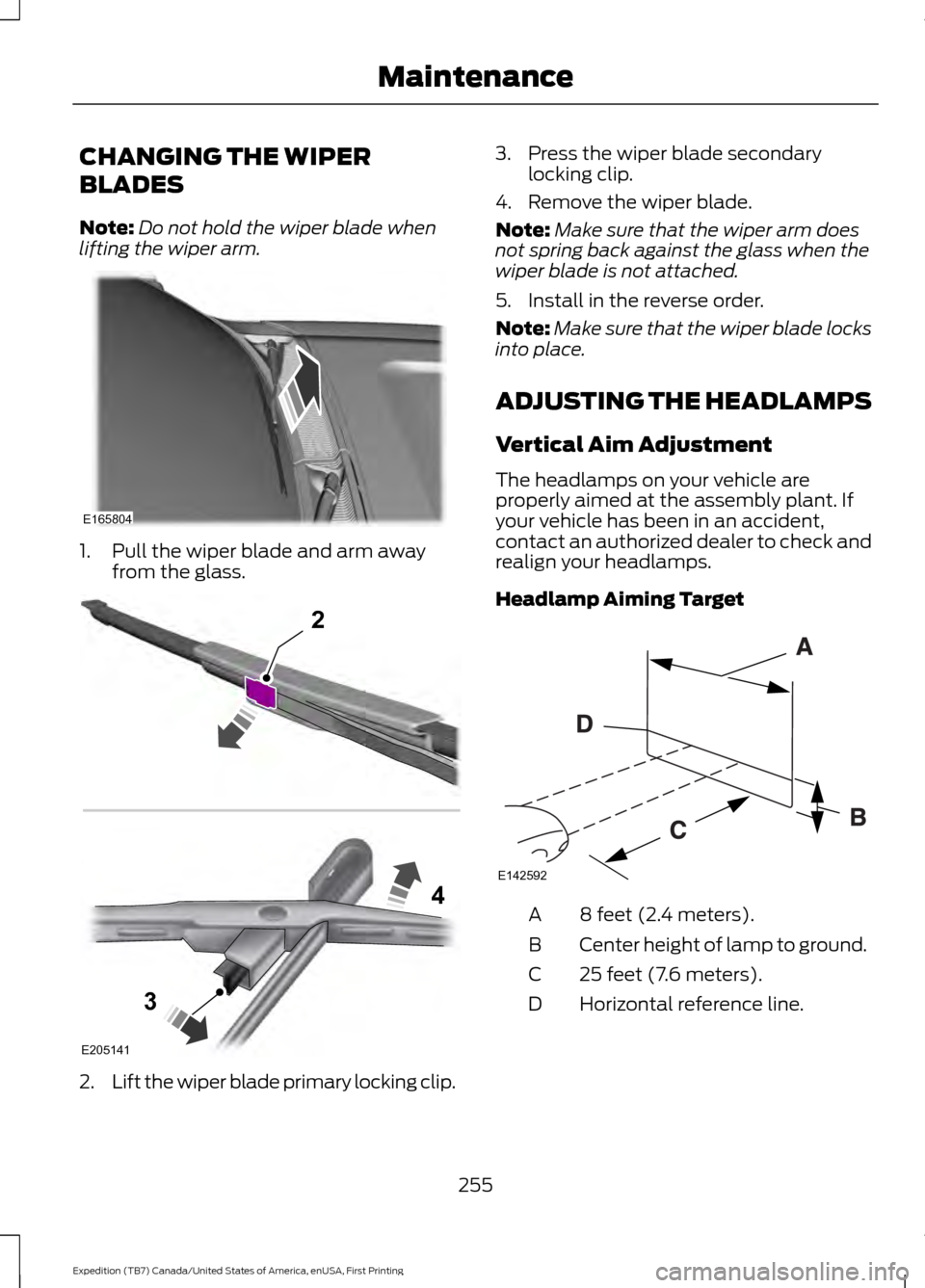
CHANGING THE WIPER
BLADES
Note:
Do not hold the wiper blade when
lifting the wiper arm. 1. Pull the wiper blade and arm away
from the glass. 2.
Lift the wiper blade primary locking clip. 3. Press the wiper blade secondary
locking clip.
4. Remove the wiper blade.
Note: Make sure that the wiper arm does
not spring back against the glass when the
wiper blade is not attached.
5. Install in the reverse order.
Note: Make sure that the wiper blade locks
into place.
ADJUSTING THE HEADLAMPS
Vertical Aim Adjustment
The headlamps on your vehicle are
properly aimed at the assembly plant. If
your vehicle has been in an accident,
contact an authorized dealer to check and
realign your headlamps.
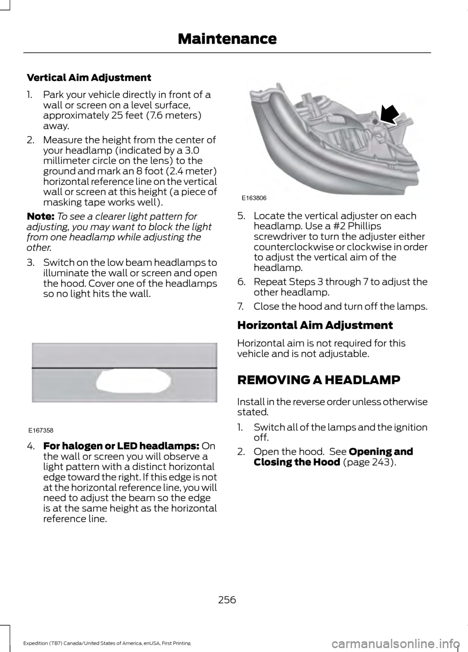
Headlamp Aiming Target 8 feet (2.4 meters).
A
Center height of lamp to ground.
B
25 feet (7.6 meters).
C
Horizontal reference line.
D
255
Expedition (TB7) Canada/United States of America, enUSA, First Printing MaintenanceE165804 E205141
2
3
4 E142592
Page 259 of 421
Vertical Aim Adjustment
1. Park your vehicle directly in front of a
wall or screen on a level surface,
approximately 25 feet (7.6 meters)
away.
2. Measure the height from the center of your headlamp (indicated by a 3.0
millimeter circle on the lens) to the
ground and mark an 8 foot (2.4 meter)
horizontal reference line on the vertical
wall or screen at this height (a piece of
masking tape works well).
Note: To see a clearer light pattern for
adjusting, you may want to block the light
from one headlamp while adjusting the
other.
3. Switch on the low beam headlamps to
illuminate the wall or screen and open
the hood. Cover one of the headlamps
so no light hits the wall. 4.
For halogen or LED headlamps: On
the wall or screen you will observe a
light pattern with a distinct horizontal
edge toward the right. If this edge is not
at the horizontal reference line, you will
need to adjust the beam so the edge
is at the same height as the horizontal
reference line. 5. Locate the vertical adjuster on each
headlamp. Use a #2 Phillips
screwdriver to turn the adjuster either
counterclockwise or clockwise in order
to adjust the vertical aim of the
headlamp.
6. Repeat Steps 3 through 7 to adjust the
other headlamp.
7. Close the hood and turn off the lamps.
Horizontal Aim Adjustment
Horizontal aim is not required for this
vehicle and is not adjustable.
REMOVING A HEADLAMP
Install in the reverse order unless otherwise
stated.
1. Switch all of the lamps and the ignition
off.
2. Open the hood. See Opening and
Closing the Hood (page 243).
256
Expedition (TB7) Canada/United States of America, enUSA, First Printing MaintenanceE167358 E163806
Page 281 of 421
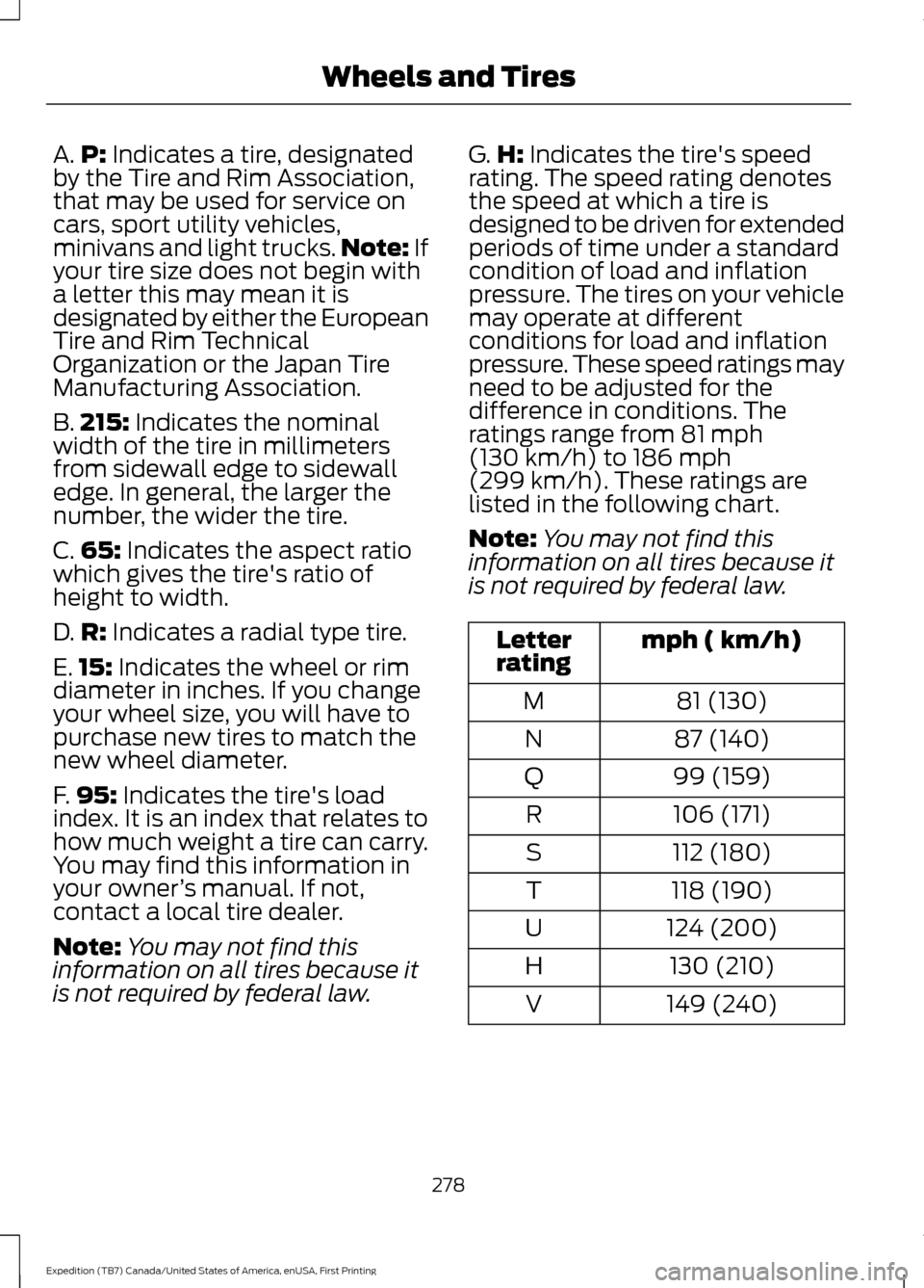
A.
P: Indicates a tire, designated
by the Tire and Rim Association,
that may be used for service on
cars, sport utility vehicles,
minivans and light trucks. Note:
If
your tire size does not begin with
a letter this may mean it is
designated by either the European
Tire and Rim Technical
Organization or the Japan Tire
Manufacturing Association.
B. 215:
Indicates the nominal
width of the tire in millimeters
from sidewall edge to sidewall
edge. In general, the larger the
number, the wider the tire.
C. 65:
Indicates the aspect ratio
which gives the tire's ratio of
height to width.
D. R:
Indicates a radial type tire.
E. 15:
Indicates the wheel or rim
diameter in inches. If you change
your wheel size, you will have to
purchase new tires to match the
new wheel diameter.
F. 95:
Indicates the tire's load
index. It is an index that relates to
how much weight a tire can carry.
You may find this information in
your owner ’s manual. If not,
contact a local tire dealer.
Note: You may not find this
information on all tires because it
is not required by federal law. G.
H:
Indicates the tire's speed
rating. The speed rating denotes
the speed at which a tire is
designed to be driven for extended
periods of time under a standard
condition of load and inflation
pressure. The tires on your vehicle
may operate at different
conditions for load and inflation
pressure. These speed ratings may
need to be adjusted for the
difference in conditions. The
ratings range from
81 mph
(130 km/h) to 186 mph
(299 km/h). These ratings are
listed in the following chart.
Note: You may not find this
information on all tires because it
is not required by federal law. mph ( km/h)
Letter
rating
81 (130)
M
87 (140)
N
99 (159)
Q
106 (171)
R
112 (180)
S
118 (190)
T
124 (200)
U
130 (210)
H
149 (240)
V
278
Expedition (TB7) Canada/United States of America, enUSA, First Printing Wheels and Tires
Page 285 of 421
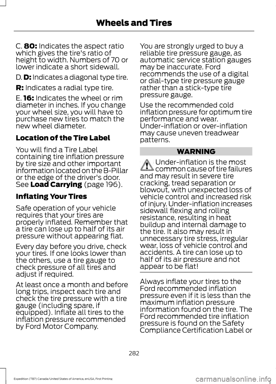
C.
80: Indicates the aspect ratio
which gives the tire's ratio of
height to width. Numbers of 70 or
lower indicate a short sidewall.
D. D:
Indicates a diagonal type tire.
R:
Indicates a radial type tire.
E. 16:
Indicates the wheel or rim
diameter in inches. If you change
your wheel size, you will have to
purchase new tires to match the
new wheel diameter.
Location of the Tire Label
You will find a Tire Label
containing tire inflation pressure
by tire size and other important
information located on the B-Pillar
or the edge of the driver's door.
See
Load Carrying (page 196).
Inflating Your Tires
Safe operation of your vehicle
requires that your tires are
properly inflated. Remember that
a tire can lose up to half of its air
pressure without appearing flat.
Every day before you drive, check
your tires. If one looks lower than
the others, use a tire gauge to
check pressure of all tires and
adjust if required.
At least once a month and before
long trips, inspect each tire and
check the tire pressure with a tire
gauge (including spare, if
equipped). Inflate all tires to the
inflation pressure recommended
by Ford Motor Company. You are strongly urged to buy a
reliable tire pressure gauge, as
automatic service station gauges
may be inaccurate. Ford
recommends the use of a digital
or dial-type tire pressure gauge
rather than a stick-type tire
pressure gauge.
Use the recommended cold
inflation pressure for optimum tire
performance and wear.
Under-inflation or over-inflation
may cause uneven treadwear
patterns.
WARNING
Under-inflation is the most
common cause of tire failures
and may result in severe tire
cracking, tread separation or
blowout, with unexpected loss of
vehicle control and increased risk
of injury. Under-inflation increases
sidewall flexing and rolling
resistance, resulting in heat
buildup and internal damage to
the tire. It also may result in
unnecessary tire stress, irregular
wear, loss of vehicle control and
accidents. A tire can lose up to
half of its air pressure and not
appear to be flat! Always inflate your tires to the
Ford recommended inflation
pressure even if it is less than the
maximum inflation pressure
information found on the tire. The
Ford recommended tire inflation
pressure is found on the Safety
Compliance Certification Label or
282
Expedition (TB7) Canada/United States of America, enUSA, First Printing Wheels and Tires