2016 FORD EXPEDITION EL brake light
[x] Cancel search: brake lightPage 176 of 421
PARKING BRAKE
WARNING
Always set the parking brake fullyand make sure the transmission isplaced in park (P). Failure to set theparking brake and engage park could resultin vehicle roll-away, property damage orbodily injury. Turn the ignition to the lockposition and remove the key whenever youleave your vehicle.
Apply the parking brake whenever yourvehicle is parked. Press the pedaldownward to set the parking brake. Thebrake warning lamp in the instrumentcluster will illuminate and remainsilluminated until the parking brake isreleased.
To release, pull the brake release leverlocated at the lower left side of theinstrument panel.
If you are parking your vehicle on a gradeor with a trailer, press and hold the brakepedal down, then set the parking brake.There may be a little vehicle movement asthe parking brake sets to hold the vehicle'sweight. This is normal and should be noreason for concern. If needed, press andhold the service brake pedal down, thentry reapplying the parking brake. Chock thewheels if required. If the parking brakecannot hold the weight of the vehicle, theparking brake may need to be serviced orthe vehicle may be overloaded.
HILL START ASSIST
WARNINGS
The system does not replace theparking brake. When you leave yourvehicle, always apply the parkingbrake and shift the transmission into park(P) (automatic transmission) or first gear(1) (manual transmission).
WARNINGS
You must remain in your vehicle onceyou have activated the system.
During all times, you are responsiblefor controlling your vehicle,supervising the system andintervening, if required.
If the engine is revved excessively, orif a malfunction is detected, thesystem will be deactivated.
The system makes it easier to pull awaywhen your vehicle is on a slope without theneed to use the parking brake.
When the system is active, your vehicle willremain stationary on the slope for two tothree seconds after you release the brakepedal. This allows you time to move yourfoot from the brake to the acceleratorpedal. The brakes release automaticallywhen the engine has sufficient torque toprevent your vehicle from rolling down thegrade. This is an advantage when pullingaway on a slope, for example from a carpark ramp, traffic lights or when reversinguphill into a parking space.
The system will activate automatically onany slope that will cause significant vehiclerollback. For vehicles with a manualtransmission, you can switch this featureoff using the information display. SeeInformation Displays (page 92). Thesystem will remain on or off depending onhow it was last set.
Note:There is no warning lamp to indicatethe system is either on or off.
Note:If your vehicle is equipped with AutoHold, Hill Start Assist will not be availablewhile Auto Hold is active.
173
Expedition (TB7) Canada/United States of America, enUSA, First Printing
Brakes
Page 178 of 421
PRINCIPLE OF OPERATION
The traction control system helps avoiddrive wheel spin and loss of traction.
If your vehicle begins to slide, the systemapplies the brakes to individual wheelsand, when needed, reduces engine powerat the same time. If the wheels spin whenaccelerating on slippery or loose surfaces,the system reduces engine power in orderto increase traction.
USING TRACTION CONTROL
WARNING
The stability and traction controllight illuminates steadily if thesystem detects a failure. Make sureyou did not manually disable the tractioncontrol system using the switch. If thestability control and traction control lightis still illuminating steadily, have thesystem serviced by an authorized dealerimmediately. Operating your vehicle withtraction control disabled could lead to anincreased risk of loss of vehicle control,vehicle rollover, personal injury and death.
The system automatically turns on eachtime you switch the ignition on.
If your vehicle is stuck in mud or snow,switching traction control off may bebeneficial as this allows the wheels to spin.
Note:When you switch traction control off,stability control remains fully active.
Switching the System Off
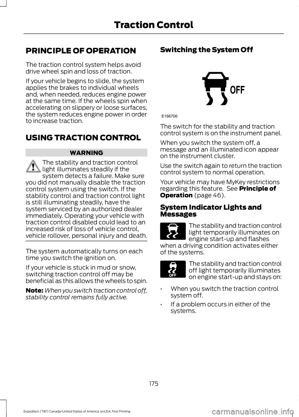
The switch for the stability and tractioncontrol system is on the instrument panel.
When you switch the system off, amessage and an illuminated icon appearon the instrument cluster.
Use the switch again to return the tractioncontrol system to normal operation.
Your vehicle may have MyKey restrictionsregarding this feature. See Principle ofOperation (page 46).
System Indicator Lights andMessages
The stability and traction controllight temporarily illuminates onengine start-up and flasheswhen a driving condition activates eitherof the systems.
The stability and traction controloff light temporarily illuminateson engine start-up and stays on:
•When you switch the traction controlsystem off.
•If a problem occurs in either of thesystems.
175
Expedition (TB7) Canada/United States of America, enUSA, First Printing
Traction ControlE166706 E138639
Page 179 of 421

PRINCIPLE OF OPERATION
WARNINGS
Vehicle modifications involvingbraking system, aftermarket roofracks, suspension, steering system,tire construction and wheel and tire sizemay change the handling characteristicsof your vehicle and may adversely affectthe performance of the electronic stabilitycontrol system. In addition, installing anystereo loudspeakers may interfere withand adversely affect the electronic stabilitycontrol system. Install any aftermarketstereo loudspeaker as far as possible fromthe front center console, the tunnel, andthe front seats in order to minimize the riskof interfering with the electronic stabilitycontrol sensors. Reducing theeffectiveness of the electronic stabilitycontrol system could lead to an increasedrisk of loss of vehicle control, vehiclerollover, personal injury and death.
Remember that even advancedtechnology cannot defy the laws ofphysics. It’s always possible to losecontrol of a vehicle due to inappropriatedriver input for the conditions. Aggressivedriving on any road condition can causeyou to lose control of your vehicleincreasing the risk of personal injury orproperty damage. Activation of theelectronic stability control system is anindication that at least some of the tireshave exceeded their ability to grip the road;this could reduce the operator’s ability tocontrol the vehicle potentially resulting ina loss of vehicle control, vehicle rollover,personal injury and death. If your electronicstability control system activates, SLOWDOWN.
The system automatically turns on eachtime you switch the ignition on.
If a driving condition activates either thestability control or the traction controlsystem you may experience the followingconditions:
•The stability and traction control lightflashes.
•Your vehicle slows down.
•Reduced engine power.
•A vibration in the brake pedal.
•The brake pedal is stiffer than usual.
•If the driving condition is severe andyour foot is not on the brake, the brakepedal may move as the systemsapplies higher brake forces.
The stability control system has severalfeatures built into it to help you maintaincontrol of your vehicle:
Electronic Stability Control
The system enhances your vehicle’s abilityto prevent skids or lateral slides byapplying brakes to one or more of thewheels individually and, if necessary,reducing engine power.
Roll Stability Control
The system enhances your vehicle’s abilityto prevent rollovers by detecting yourvehicle’s roll motion and the rate at whichit changes by applying the brakes to oneor more wheels individually.
Traction Control
The system enhances your vehicle’s abilityto maintain traction of the wheels bydetecting and controlling wheel spin. SeeUsing Traction Control (page 175).
176
Expedition (TB7) Canada/United States of America, enUSA, First Printing
Stability Control
Page 181 of 421
Stability Control and Traction Control with RSC Features
Disabled1Enabled1EnabledIlluminatedVehicle speedexceeds 35 mph(56 km/h) afterbutton ispressed andheld for morethan 5 seconds
EnabledEnabledEnabledNot illuminatedButton pressedagain afterdeactivation
Disabled 4DisabledDisabledIlluminatedButton notpressed and thetransfer case isswitched to
4WD Low3
1The traction control system may still be enabled but with higher entry thresholdscompared to the full system. The electronic stability control entry thresholds are highercompared to the full system.2When you press and hold the button for more than 5 seconds the indicator lamp blinksfor three seconds.3Your vehicle may or may not have this feature available. When you select 4WD low thestability control light illuminates and all stability control with RSC features are disabled.4Engine traction control and two-wheel spin brake traction control functions are disabled.Single wheel spin traction control is always enabled.
178
Expedition (TB7) Canada/United States of America, enUSA, First Printing
Stability Control
Page 208 of 421
TOWING A TRAILER
WARNINGS
Do not exceed the GVWR orthe GAWR specified on thecertification label.
Towing trailers beyond themaximum recommendedgross trailer weight exceeds thelimit of the vehicle and couldresult in engine damage,transmission damage, structuraldamage, loss of vehicle control,vehicle rollover and personalinjury.
Your vehicle may have electricalitems, such as fuses or relays,related to towing. See the Fuseschapter.
Your vehicle's load capacitydesignation is by weight, not byvolume, so you cannot necessarilyuse all available space whenloading a vehicle or trailer.
Towing a trailer places an extraload on your vehicle's engine,transmission, axle, brakes, tiresand suspension. Inspect thesecomponents periodically during,and after, any towing operation.
Load Placement
To help minimize how trailermovement affects your vehiclewhen driving:
•Load the heaviest items closestto the trailer floor.
•Load the heaviest itemscentered between the left andright side trailer tires.
•Load the heaviest items abovethe trailer axles or just slightlyforward toward the trailertongue. Do not allow the finaltrailer tongue weight to goabove or below 10-15% of theloaded trailer weight.
•Select a tow bar with thecorrect rise or drop. When boththe loaded vehicle and trailerare connected, the trailer frameshould be level, or slightlyangled down toward yourvehicle, when viewed from theside.
When driving with a trailer orpayload, a slight takeoff vibrationor shudder may be present due tothe increased payload weight.Additional information regardingproper trailer loading and settingyour vehicle up for towing islocated in another chapter of thismanual. See Load Limit (page198).
You can also find information inthe RV & Trailer Towing Guideavailable at your authorizeddealer, or online.
205
Expedition (TB7) Canada/United States of America, enUSA, First Printing
Towing
Page 209 of 421

RV & Trailer Towing Guide Online
http://www.fleet.ford.com/towing-guides/Website
TRAILER SWAY CONTROL
WARNING
Turning off trailer sway controlincreases the risk of loss of vehiclecontrol, serious injury or death. Forddoes not recommend disabling this featureexcept in situations where speed reductionmay be detrimental (such as hill climbing),the driver has significant trailer towingexperience, and can control trailer swayand maintain safe operation.
Note:This feature does not prevent trailersway, but reduces it once it begins.
Note:This feature cannot stop all trailersfrom swaying.
Note:In some cases, if vehicle speed is toohigh, the system may activate multipletimes, gradually reducing vehicle speed.
This feature applies your vehicle brakes atindividual wheels and, if necessary, reducesengine power. If the trailer begins to sway,the stability control light flashes and themessage TRAILER SWAY REDUCESPEED appears in the information display.The first thing to do is slow your vehicledown, then pull safely to the side of theroad and check for proper tongue load andtrailer load distribution. See LoadCarrying (page 196).
RECOMMENDED TOWING
WEIGHTS
Note:Do not exceed the trailer weight foryour vehicle configuration listed in the chartbelow.
Note:Make sure to take into considerationtrailer frontal area. Do not exceed 36.5 feet²(3.39 meters²) if your vehicle is equippedwith the standard towing package, or 60feet² (5.57 meters²) if your vehicle isequipped with the optional heavy dutypackage.
Note:Exceeding this limitation maysignificantly reduce the performance of yourtowing vehicle. Selecting a trailer with a lowaerodynamic drag and rounded front designhelps optimize performance and fueleconomy.
Note:For high altitude operation, reducethe gross combined weight by 2% per 1000feet (300 meters) starting at the 1000 foot(300 meter) elevation point.
Note:Certain states require electric trailerbrakes for trailers over a specified weight.Be sure to check state regulations for thisspecified weight. The maximum trailerweights listed may be limited to thisspecified weight, as the vehicle’s electricalsystem may not include the wiringconnector needed to activate electric trailerbrakes.
Your vehicle may tow a trailer provided themaximum trailer weight is less than orequal to the maximum trailer weight listedfor your vehicle configuration on thefollowing chart.
206
Expedition (TB7) Canada/United States of America, enUSA, First Printing
Towing
Page 211 of 421

ESSENTIAL TOWING CHECKS
Follow these guidelines for safe towing:
•Do not tow a trailer until you drive yourvehicle at least 1000 miles (1600kilometers).
•Consult your local motor vehicle lawsfor towing a trailer.
•See the instructions included withtowing accessories for the properinstallation and adjustmentspecifications.
•Service your vehicle more frequently ifyou tow a trailer. See your scheduledmaintenance information.
•If you use a rental trailer, follow theinstructions the rental agency givesyou.
See Load limits in the Load Carryingchapter for load specification terms foundon the tire label and Safety Compliancelabel and instructions on calculating yourvehicle's load.
Remember to account for the trailertongue weight as part of your vehicle loadwhen calculating the total vehicle weight.
Trailer Towing Connector(Vehicles with a Trailer TowingPackage and 7–Pin Connector)
When attaching the trailer wiring connectorto your vehicle, only use a proper fittingconnector that works with the vehicle andtrailer functions. Some seven-positionconnectors may have the SAE J2863 logo,which confirms that it is the proper wiringconnector and works correctly with yourvehicle.
FunctionColor
Left turn signal and stop lampYellow
Ground (-)White
Electric brakesBlue
Right turn signal and stoplampGreen
Battery (+)Orange
Running lightsBrown
Reverse lightsGrey
Hitches
WARNING
The trailer hitch on this vehicle is partof the vehicle rear crash safetystructure. Do not remove the trailerhitch. Failure to follow this warning couldcompromise vehicle crash structure andincrease the risk of injury in a rear endcrash.
Do not use a hitch that either clamps ontothe bumper or attaches to the axle.
Distribute the trailer load so 10-15% of thetotal trailer weight is on the tongue.
208
Expedition (TB7) Canada/United States of America, enUSA, First Printing
TowingE163167
Page 212 of 421
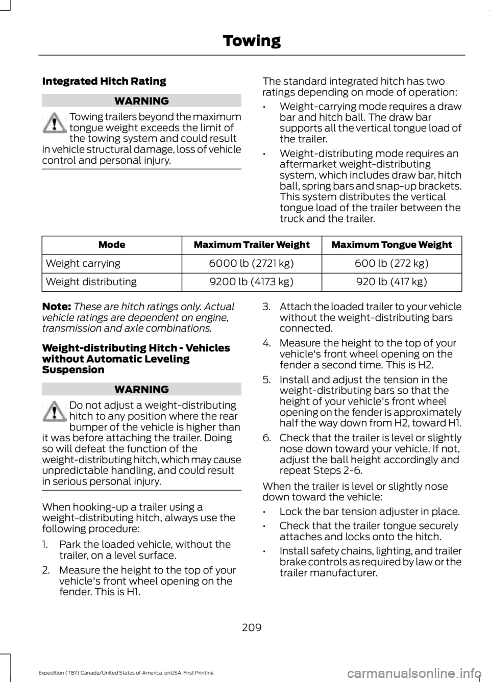
Integrated Hitch Rating
WARNING
Towing trailers beyond the maximumtongue weight exceeds the limit ofthe towing system and could resultin vehicle structural damage, loss of vehiclecontrol and personal injury.
The standard integrated hitch has tworatings depending on mode of operation:
•Weight-carrying mode requires a drawbar and hitch ball. The draw barsupports all the vertical tongue load ofthe trailer.
•Weight-distributing mode requires anaftermarket weight-distributingsystem, which includes draw bar, hitchball, spring bars and snap-up brackets.This system distributes the verticaltongue load of the trailer between thetruck and the trailer.
Maximum Tongue WeightMaximum Trailer WeightMode
600 lb (272 kg)6000 lb (2721 kg)Weight carrying
920 lb (417 kg)9200 lb (4173 kg)Weight distributing
Note:These are hitch ratings only. Actualvehicle ratings are dependent on engine,transmission and axle combinations.
Weight-distributing Hitch - Vehicleswithout Automatic LevelingSuspension
WARNING
Do not adjust a weight-distributinghitch to any position where the rearbumper of the vehicle is higher thanit was before attaching the trailer. Doingso will defeat the function of theweight-distributing hitch, which may causeunpredictable handling, and could resultin serious personal injury.
When hooking-up a trailer using aweight-distributing hitch, always use thefollowing procedure:
1. Park the loaded vehicle, without thetrailer, on a level surface.
2. Measure the height to the top of yourvehicle's front wheel opening on thefender. This is H1.
3.Attach the loaded trailer to your vehiclewithout the weight-distributing barsconnected.
4. Measure the height to the top of yourvehicle's front wheel opening on thefender a second time. This is H2.
5. Install and adjust the tension in theweight-distributing bars so that theheight of your vehicle's front wheelopening on the fender is approximatelyhalf the way down from H2, toward H1.
6.Check that the trailer is level or slightlynose down toward your vehicle. If not,adjust the ball height accordingly andrepeat Steps 2-6.
When the trailer is level or slightly nosedown toward the vehicle:
•Lock the bar tension adjuster in place.
•Check that the trailer tongue securelyattaches and locks onto the hitch.
•Install safety chains, lighting, and trailerbrake controls as required by law or thetrailer manufacturer.
209
Expedition (TB7) Canada/United States of America, enUSA, First Printing
Towing