2016 FIAT TIPO 5DOORS STATION WAGON lock
[x] Cancel search: lockPage 136 of 240
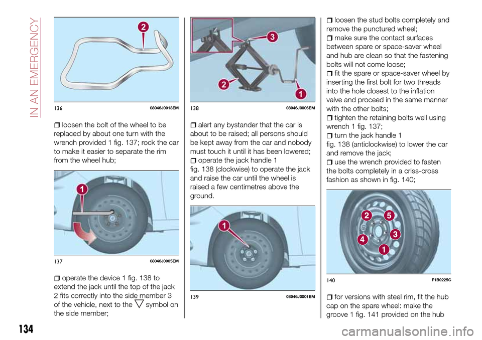
loosen the bolt of the wheel to be
replaced by about one turn with the
wrench provided 1 fig. 137; rock the car
to make it easier to separate the rim
from the wheel hub;
operate the device 1 fig. 138 to
extend the jack until the top of the jack
2 fits correctly into the side member 3
of the vehicle, next to the
symbol on
the side member;
alert any bystander that the car is
about to be raised; all persons should
be kept away from the car and nobody
must touch it until it has been lowered;
operate the jack handle 1
fig. 138 (clockwise) to operate the jack
and raise the car until the wheel is
raised a few centimetres above the
ground.
loosen the stud bolts completely and
remove the punctured wheel;
make sure the contact surfaces
between spare or space-saver wheel
and hub are clean so that the fastening
bolts will not come loose;
fit the spare or space-saver wheel by
inserting the first bolt for two threads
into the hole closest to the inflation
valve and proceed in the same manner
with the other bolts;
tighten the retaining bolts well using
wrench 1 fig. 137;
turn the jack handle 1
fig. 138 (anticlockwise) to lower the car
and remove the jack;
use the wrench provided to fasten
the bolts completely in a criss-cross
fashion as shown in fig. 140;
for versions with steel rim, fit the hub
cap on the spare wheel: make the
groove 1 fig. 141 provided on the hub
13608046J0013EM
13708046J0005EM
13808046J0006EM
13908046J0001EM
140F1B0225C
134
IN AN EMERGENCY
Page 139 of 240
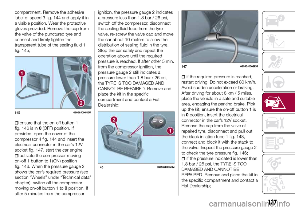
compartment. Remove the adhesive
label of speed 3 fig. 144 and apply it in
a visible position. Wear the protective
gloves provided. Remove the cap from
the valve of the punctured tyre and
connect and firmly tighten the
transparent tube of the sealing fluid 1
fig. 145;
ensure that the on-off button 1
fig. 146 is in0(OFF) position. If
provided, open the cover of the
compressor 4 fig. 144 and insert the
electrical connector in the car’s 12V
socket fig. 147, start the car engine;
activate the compressor moving
on-off 1 button toI(ON) position
fig. 146. When the pressure gauge 2
shows the car’s required pressure (see
section “Wheels” under “Technical data”
chapter), switch off the compressor
moving on-off button 1 to0position. If
after 5 minutes from the compressorignition, the pressure gauge 2 indicates
a pressure less than 1.8 bar / 26 psi,
switch off the compressor, disconnect
the sealing fluid tube from the tyre
valve, re-screw the valve cap and move
the car about 10 meters to allow the
distribution of sealing fluid in the tyre.
Stop the car safely and repeat the
operation above until the required
pressure is reached. If after other 5 min.
from the compressor ignition, the
pressure gauge 2 still indicates a
pressure lower than 1.8 bar / 26 psi,
the TYRE IS TOO DAMAGED AND
CANNOT BE REPAIRED. Remove and
place the kit in the specific
compartment and contact a Fiat
Dealership;
if the required pressure is reached,
restart driving. Do not exceed 80 km/h.
Avoid sudden acceleration or braking.
After driving for about 8 km / 5 miles,
place the vehicle in a safe and suitable
area, engaging the parking brake. Pick
up the kit, ensure the on-off button 1 is
in0position, insert the electrical
connector in the car’s 12V socket.
Remove the cap from the valve of
repaired tyre, disconnect and pull out
the black inflation tube 1 fig. 148,
connect and block it with the stack to
the valve. Inspect the pressure gauge 2
to check the tyre pressure fig. 146;
if the pressure indicated is lower than
1.8 bar / 26 psi, the TYRE IS TOO
DAMAGED AND CANNOT BE
REPAIRED. Remove and place the kit in
the specific compartment and contact a
Fiat Dealership;
14508056J0004EM
14608056J0005EM
14708056J0002EM
137
Page 140 of 240
if the pressure indicated is equal to or
higher than 1.8 bar / 26 psi, switch on
the compressor and reach the required
pressure. Disconnect and replace the
kit in the specific compartment.
Carefully drive and reach the Fiat
Dealership as soon as possible;
PRESSURE RESTORING
The compressor can also be used to
check and, if necessary, restore the tyre
pressure.
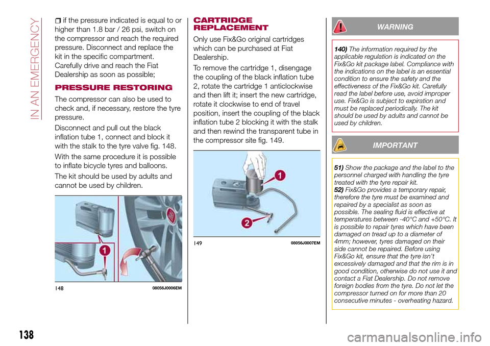
Disconnect and pull out the black
inflation tube 1, connect and block it
with the stalk to the tyre valve fig. 148.
With the same procedure it is possible
to inflate bicycle tyres and balloons.
The kit should be used by adults and
cannot be used by children.
CARTRIDGE
REPLACEMENT
Only use Fix&Go original cartridges
which can be purchased at Fiat
Dealership.
To remove the cartridge 1, disengage
the coupling of the black inflation tube
2, rotate the cartridge 1 anticlockwise
and then lift it; insert the new cartridge,
rotate it clockwise to end of travel
position, insert the coupling of the black
inflation tube 2 blocking it with the stalk
and then rewind the transparent tube in
the compressor site fig. 149.
WARNING
140)The information required by the
applicable regulation is indicated on the
Fix&Go kit package label. Compliance with
the indications on the label is an essential
condition to ensure the safety and the
effectiveness of the Fix&Go kit. Carefully
read the label before use, avoid improper
use. Fix&Go is subject to expiration and
must be replaced periodically. The kit
should be used by adults and cannot be
used by children.
IMPORTANT
51)Show the package and the label to the
personnel charged with handling the tyre
treated with the tyre repair kit.
52)Fix&Go provides a temporary repair,
therefore the tyre must be examined and
repaired by a specialist as soon as
possible. The sealing fluid is effective at
temperatures between -40°C and +50°C. It
is possible to repair tyres which have been
damaged on tread up to a diameter of
4mm; however, tyres damaged on their
side cannot be repaired. Before using
Fix&Go kit, ensure that the tyre isn't
excessively damaged and that the rim is in
good condition, otherwise do not use it and
contact a Fiat Dealership. Do not remove
foreign bodies from the tyre. Do not let the
compressor turned on for more than 20
consecutive minutes - overheating hazard.
14808056J0006EM
14908056J0007EM
138
IN AN EMERGENCY
Page 142 of 240
WARNING
141)Before opening the bonnet, make
sure that the engine is off and that the
ignition key is in the STOP position. Follow
the indications on the plate underneath the
bonnet. We recommend that you remove
the key from the ignition if other people
remain in the vehicle. The vehicle should
always be left after the key has been
removed or turned to the STOP position.
During refuelling, make sure that the engine
is off (and that the ignition key is in the
STOP position).
142)Do not get too close to the radiator
cooling fan: the electric fan may start;
danger of injury. Scarves, ties and other
loose clothing might be pulled by moving
parts.
143)Remove any metal objects (e.g. rings,
watches, bracelets), that might cause an
accidental electrical contact and cause
serious injury.
144)The batteries contain acid that can
burn skin or eyes. Batteries produce
hydrogen, which is easily flammable and
explosive. Therefore, keep away flames or
devices which may cause sparks.
IMPORTANT
53)Never use a fast battery-charger to
start the engine as this could damage the
electronic systems of your vehicle,
particularly the ignition and engine fuel
supply control units.54)Do not connect the cable to the
negative terminal (–) of the flat battery. The
following spark could lead to battery
explosion and cause serious harm. Only
use the specific earth point; do not use any
other exposed metallic part.
FUEL CUT-OFF
SYSTEM
DESCRIPTION
This intervenes in the case of an impact
causing:
the interruption of the fuel supply
with the engine consequently switching
off;
the automatic unlocking of the
doors;
turning on of the lights inside the
vehicle;
deactivation of climate control
system ventilation;
switching on of the hazard warning
lights (to deactivate the lights press the
button on the dashboard).
On some versions, the intervention of
the system is indicated by a message
shown on the display. In the same way,
a dedicated message on the display
warns the driver if system operation is
compromised.
IMPORTANT Carefully check the vehicle
for fuel leaks, for instance in the engine
compartment, under the vehicle or near
the tank area. After a collision, bring the
ignition device to STOP to prevent the
battery from running down.
140
IN AN EMERGENCY
Page 144 of 240
TOWING THE
VEHICLE
ATTACHING THE TOW
RING
146) 147) 148)
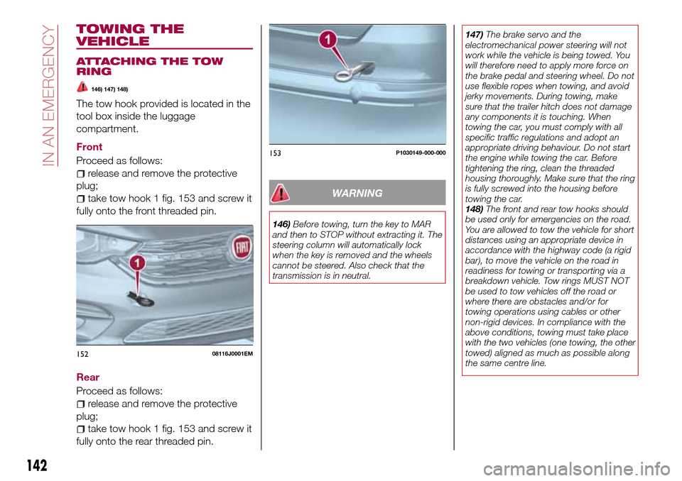
The tow hook provided is located in the
tool box inside the luggage
compartment.
Front
Proceed as follows:
release and remove the protective
plug;
take tow hook 1 fig. 153 and screw it
fully onto the front threaded pin.
Rear
Proceed as follows:
release and remove the protective
plug;
take tow hook 1 fig. 153 and screw it
fully onto the rear threaded pin.
WARNING
146)Before towing, turn the key to MAR
and then to STOP without extracting it. The
steering column will automatically lock
when the key is removed and the wheels
cannot be steered. Also check that the
transmission is in neutral.147)The brake servo and the
electromechanical power steering will not
work while the vehicle is being towed. You
will therefore need to apply more force on
the brake pedal and steering wheel. Do not
use flexible ropes when towing, and avoid
jerky movements. During towing, make
sure that the trailer hitch does not damage
any components it is touching. When
towing the car, you must comply with all
specific traffic regulations and adopt an
appropriate driving behaviour. Do not start
the engine while towing the car. Before
tightening the ring, clean the threaded
housing thoroughly. Make sure that the ring
is fully screwed into the housing before
towing the car.
148)The front and rear tow hooks should
be used only for emergencies on the road.
You are allowed to tow the vehicle for short
distances using an appropriate device in
accordance with the highway code (a rigid
bar), to move the vehicle on the road in
readiness for towing or transporting via a
breakdown vehicle. Tow rings MUST NOT
be used to tow vehicles off the road or
where there are obstacles and/or for
towing operations using cables or other
non-rigid devices. In compliance with the
above conditions, towing must take place
with the two vehicles (one towing, the other
towed) aligned as much as possible along
the same centre line.
15208116J0001EM
153P1030149-000-000
142
IN AN EMERGENCY
Page 148 of 240

Thousands of kilometres15 30 45 60 75 90 105 120 135 150
Years12345678910
Check cleanliness of bonnet and luggage compartment
locks, cleanliness and lubrication of linkage●●●●●
Check handbrake lever travel and adjust, if necessary●●●●●
Visually inspect conditions and wear of front and rear disc
brake pads and operation of pad wear indicator●●●●●●●●●●
Visually inspect conditions of toothed timing drive belt●●
Visually inspect condition of the accessory drive belt(s)●●
Check tension of accessory drive belt (for versions without
automatic tensioner)●●
Change engine oil and replace oil filter (2) (o) (●)o●o●o●o●o●
Replace spark plugs (1.4 16V 95 HP versions)●●
Replace spark plugs (1.4 T-jet 120 HP versions)(3)●●●●●
Replace the toothed timing drive belt(4)
(2) If the car's annual mileage is less than 10,000 km, the engine oil and filter must be replaced every year. (o) Recommended operations
(●) Mandatory operations
(3)For T-Jet versions, in order to guarantee correct operation and prevent serious damage to the engine, it is essential to observe the following:
only use spark plugs specifically certified for these engines; all spark plugs should be of the same type and brand (see the “Engine”
paragraph in the "Technical Specifications" section); strictly comply with the replacement intervals in the Scheduled Servicing Plan; you are
advised to contact a Dealership to have the plugs replaced.
(4) Areas that are not dusty: recommended maximum mileage 120,000 km. The belt must be replaced every 6 years, regardless of distance
travelled. Dusty areas and/or demanding use of the car (cold climates, town use, long periods of idling): advised maximum mileage
60,000 km. The belt must be replaced every 4 years, regardless of distance travelled.
146
SERVICING AND CARE
Page 151 of 240
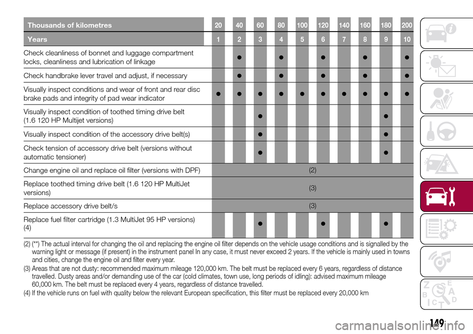
Thousands of kilometres20 40 60 80 100 120 140 160 180 200
Years12345678910
Check cleanliness of bonnet and luggage compartment
locks, cleanliness and lubrication of linkage●●●●●
Check handbrake lever travel and adjust, if necessary●●●●●
Visually inspect conditions and wear of front and rear disc
brake pads and integrity of pad wear indicator●●●●●●●●●●
Visually inspect condition of toothed timing drive belt
(1.6 120 HP Multijet versions)●●
Visually inspect condition of the accessory drive belt(s)●●
Check tension of accessory drive belt (versions without
automatic tensioner)●●
Change engine oil and replace oil filter (versions with DPF)(2)
Replace toothed timing drive belt (1.6 120 HP MultiJet
versions)(3)
Replace accessory drive belt/s(3)
Replace fuel filter cartridge (1.3 MultiJet 95 HP versions)
(4)
●●●
(2) (**) The actual interval for changing the oil and replacing the engine oil filter depends on the vehicle usage conditions and is signalled by the
warning light or message (if present) in the instrument panel In any case, it must never exceed 2 years. If the vehicle is mainly used in towns
and cities, change the engine oil and filter every year.
(3) Areas that are not dusty: recommended maximum mileage 120,000 km. The belt must be replaced every 6 years, regardless of distance
travelled. Dusty areas and/or demanding use of the car (cold climates, town use, long periods of idling): advised maximum mileage
60,000 km. The belt must be replaced every 4 years, regardless of distance travelled.
(4) If the vehicle runs on fuel with quality below the relevant European specification, this filter must be replaced every 20,000 km
149
Page 153 of 240
PERIODIC CHECKS
Every1,000km or before long trips
check and, if necessary, top up:
engine coolant level;
brake fluid level;
windscreen washer fluid level;
tyre inflation pressure and condition;
operation of lighting system
(headlights, direction indicators, hazard
warning lights, etc.);
operation of screen washer/wiper
system and positioning/wear of
windscreen/rear window wiper blades.
Every3,000km, check and top up if
required: engine oil level.
DEMANDING USE OF THE
CAR
If the vehicle is used mainly under one
of the following conditions:
dusty roads;
short, repeated journeys (less than
7-8 km) at sub-zero outside
temperatures;
engine often idling or driving long
distances at low speeds or long periods
of inactivity;
the following checks must be carried
out more often than indicated in the
Scheduled Servicing Plan:
check front disc brake pad condition
and wear;
check cleanliness of bonnet and
luggage compartment locks,cleanliness and lubrication of linkage;
visually inspect conditions of: engine,
gearbox, transmission, pipes and hoses
(exhaust/fuel system/brakes) and
rubber elements (gaiters/sleeves/
bushes, etc.);
check battery charge and battery
fluid level (electrolyte);
visually inspect conditions of the
accessory drive belts;
check and, if necessary, change
engine oil and replace oil filter;
check and, if necessary, replace
pollen filter;
check and, if necessary, replace air
cleaner.
151