Page 131 of 240
LUGGAGE
COMPARTMENT FUSE
BOX
Open the tailgate and then move the
section of the inner cover fig. 131 and
access the fuses in fuse box 2 fig. 132.
130P2000083-000-000
131P1030208-000-000
13208036J0011EM
129
UNDER DASHBOARD
CONTROL UNIT
The control unit fig. 130 is located to
the left side under the dashboard.
Page 133 of 240
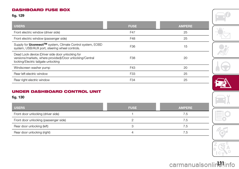
DASHBOARD FUSE BOX
fig. 129
USERSFUSE AMPERE
Front electric window (driver side) F47 25
Front electric window (passenger side) F48 25
Supply forUconnect
™system, Climate Control system, EOBD
system, USB/AUX port, steering wheel controls.F36 15
Dead Lock device (Driver side door unlocking for
versions/markets, where provided)/Door unlocking/Central
locking/Electric tailgate unlockingF38 20
Windscreen washer pump F43 20
Rear left electric window F33 25
Rear right electric window F34 25
UNDER DASHBOARD CONTROL UNIT
fig. 130
USERSFUSE AMPERE
Front door unlocking (driver side) 1 7.5
Front door unlocking (passenger side) 2 7.5
Rear door unlocking (left) 3 7.5
Rear door unlocking (right) 4 7.5
131
Page 138 of 240
50)Contact a Fiat Dealership as soon as
possible to have the correct tightening of
the wheel bolts checked.FIX&GO AUTOMATIC
KIT
(where provided)
DESCRIPTION
140)
51) 52)
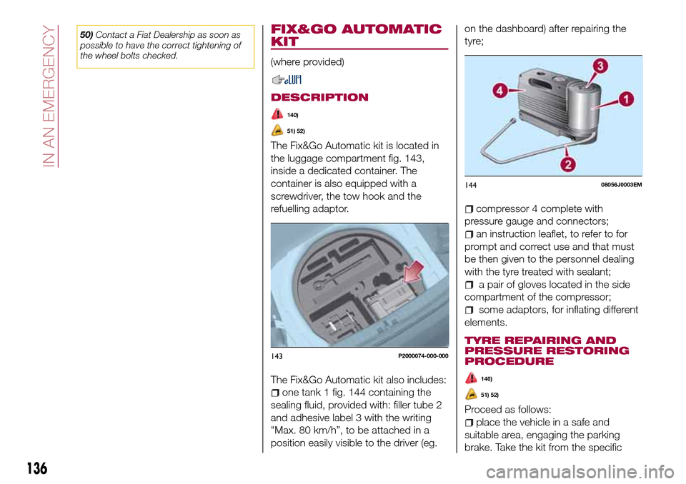
The Fix&Go Automatic kit is located in
the luggage compartment fig. 143,
inside a dedicated container. The
container is also equipped with a
screwdriver, the tow hook and the
refuelling adaptor.
The Fix&Go Automatic kit also includes:
one tank 1 fig. 144 containing the
sealing fluid, provided with: filler tube 2
and adhesive label 3 with the writing
"Max. 80 km/h”, to be attached in a
position easily visible to the driver (eg.on the dashboard) after repairing the
tyre;
compressor 4 complete with
pressure gauge and connectors;
an instruction leaflet, to refer to for
prompt and correct use and that must
be then given to the personnel dealing
with the tyre treated with sealant;
a pair of gloves located in the side
compartment of the compressor;
some adaptors, for inflating different
elements.
TYRE REPAIRING AND
PRESSURE RESTORING
PROCEDURE
140)
51) 52)
Proceed as follows:
place the vehicle in a safe and
suitable area, engaging the parking
brake. Take the kit from the specific
143P2000074-000-000
14408056J0003EM
136
IN AN EMERGENCY
Page 142 of 240
WARNING
141)Before opening the bonnet, make
sure that the engine is off and that the
ignition key is in the STOP position. Follow
the indications on the plate underneath the
bonnet. We recommend that you remove
the key from the ignition if other people
remain in the vehicle. The vehicle should
always be left after the key has been
removed or turned to the STOP position.
During refuelling, make sure that the engine
is off (and that the ignition key is in the
STOP position).
142)Do not get too close to the radiator
cooling fan: the electric fan may start;
danger of injury. Scarves, ties and other
loose clothing might be pulled by moving
parts.
143)Remove any metal objects (e.g. rings,
watches, bracelets), that might cause an
accidental electrical contact and cause
serious injury.
144)The batteries contain acid that can
burn skin or eyes. Batteries produce
hydrogen, which is easily flammable and
explosive. Therefore, keep away flames or
devices which may cause sparks.
IMPORTANT
53)Never use a fast battery-charger to
start the engine as this could damage the
electronic systems of your vehicle,
particularly the ignition and engine fuel
supply control units.54)Do not connect the cable to the
negative terminal (–) of the flat battery. The
following spark could lead to battery
explosion and cause serious harm. Only
use the specific earth point; do not use any
other exposed metallic part.
FUEL CUT-OFF
SYSTEM
DESCRIPTION
This intervenes in the case of an impact
causing:
the interruption of the fuel supply
with the engine consequently switching
off;
the automatic unlocking of the
doors;
turning on of the lights inside the
vehicle;
deactivation of climate control
system ventilation;
switching on of the hazard warning
lights (to deactivate the lights press the
button on the dashboard).
On some versions, the intervention of
the system is indicated by a message
shown on the display. In the same way,
a dedicated message on the display
warns the driver if system operation is
compromised.
IMPORTANT Carefully check the vehicle
for fuel leaks, for instance in the engine
compartment, under the vehicle or near
the tank area. After a collision, bring the
ignition device to STOP to prevent the
battery from running down.
140
IN AN EMERGENCY
Page 169 of 240
PLASTIC AND COATED
PARTS
72)
Clean interior plastic parts with a damp
cloth (if possible made from microfibre),
and a solution of water and neutral,
non-abrasive detergent.
To clean oily or persistent stains, use
specific products free from solvents and
designed to maintain the original
appearance and colour of the
components.
Remove any dust using a microfibre
cloth, if necessary moistened with
water. The use of paper tissues is not
recommended as these may leave
residues.
GENUINE LEATHER
PARTS
(where provided)
Use only water and mild soap to clean
these parts. Never use alcohol or
alcohol-based products.
Before using a specific product for
cleaning interiors, make sure that it
does not contain alcohol and/or alcohol
based substances.
WARNING
169)Never use flammable products, such
as petrol ether or rectified petrol to clean
the inside of the car. The electrostatic
charges which are generated by rubbing
during the cleaning operation may cause a
fire.
170)Do not keep aerosol cans in the car:
they might explode. Aerosol cans must not
be exposed to a temperature exceeding
50°C. When the vehicle is exposed to
sunlight, the internal temperature can
greatly exceed this value.
171)There must be no obstacles on the
floor underneath the pedals; make sure
that mats are always flat and do not
interfere with the pedals.
IMPORTANT
72)Never use alcohol, petrols and
derivatives to clean the dashboard and
instrument panel lens.
167
Page 171 of 240
IDENTIFICATION
DATA
VEHICLE IDENTIFICATION
NUMBER (VIN) PLATE
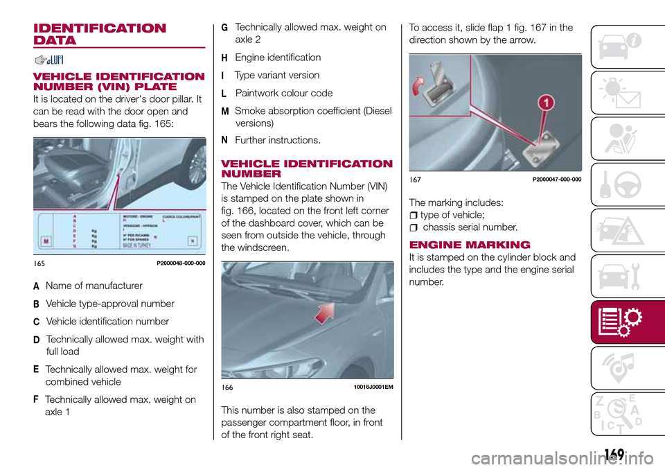
It is located on the driver's door pillar. It
can be read with the door open and
bears the following data fig. 165:
AName of manufacturer
BVehicle type-approval number
CVehicle identification number
DTechnically allowed max. weight with
full load
ETechnically allowed max. weight for
combined vehicle
FTechnically allowed max. weight on
axle 1
GTechnically allowed max. weight on
axle 2
HEngine identification
IType variant version
LPaintwork colour code
MSmoke absorption coefficient (Diesel
versions)
NFurther instructions.
VEHICLE IDENTIFICATION
NUMBER
The Vehicle Identification Number (VIN)
is stamped on the plate shown in
fig. 166, located on the front left corner
of the dashboard cover, which can be
seen from outside the vehicle, through
the windscreen.
This number is also stamped on the
passenger compartment floor, in front
of the front right seat.To access it, slide flap 1 fig. 167 in the
direction shown by the arrow.
The marking includes:
type of vehicle;
chassis serial number.
ENGINE MARKING
It is stamped on the cylinder block and
includes the type and the engine serial
number.165P2000048-000-000
16610016J0001EM
167P2000047-000-000
169
Page:
< prev 1-8 9-16 17-24