2016 FIAT TIPO 4DOORS stop start
[x] Cancel search: stop startPage 91 of 204

STOP/START
SYSTEM
(where provided)
The Stop/Start system automatically
stops the engine each time the vehicle
is stationary and starts it again when
the driver wants to move off.
In this way, the vehicle efficiency is
increased, by reducing consumption,
dangerous gas emissions and sound
pollution.
109)
26)
OPERATING MODE
Stopping the engine
Versions with mechanical gearbox
With the vehicle stopped, the engine
stops with gearbox in neutral and clutch
pedal released.
Versions with automatic
transmission
With vehicle at a standstill and brake
pedal pressed, the engine switches off
if the gear lever is in a position other
than R.
The system does not operate when the
gear lever is in R, for making parking
manoeuvres easier.In the event of stops uphill, engine
switching off is disabled to make the
"Hill Hold Control" function available
(works only with running engine).
NOTE the engine can only be
automatically stopped after exceeding a
speed of 10 km/h.
The
warning light on the instrument
panel switches on to signal that the
engine was stopped.
Restarting the engine
Versions with mechanical gearbox
To restart the engine, press the clutch
pedal or the accelerator pedal.
If the vehicle does not start when the
clutch is pressed, place the gear lever
in neutral and repeat the procedure. If
the problem persists, contact a Fiat
Dealership.
Versions with automatic
transmission
To restart the engine, release the brake
pedal.
With brake pressed, if the gear lever is
in automatic mode - D (Drive) - the
engine can be restarted by moving the
lever to R (Reverse) or "AutoStick".
With brake pressed, if the gear lever is
in "AutoStick" mode, the engine can be
restarted by moving the lever to R
(Reverse).When the engine has been stopped
automatically, keeping the brake pedal
pressed, the brake can be released
keeping the engine off by quickly
shifting the gear lever to P (Park).
To restart the engine, just move the
lever out of position P.SYSTEM MANUAL
ACTIVATION/
DEACTIVATION
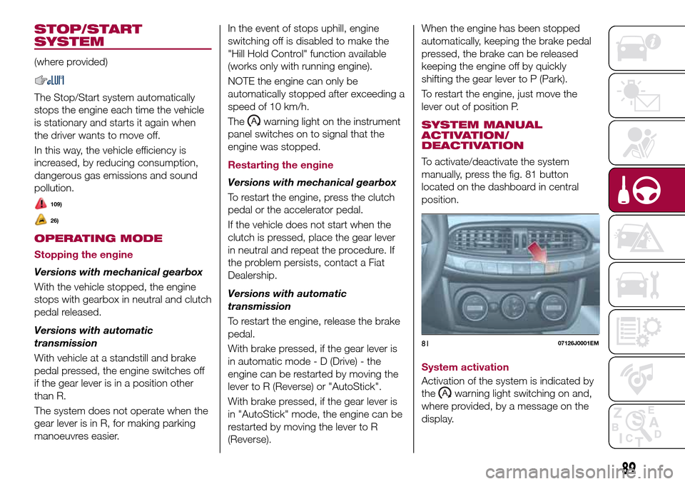
To activate/deactivate the system
manually, press the fig. 81 button
located on the dashboard in central
position.
System activation
Activation of the system is indicated by
the
warning light switching on and,
where provided, by a message on the
display.
8107126J0001EM
89
Page 92 of 204

System deactivation
Deactivation of the system is indicated
by the
warning light switching on
and, where provided, by a message on
the display.
SAFETY FUNCTIONS
When the engine is stopped through
the Stop/Start system, if the driver
releases their seat belt or opens the
driver's or passenger's door, the engine
can be restarted only by using the
ignition device.
This condition is indicated to the driver
both through a buzzer and a message
on the display.
WARNING
109)If the battery needs to be replaced,
always contact a Fiat Dealership. Replace
the battery with a new one of the same
type and specifications.
IMPORTANT
26)If the climate comfort is to be favoured,
the Start&Stop system can be deactivated,
for a continuous operation of the climate
control system.
ELECTRONIC
CRUISE CONTROL
(where provided)
This is an electronically controlled
driving assistance device that allows the
desired vehicle speed to be maintained,
without having to press the accelerator
pedal. This device can be used at a
speed above 30 km/h on long stretches
of dry, straight roads with few variations
(e.g. motorways).
It is therefore not recommended to use
this device on extra-urban roads with
traffic. Do not use it in town.
ACTIVATING THE DEVICE
110) 111) 112)
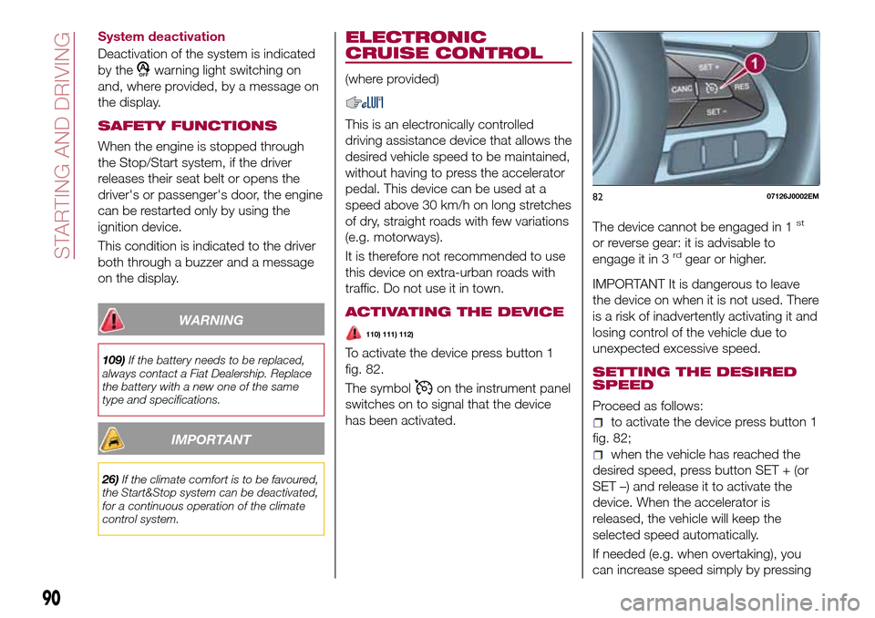
To activate the device press button 1
fig. 82.
The symbol
on the instrument panel
switches on to signal that the device
has been activated.The device cannot be engaged in 1
st
or reverse gear: it is advisable to
engage it in 3rdgear or higher.
IMPORTANT It is dangerous to leave
the device on when it is not used. There
is a risk of inadvertently activating it and
losing control of the vehicle due to
unexpected excessive speed.
SETTING THE DESIRED
SPEED
Proceed as follows:
to activate the device press button 1
fig. 82;
when the vehicle has reached the
desired speed, press button SET + (or
SET –) and release it to activate the
device. When the accelerator is
released, the vehicle will keep the
selected speed automatically.
If needed (e.g. when overtaking), you
can increase speed simply by pressing
8207126J0002EM
90
STARTING AND DRIVING
Page 94 of 204

distance from the obstacle behind the
vehicle decreases, the frequency of the
acoustic signal increases.
Acoustic signal
When reverse is engaged and there is
an obstacle behind the vehicle, an
acoustic signal is activated and the
signal varies as the distance of the
obstacle from the bumper varies.
The frequency of the acoustic signal:
increases as the distance between
the vehicle and the obstacle decreases;
becomes continuous when the
distance separating the vehicle from the
obstacle is less than about 30 cm;
is constant if the distance between
the vehicle and the obstacle is
unchanged. If this situation concerns
the side sensors, the signal will stop
after approximately 3 seconds to avoid,
for example, indications in the event of
manoeuvres along a wall.
stops immediately if the distance of
the obstacle increases.
When the system emits the acoustic
signal, the volume of theUconnect™
system (where provided) is
automatically lowered.
Detection distances
If several obstacles are detected by the
sensors, only the nearest one is
considered.Signals on the reconfigurable
multifunction display
The indications regarding the Park
Assist system are shown only on the
reconfigurable multifunction display and
only if the "Acoustic signal and display"
item in the "Settings" menu of the
Uconnect™system (where provided)
was previously selected (for more
information, see the description in the
dedicated chapter).
The system indicates the presence of
an obstacle by displaying a single arc in
one of the possible areas, in
accordance with the distance of the
object and the position in relation to the
vehicle. If the obstacle is detected in the
rear central area, a single arc will be
displayed as the obstacle approaches,
first constant, then flashing, in addition
to an acoustic signal.
OPERATION WITH A
TRAILER
The operation of the sensors is
automatically deactivated when the
trailer's electrical connection is inserted
in the vehicle's tow hook socket.
Sensors are reactivated on removing
the trailer's electrical connection. Before
using the Park Assist system, it is
recommended to remove the tow hook
ball assembly and the relevant
attachment from the vehicle. Failure tocomply with this prescription may
cause personal injuries or damage to
vehicles or obstacles since, when the
continuous acoustic signal is emitted,
the tow hook ball is already in a position
that is much closer to the obstacle than
the rear bumper. In addition, the
sensors may provide a false indication,
interpreting the tow hook ball assembly
and the relevant attachment as an
obstacle in the area behind the vehicle.
If you wish to leave the tow hook fitted
without towing a trailer, it is advisable to
contact a Fiat Dealership to have the
system updated and prevent detection
by the central sensors.
IMPORTANT NOTES
When parking, take the utmost care
over obstacles that may be above or
under the sensor. Objects close to the
vehicle are not detected under certain
circumstances and could therefore
cause damage to the vehicle or be
damaged.
Some conditions may influence the
performance of the parking system:
reduced sensor sensitivity and a
reduction in the parking assistance
system performance could be due to
the presence of: ice, snow, mud, paint,
etc. on the surface of the sensor;
the sensor may detect a
non-existent obstacle ("echo
92
STARTING AND DRIVING
Page 118 of 204

a visible position. Wear the protective
gloves provided. Remove the cap from
the valve of the punctured tyre and
connect and firmly tighten the
transparent tube of the sealing fluid 1
fig. 125;
ensure that the on-off button is in0
(OFF) position. If provided, open the
cover of the compressor 4 fig. 124 and
insert the electrical connector in the
12V socket of the vehicle fig. 126,
switch on the vehicle engine;
activate the compressor moving
on-off button toI(ON) position. When
the pressure gauge shows the vehicle
required pressure (see section “Wheels”
under “Technical data” chapter), switch
off the compressor moving on-off
button to0position. If after 5 minutes
from the compressor ignition, the
pressure gauge indicates a pressure
less than 1.8 bar / 26 psi, switch off thecompressor, disconnect the sealing
fluid tube from the tyre valve, re-screw
the valve cap and move the vehicle
about 10 meters to allow the
distribution of sealing fluid in the tyre.
Securely stop the vehicle and repeat
the operation above until reaching the
required pressure. If after other 5 min.
from the compressor ignition, the
pressure gauge still indicates a pressure
lower than 1.8 bar / 26 psi, the TYRE IS
TOO DAMAGED AND CANNOT BE
REPAIRED. Remove and place the kit in
the specific compartment and contact a
Fiat Dealership;
if the required pressure is reached,
restart driving. Do not exceed 80 km/h.
Avoid sudden acceleration or braking.
After driving for about 8 km / 5 miles,
place the vehicle in a safe and smooth
area, engaging the parking brake. Pick
up the kit, ensure the on-off button is in0position, insert the electrical
connector in the vehicle 12V socket.
Remove the cap from the valve of
repaired tyre, disconnect and pull out
the black inflation tube 1 fig. 127,
connect and block it with the stack to
the valve. Inspect the pressure gauge to
check the tyre pressure;
if the pressure indicated is lower than
1.8 bar / 26 psi, the TYRE IS TOO
DAMAGED AND CANNOT BE
REPAIRED. Remove and place the kit in
the specific compartment and contact a
Fiat Dealership;
if the pressure indicated is equal to or
higher than 1.8 bar / 26 psi, switch on
the compressor and reach the required
pressure. Disconnect and replace the
kit in the specific compartment.
Carefully drive and reach the Fiat
Dealership as soon as possible;
12508056J0004EM
12608056J0002EM
12708056J0006EM
116
IN AN EMERGENCY
Page 119 of 204

WARNING
133)The information required by the
applicable regulation is indicated on the
Fix&Go kit package label. Compliance with
the indications on the label is an essential
condition to ensure the safety and the
effectiveness of the Fix&Go kit. Carefully
read the label before use, avoid improper
use. Fix&Go is subject to expiration and
must be replaced periodically. The kit
should be used by adults and cannot be
used by children.
IMPORTANT
38)Show the package and the label to the
personnel charged with handling the tyre
treated with the tyre repair kit.
39)Fix&Go provides a temporary repair,
therefore the tyre must be examined and
repaired by a specialist as soon as
possible. The sealing fluid is effective at
temperatures between -40°C and +50°C. It
is possible to repair tyres which have been
damaged on tread up to a diameter of
4mm; however, tyres damaged on their
side cannot be repaired. Before using
Fix&Go kit, ensure that the tyre isn't
excessively damaged and that the rim is in
good condition, otherwise do not use it and
contact a Fiat Dealership. Do not remove
foreign bodies from the tyre. Do not let the
compressor turned on for more than 20
consecutive minutes - overheating hazard.
EMERGENCY
STARTING
If the battery is flat, a jump starting can
be performed using the battery and the
cables of another vehicle, or using an
auxiliary battery. In all cases, the battery
used must have a capacity equal to or
a little higher than the flat one.
40)
IMPORTANT NOTES
Do not use an auxiliary battery or any
other source of external supply with a
voltage above 12 V: the battery, the
starter, the alternator and the electrical
system of the vehicle could be
damaged.
Do not attempt jump starting if the
battery is frozen. The battery could
break and explode!
PREPARATION TO JUMP
STARTING
The vehicle battery is located in the
engine compartment, behind the left
light cluster.
134) 135) 136) 137)
IMPORTANT The positive terminal (+) of
the battery is shielded by a protective
element. Raise it to access the terminal.
Proceed as follows:
operate the parking brake, move the
lever to P (Park), for versions equipped
with automatic transmission (if present),
or neutral, for versions with manual
gearbox, then set the ignition device to
STOP;
switch off all the other electrical
devices in the vehicle;
should you be using the battery of
another vehicle, park the other vehicle
within the range of the cables used for
the connection, operate the parking
brake and ensure that its ignition is off.
IMPORTANT Never connect the
negative terminals of the two batteries
directly! If the auxiliary battery is
installed on another vehicle, check that
there is no accidental contact of metal
parts between the two vehicles, since
an earth connection may result, with
the risk of serious injury to any people
who may be nearby.
IMPORTANT If the procedure below is
carried out incorrectly, it can cause
severe injury to people or damage the
recharging system of one or both
vehicles. Carefully follow the
instructions given below.
Cable connection
41)
Proceed as follows to carry out a jump
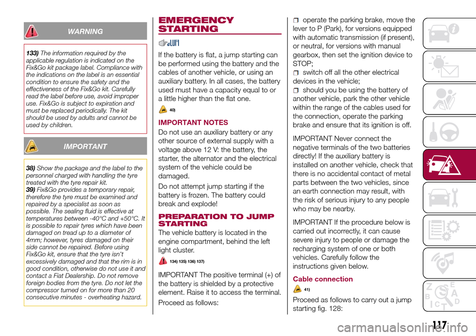
starting fig. 128:
117
Page 120 of 204

connect one end of the cable used
for positive (+) to the positive terminal
(+) of the vehicle with flat battery;
connect the other end of the cable
used for positive (+) to the positive
terminal (+) of the auxiliary battery;
connect one end of the cable used
for negative (–) to the negative terminal
(–) of the auxiliary battery;
connect the other end of the cable
used for negative (–) to an engine earth
(a visible metal part of the engine or
gearbox/transmission of the vehicle
with flat battery) away from the battery
and the fuel injection system;
start the vehicle engine with the
auxiliary battery, let it run for a few
minutes at idling. Start the engine of the
vehicle with flat battery.Cable disconnection
Once the engine is started, remove the
leads, reversing the order above.
If after a few attempts the engine does
not start, do not persist but contact a
Fiat Dealership.
If it is often necessary to perform a
jump starting, have the vehicle battery
and the recharging system checked by
a Fiat Dealership.
WARNING
134)Before opening the bonnet, make
sure that the engine is off and that the
ignition key is in the STOP position. Follow
the indications on the plate underneath the
bonnet. We recommend that you remove
the key from the ignition if other people
remain in the vehicle. The vehicle should
always be left after the key has been
removed or turned to the STOP position.
During refuelling, make sure that the engine
is off (and that the ignition key is in the
STOP position).
135)Do not get too close to the radiator
cooling fan: the electric fan may start;
danger of injury. Scarves, ties and other
loose clothing might be pulled by moving
parts.
136)Remove any metal objects (e.g. rings,
watches, bracelets), that might cause an
accidental electrical contact and cause
serious injury.137)The batteries contain acid that can
burn skin or eyes. Batteries produce
hydrogen, which is easily flammable and
explosive. Therefore, keep away flames or
devices which may cause sparks.
IMPORTANT
40)Never use a fast battery-charger to
start the engine as this could damage the
electronic systems of your vehicle,
particularly the ignition and engine fuel
supply control units.
41)Do not connect the cable to the
negative terminal (–) of the flat battery. The
following spark could lead to battery
explosion and cause serious harm. Only
use the specific earth point; do not use any
other exposed metallic part.
12808066J0003EM
118
IN AN EMERGENCY
Page 121 of 204

FUEL CUT-OFF
SYSTEM
DESCRIPTION
This intervenes in the case of an impact
causing:
the interruption of the fuel supply
with the engine consequently switching
off;
the automatic unlocking of the
doors;
turning on of the lights inside the
vehicle;
deactivation of climate control
system ventilation;
switching on of the hazard warning
lights (to deactivate the lights press the
button on the dashboard).
On some versions, the intervention of
the system is indicated by a message
shown on the display. In the same way,
a dedicated message on the display
warns the driver if system operation is
compromised.
IMPORTANT Carefully check the vehicle
for fuel leaks, for instance in the engine
compartment, under the vehicle or near
the tank area. After a collision, bring the
ignition device to STOP to prevent the
battery from running down.FUEL CUT-OFF SYSTEM
RESET
To restore correct operation of the
vehicle, carry out the following
procedure (this procedure must be
started and completed within less than
1 minute):
138)
Operations to be carried out
With direction indicator lever in neutral
position, bring the ignition device to STOP
Bring the ignition device to MAR
Activate the right direction indicator
Activate the left direction indicator
Activate the right direction indicator
Activate the left direction indicator
Deactivate the left direction indicator
Bring the ignition device to STOP
Bring the ignition device to MAR
WARNING
138)If, after an impact, you smell fuel or
notice leaks from the fuel system, do not
reactivate the system to avoid the risk of
fire.
AUTOMATIC
TRANSMISSION
Lever release
In the event of a fault, to move the gear
lever from P (Park), proceed as follows:
stop the engine;
engage the parking brake;
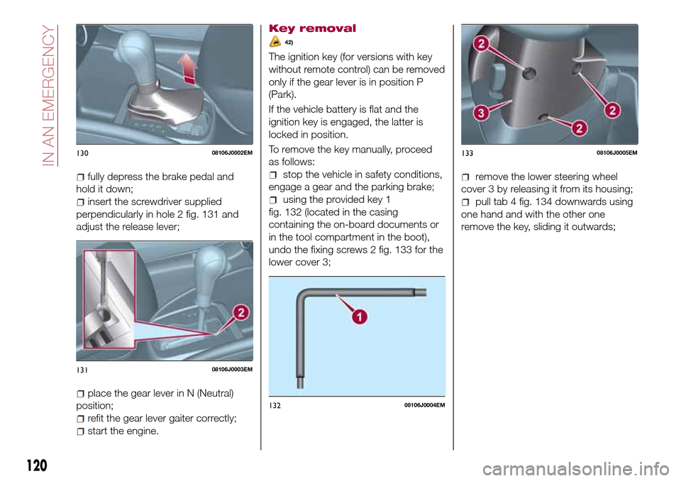
working carefully in the point
indicated by the arrow, remove the gear
lever gaiter 1 fig. 129 (also see
fig. 130 );
12908106J0001EM
119
Page 122 of 204

fully depress the brake pedal and
hold it down;
insert the screwdriver supplied
perpendicularly in hole 2 fig. 131 and
adjust the release lever;
place the gear lever in N (Neutral)
position;
refit the gear lever gaiter correctly;
start the engine.
Key removal
42)
The ignition key (for versions with key
without remote control) can be removed
only if the gear lever is in position P
(Park).
If the vehicle battery is flat and the
ignition key is engaged, the latter is
locked in position.
To remove the key manually, proceed
as follows:
stop the vehicle in safety conditions,
engage a gear and the parking brake;
using the provided key 1
fig. 132 (located in the casing
containing the on-board documents or
in the tool compartment in the boot),
undo the fixing screws 2 fig. 133 for the
lower cover 3;
remove the lower steering wheel
cover 3 by releasing it from its housing;
pull tab 4 fig. 134 downwards using
one hand and with the other one
remove the key, sliding it outwards;
13008106J0002EM
13108106J0003EM
13208106J0004EM
13308106J0005EM
120
IN AN EMERGENCY