2016 FIAT TIPO 4DOORS lock
[x] Cancel search: lockPage 64 of 204
OCCUPANT
PROTECTION
SYSTEMS
Some of the most important safety
equipment of the vehicle comprise the
following protection systems:
seat belts;
SBR (Seat Belt Reminder) system;
head restraints;
child restraint systems;
Front air bags, side air bags (if
present) and drop down air bags (if
present).
Read the information given the following
pages with the utmost care. It is of
fundamental importance that the
protection systems are used in the
correct way to guarantee the maximum
possible safety level for the driver and
the passengers.
For the description of the head restraint
adjustment see the "Head restraints"
paragraph in the "Knowing your vehicle"
chapter.
SEAT BELTS
All vehicle seats are equipped with seat
belts with three anchor points and a
retractor.
The retractor mechanism operates
locking the belt in the event of sharp
braking or strong deceleration due to
an impact. This allows the belt strap to
slide freely and to adapt to the body of
the occupant. In the event of an
accident, the belt will lock reducing the
risk of impact inside the passenger
compartment and of being projected
outside the vehicle.
The driver is responsible for respecting,
and ensuring that all the other
occupants of the vehicle also respect,
the local laws in force in relation to the
use of the seat belts.
Always fasten the seat belts before
setting off.
USING THE SEAT BELTS
The seat belt should be worn keeping
the chest straight and rested against
the backrest.
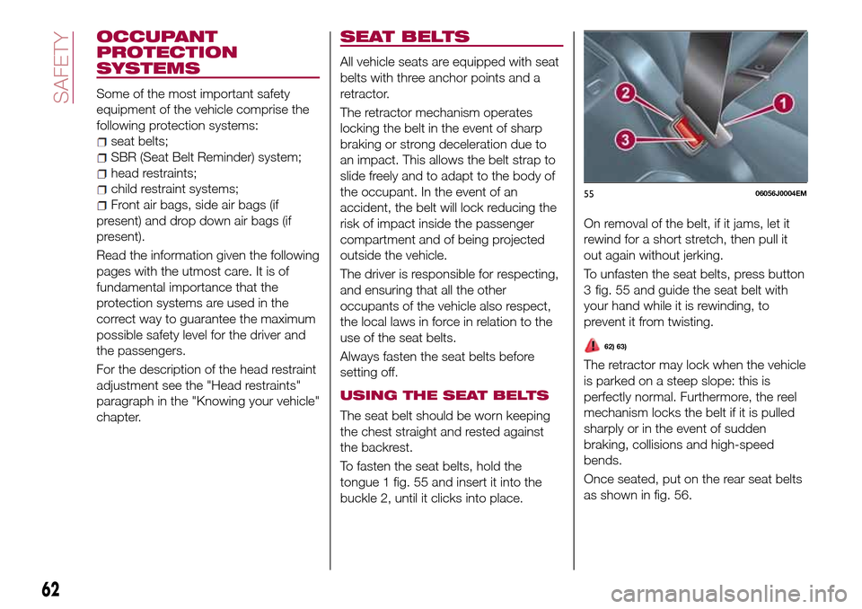
To fasten the seat belts, hold the
tongue 1 fig. 55 and insert it into the
buckle 2, until it clicks into place.On removal of the belt, if it jams, let it
rewind for a short stretch, then pull it
out again without jerking.
To unfasten the seat belts, press button
fig. 55 and guide the seat belt with
your hand while it is rewinding, to
prevent it from twisting.
62) 63)
The retractor may lock when the vehicle
is parked on a steep slope: this is
perfectly normal. Furthermore, the reel
mechanism locks the belt if it is pulled
sharply or in the event of sudden
braking, collisions and high-speed
bends.
Once seated, put on the rear seat belts
as shown in fig. 56.
5506056J0004EM
62
SAFETY
3
Page 65 of 204
Seat belt of the rear central seat
Unlike other seat belts, this one has two
buckles and two metal tongues. In this
manner, release the seat belt to recline
a larger portion (2/3) of the backrest
(see the "Seats" chapter for more
information).
To fasten the seat belt follow the below
procedure:
Place yourself on the central seat
and normally pull out the seat belt from
top rewinder without twisting it;
In the left buckle (without the red
unlock button on the slot) insert the first
tongue which is located at the end of
the diagonal section of the seat belt;
In the right buckle insert the tongue
which is located at the end of the
abdominal section of the belt.
To unfasten the seat belt, unlock the
tongue of the abdominal section
pressing the red button.
IMPORTANT With the rear seat
backrest in vertical position, ensure that
the tongue which is located at the end
of the diagonal section of the central
seat belt is always properly hooked to
the left buckle (without the red unlock
button on the slot).
ADJUSTING THE SEAT
BELT HEIGHT
64) 65)
Three different adjustments in height are
provided.
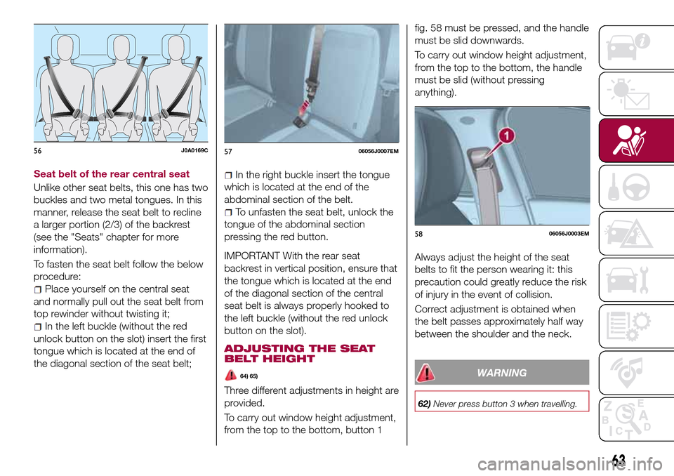
To carry out window height adjustment,
from the top to the bottom, button 1fig. 58 must be pressed, and the handle
must be slid downwards.
To carry out window height adjustment,
from the top to the bottom, the handle
must be slid (without pressing
anything).
Always adjust the height of the seat
belts to fit the person wearing it: this
precaution could greatly reduce the risk
of injury in the event of collision.
Correct adjustment is obtained when
the belt passes approximately half way
between the shoulder and the neck.
WARNING
62)Never press button 3 when travelling.
56J0A0169C5706056J0007EM
5806056J0003EM
63
Page 66 of 204
63)Remember that, in the event of an
accident, the rear seat passengers not
wearing seat belts are exposed to a very
serious risk and also represent a serious
danger for the front seat occupants.
64)Make height adjustment of the seat
belts when the car is stationary.
65)After the height adjustment, always
check that the grip is locked in one of the
preset positions. To do this, with buttons 1
released, exert further pressure
downwards to allow the locking device to
click if the grip has not been released in
one of the possible positions.SBR (SEAT BELT
REMINDER) SYSTEM
(for versions/markets, where provided)
The SBR system informs the driver that
his/her safety belt is not fastened.
The system signals unfastened seat
belts with visual warnings ( warning light
on in the instrument panel) and an
acoustic signal (see the following
paragraphs).
NOTE To deactivate the acoustic
warning permanently go to a Fiat
Dealership. The acoustic warning can
be reactivated at any time through the
display Menu (see the "Display"
paragraph in the “Knowing the
instrument panel” chapter).
FRONT SEAT BELT
WARNING LIGHT
BEHAVIOUR
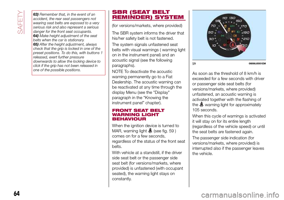
When the ignition device is turned to
MAR, warning light
(see fig. 59 )
comes on for a few seconds,
regardless of the status of the front seat
belts.
With vehicle at a standstill, if the driver
side seat belt or the passenger side
seat belt (for versions/markets, where
provided) is unfastened (with occupant
seated), the warning light stays on
constantly.As soon as the threshold of 8 km/h is
exceeded for a few seconds with driver
or passenger side seat belts (for
versions/markets, where provided)
unfastened, an acoustic warning is
activated together with the flashing of
the
warning light for approximately
105 seconds.
When this cycle of warnings is activated
it will stay on for its entire length
(regardless of the vehicle speed) or until
the seat belts are fastened again.
The passenger side indication (for
versions/markets, where provided) is
interrupted also if the passenger leaves
the vehicle.
5906066J0001EM
64
SAFETY
Page 90 of 204
bring the transmission lever to P
(Park);
bring the ignition device to STOP;
wait for about 10 seconds, then
restart the engine;
select the desired gear: correct
transmission operation should be
restored.
IMPORTANT In the event of a
temporary failure it is in any case
recommended to contact a Fiat
Dealership as soon as possible.
GEAR ENGAGEMENT
DISABLING SYSTEM
WITHOUT BRAKE PEDAL
PRESSED
This system prevents you from moving
the gear lever from position P (Park)
and N (Neutral) if the brake pedal has
not been previously depressed.
To bring the gear lever to a position
other than P (Park) or from N (Neutral)
to R (Reverse), the ignition device must
be in position MAR (engine on or off)
and the brake pedal must be
depressed. Button 1 fig. 80 on the gear
lever knob must also be pressed. To
move the lever from position N (Neutral)
to position D (Drive, automatic forward
gear), you need to press the brake
pedal.
To facilitate parking manoeuvres, move
the lever from D to R (and vice versa)without pressing the brake if the lever
does not pass through the N position.
The lever will remain locked in the P
position in case of faults or flat battery.
See the “Automatic transmission” in the
“In an emergency” chapter for how to
release the lever manually.
WARNING
106)Never use position P (Park) instead of
the parking brake. Always engage the
parking brake when parking the vehicle to
avoid the accidental movement of the
vehicle.
107)If the P (Park) position is not engaged,
the vehicle could move and injure people.
Before leaving the vehicle, make sure that
the gear lever is in position P and that the
parking brake is engaged.
108)Do not shift the gear lever to N
(Neutral) and do not stop the engine when
driving on a downhill road. This type of
driving is dangerous and reduces the
possibility of intervening in the case of
variation of the road traffic or surface. You
risk losing control of your vehicle and
causing accidents.
IMPORTANT
24)Before moving the gear lever from
position P (Park), bring the ignition device
to position MAR and press the brake pedal.
Otherwise, the gear lever may get
damaged.25)Engage reverse only with the car
stationary, engine at idling speed and
accelerator fully released.
88
STARTING AND DRIVING
Page 98 of 204
REFUELLING THE
VEHICLE
117) 118) 119)
PETROL ENGINES
Only use unleaded petrol with a number
of octanes (R.O.N.) not lower than 95
(EN228 specification).
DIESEL ENGINES
31)
Only use Diesel for motor vehicles
(EN590 specification).
When using or parking the vehicle for a
long time in the mountains or cold
areas, it is advisable to refuel using
locally available Diesel. In this case, it is
also advisable to keep the tank over
50% full.
REFUELLING
PROCEDURE
"Capless Fuel" is a device at the
opening for the fuel tank which opens
and recloses automatically when the
fuel supply gun is introduced/removed.
The "Capless Fuel" device is provided
with an inhibitor which prevents
refuelling with incorrect fuel.
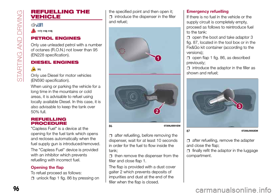
Opening the flap
To refuel proceed as follows:
unlock flap 1 fig. 86 by pressing onthe specified point and then open it;
introduce the dispenser in the filler
and refuel;
after refuelling, before removing the
dispenser, wait for at least 10 seconds
in order for the fuel to flow inside the
tank;
then remove the dispenser from the
filler and close flap 1.
The flap is provided with a dust cover
gaiter 2 which prevents deposits of
impurities and dust at the end of the
filler when the flap is closed.Emergency refuelling
If there is no fuel in the vehicle or the
supply circuit is completely empty,
proceed as follows to reintroduce fuel
to the tank:
open the boot and take adaptor 3
fig. 87, located in the tool box or in the
Fix&Go kit container (according to the
versions);
open flap 1 fig. 86, as described
previously;
introduce the adaptor in the filler as
shown and refuel;
after refuelling, remove the adapter
and close the flap;
finally refit the adaptor in the luggage
compartment.
8607206J0001EM
8707206J0002EM
96
STARTING AND DRIVING
Page 102 of 204

TYPES OF BULBS
The vehicle is equipped with the following bulbs
Glass bulbs (type 1): they are press-fitted. Pull to extract.
Bayonet-type bulbs (type 2): to remove them from their holder,
press the bulb and turn it anticlockwise, then extract it.
Halogen bulbs (type 3): to remove the bulb, pull the connector and
extract it.
Halogen bulbs (type 4): to remove the bulb, turn it anticlockwise.
100
IN AN EMERGENCY
Page 104 of 204

REPLACING AN
EXTERNAL BULB
Front bulb position
1. Dipped headlights
2. Fog lights
3. Main beam headlights/Daytime
running lights (DRL)
4. Direction indicator.
Main beam headlights/Daytime
running lights (DRL)
To replace the bulb 3 fig. 89, proceed
as follows:
working from inside the engine
compartment, remove rubber cap 1
fig. 90;
rotate the bulb-bulb holder assembly
anticlockwise and extract it;
disconnect the electrical connector
and replace the bulb-bulb holder
assembly 2;
reconnect the electrical connector to
the new assembly;
then insert the assembly in its
housing and turn it clockwise, making
sure that it is locked correctly;
refit the rubber cap 1.
IMPORTANT Only replace the bulb
when the engine is off. Also ensure that
the engine is cold, to prevent the risk of
burns.
Dipped headlights
Right headlight
To replace the bulb 1 fig. 89, proceed
as follows:
steer the vehicle wheels completely
inwards;
adjust the tabs indicated in the figure
fig. 91 and remove the flap;
remove the rubber plug
disconnect the electrical connector;
extract the bulb, releasing it from the
retaining springs;
replace the new bulb and carry out
the procedure described previously in
reverse.
Left headlight
working from inside the engine
compartment, remove the rubber cap
from the dipped beam headlight bulb 1
fig. 89;
extract the bulb, releasing it from the
retaining springs;
disconnect the electrical connector
and replace the bulb 1 fig. 89;
reconnect the electrical connector to
the new bulb;
8908026J0002EM
9008026J0025EM9108026J0004EM
102
IN AN EMERGENCY
Page 105 of 204

reposition the assembly in the seat;
refit the rubber cap.
IMPORTANT Only replace the bulb
when the engine is off. Also ensure that
the engine is cold, to prevent the risk of
burns.
Front direction indicators
To replace the bulb 4 fig. 89, proceed
as follows:
use the provided screwdriver to lift
the indicated pins and remove the
cover 1 fig. 92;
rotate the bulb-bulb holder assembly
anticlockwise;
replace the "bayonet-fitted" bulb;
then insert the bulb and bulb holder
assembly in its housing and turn it
clockwise, making sure that it is locked
correctly;
refit the cover and block it by placing
its pins in their seats.
Front fog lights
To replace the bulbs, proceed as
follows:
steer the vehicle wheels completely
inwards;
adjust the tabs indicated in
fig. 93 and remove the flap;
turn the bulb-bulb holder assembly 1fig. 94 anticlockwise and then remove it
sliding it outwards;
disconnect the electrical connector;
reconnect the connector to the new
assembly: then insert it, turning it
clockwise, ensuring that it locks
correctly;
finally, refit the inspection lid.
Side direction indicators
To replace the bulb, proceed as follows:
adjust the lens 1 fig. 95 to compress
in the internal clip 2, then pull the
cluster outwards;
turn the bulb holder 3 anticlockwise,
extract the press-fitted bulb 4 and
replace it;
refit the bulb holder 3 in the lens and
turn it clockwise;
refit the cluster making sure that the
internal clip 2 clicks into position.
9208026J0011EM
9308026J0012EM
9408026J0016EM
9508026J0005EM
103