2016 FIAT TIPO 4DOORS dashboard
[x] Cancel search: dashboardPage 91 of 204
STOP/START
SYSTEM
(where provided)
The Stop/Start system automatically
stops the engine each time the vehicle
is stationary and starts it again when
the driver wants to move off.
In this way, the vehicle efficiency is
increased, by reducing consumption,
dangerous gas emissions and sound
pollution.
109)
26)
OPERATING MODE
Stopping the engine
Versions with mechanical gearbox
With the vehicle stopped, the engine
stops with gearbox in neutral and clutch
pedal released.
Versions with automatic
transmission
With vehicle at a standstill and brake
pedal pressed, the engine switches off
if the gear lever is in a position other
than R.
The system does not operate when the
gear lever is in R, for making parking
manoeuvres easier.In the event of stops uphill, engine
switching off is disabled to make the
"Hill Hold Control" function available
(works only with running engine).
NOTE the engine can only be
automatically stopped after exceeding a
speed of 10 km/h.
The
warning light on the instrument
panel switches on to signal that the
engine was stopped.
Restarting the engine
Versions with mechanical gearbox
To restart the engine, press the clutch
pedal or the accelerator pedal.
If the vehicle does not start when the
clutch is pressed, place the gear lever
in neutral and repeat the procedure. If
the problem persists, contact a Fiat
Dealership.
Versions with automatic
transmission
To restart the engine, release the brake
pedal.
With brake pressed, if the gear lever is
in automatic mode - D (Drive) - the
engine can be restarted by moving the
lever to R (Reverse) or "AutoStick".
With brake pressed, if the gear lever is
in "AutoStick" mode, the engine can be
restarted by moving the lever to R
(Reverse).When the engine has been stopped
automatically, keeping the brake pedal
pressed, the brake can be released
keeping the engine off by quickly
shifting the gear lever to P (Park).
To restart the engine, just move the
lever out of position P.SYSTEM MANUAL
ACTIVATION/
DEACTIVATION
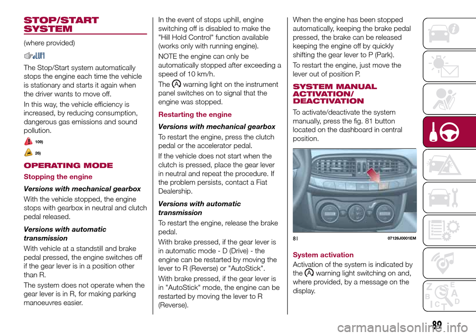
To activate/deactivate the system
manually, press the fig. 81 button
located on the dashboard in central
position.
System activation
Activation of the system is indicated by
the
warning light switching on and,
where provided, by a message on the
display.
8107126J0001EM
89
Page 108 of 204
IMPORTANT
32)Halogen bulbs must be handled
holding the metallic part only. Touching the
transparent part of the bulb with your
fingers may reduce the intensity of the
emitted light and even reduce the lifespan
of the bulb. In the event of accidental
contact, wipe the bulb with a cloth
moistened with alcohol and let the bulb dry.
REPLACING FUSES
GENERAL
123) 124) 125) 126)
33)
Fuses protect the electrical system:
they intervene (blow) in the event of a
failure or improper action on the
system.
Fuse extracting pliers
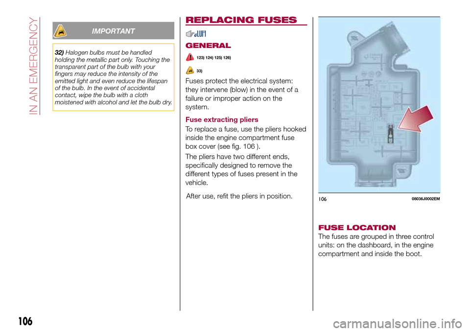
To replace a fuse, use the pliers hooked
inside the engine compartment fuse
box cover (see fig. 106 ).
The pliers have two different ends,
specifically designed to remove the
different types of fuses present in the
vehicle.
After use, refit the pliers in position.
FUSE LOCATION
The fuses are grouped in three control
units: on the dashboard, in the engine
compartment and inside the boot.
10608036J0002EM
106
IN AN EMERGENCY
Page 109 of 204
ENGINE COMPARTMENT
FUSE BOX
34)
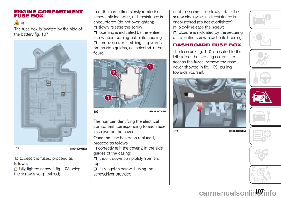
The fuse box is located by the side of
the battery fig. 107.
To access the fuses, proceed as
follows:
fully tighten screw 1 fig. 108 using
the screwdriver provided;
at the same time slowly rotate the
screw anticlockwise, until resistance is
encountered (do not overtighten);
slowly release the screw;
opening is indicated by the entire
screw head coming out of its housing;
remove cover 2, sliding it upwards
on the side guides, as indicated in the
figure.
The number identifying the electrical
component corresponding to each fuse
is shown on the cover.
Once the fuse has been replaced,
proceed as follows:
correctly refit the cover 2 in the side
guides of the casing;
slide it down completely from the
top;
fully tighten screw 1 using the
screwdriver provided;
at the same time slowly rotate the
screw clockwise, until resistance is
encountered (do not overtighten);
slowly release the screw;
closure is indicated by the securing
of the entire screw head in its housing.
DASHBOARD FUSE BOX
The fuse box fig. 110 is located to the
left side of the steering column. To
access the fuses, remove the snap
cover showed in fig. 109, pulling
towards yourself.
10708036J0005EM
10808036J0006EM
10906106J0005EM
107
Page 111 of 204
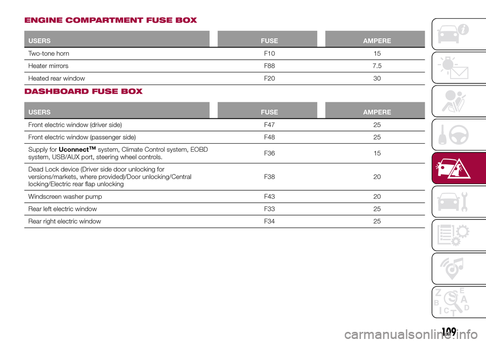
ENGINE COMPARTMENT FUSE BOX
USERSFUSE AMPERE
Two-tone horn F10 15
Heater mirrors F88 7.5
Heated rear window F20 30
DASHBOARD FUSE BOX
USERSFUSE AMPERE
Front electric window (driver side) F47 25
Front electric window (passenger side) F48 25
Supply forUconnect
™system, Climate Control system, EOBD
system, USB/AUX port, steering wheel controls.F36 15
Dead Lock device (Driver side door unlocking for
versions/markets, where provided)/Door unlocking/Central
locking/Electric rear flap unlockingF38 20
Windscreen washer pump F43 20
Rear left electric window F33 25
Rear right electric window F34 25
109
Page 117 of 204
37)When turning the jack handle make
sure that it can turn freely without scraping
your hand against the ground. The moving
components of the jack ("worm screw" and
joints) can also cause injuries: avoid
touching them. If you come into contact
with lubricating grease, clean yourself
thoroughly.FIX&GO AUTOMATIC
KIT
(where provided)
DESCRIPTION
133)
38) 39)
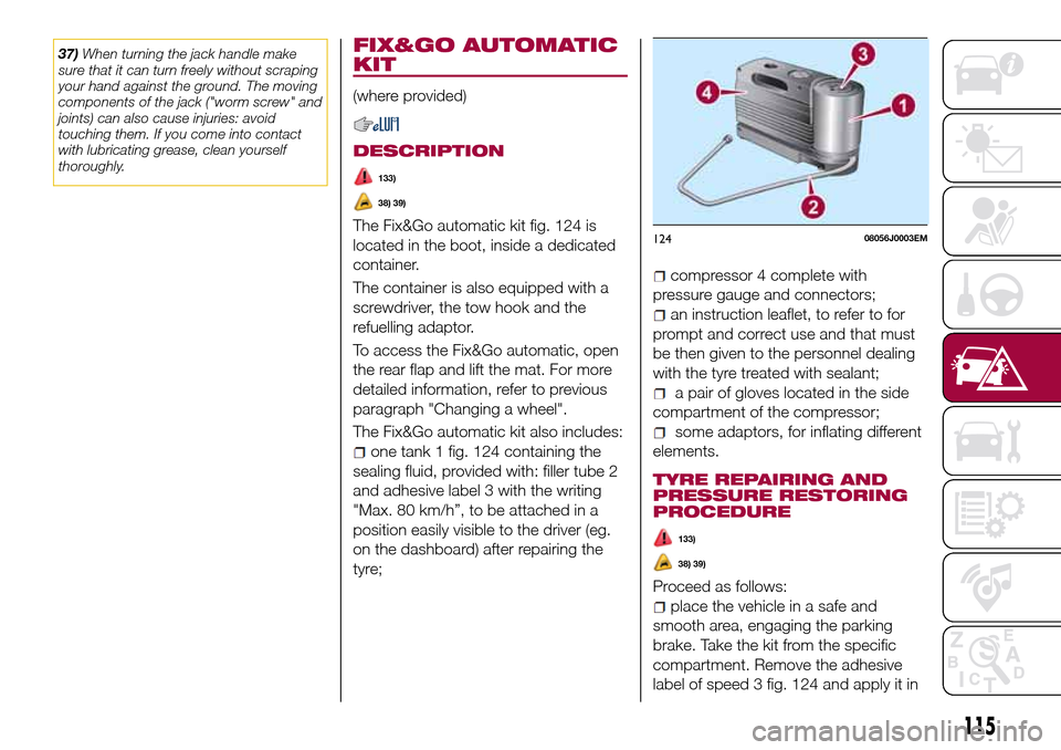
The Fix&Go automatic kit fig. 124 is
located in the boot, inside a dedicated
container.
The container is also equipped with a
screwdriver, the tow hook and the
refuelling adaptor.
To access the Fix&Go automatic, open
the rear flap and lift the mat. For more
detailed information, refer to previous
paragraph "Changing a wheel".
The Fix&Go automatic kit also includes:
one tank 1 fig. 124 containing the
sealing fluid, provided with: filler tube 2
and adhesive label 3 with the writing
"Max. 80 km/h”, to be attached in a
position easily visible to the driver (eg.
on the dashboard) after repairing the
tyre;
compressor 4 complete with
pressure gauge and connectors;
an instruction leaflet, to refer to for
prompt and correct use and that must
be then given to the personnel dealing
with the tyre treated with sealant;
a pair of gloves located in the side
compartment of the compressor;
some adaptors, for inflating different
elements.
TYRE REPAIRING AND
PRESSURE RESTORING
PROCEDURE
133)
38) 39)
Proceed as follows:
place the vehicle in a safe and
smooth area, engaging the parking
brake. Take the kit from the specific
compartment. Remove the adhesive
label of speed 3 fig. 124 and apply it in
12408056J0003EM
115
Page 121 of 204

FUEL CUT-OFF
SYSTEM
DESCRIPTION
This intervenes in the case of an impact
causing:
the interruption of the fuel supply
with the engine consequently switching
off;
the automatic unlocking of the
doors;
turning on of the lights inside the
vehicle;
deactivation of climate control
system ventilation;
switching on of the hazard warning
lights (to deactivate the lights press the
button on the dashboard).
On some versions, the intervention of
the system is indicated by a message
shown on the display. In the same way,
a dedicated message on the display
warns the driver if system operation is
compromised.
IMPORTANT Carefully check the vehicle
for fuel leaks, for instance in the engine
compartment, under the vehicle or near
the tank area. After a collision, bring the
ignition device to STOP to prevent the
battery from running down.FUEL CUT-OFF SYSTEM
RESET
To restore correct operation of the
vehicle, carry out the following
procedure (this procedure must be
started and completed within less than
1 minute):
138)
Operations to be carried out
With direction indicator lever in neutral
position, bring the ignition device to STOP
Bring the ignition device to MAR
Activate the right direction indicator
Activate the left direction indicator
Activate the right direction indicator
Activate the left direction indicator
Deactivate the left direction indicator
Bring the ignition device to STOP
Bring the ignition device to MAR
WARNING
138)If, after an impact, you smell fuel or
notice leaks from the fuel system, do not
reactivate the system to avoid the risk of
fire.
AUTOMATIC
TRANSMISSION
Lever release
In the event of a fault, to move the gear
lever from P (Park), proceed as follows:
stop the engine;
engage the parking brake;
working carefully in the point
indicated by the arrow, remove the gear
lever gaiter 1 fig. 129 (also see
fig. 130 );
12908106J0001EM
119
Page 149 of 204
WARNING
161)Never use flammable products, such
as petrol ether or rectified petrol to clean
the inside of the car. The electrostatic
charges which are generated by rubbing
during the cleaning operation may cause a
fire.
162)Do not keep aerosol cans in the car:
they might explode. Aerosol cans must not
be exposed to a temperature exceeding
50°C. When the vehicle is exposed to
sunlight, the internal temperature can
greatly exceed this value.
163)There must be no obstacles on the
floor underneath the pedals; make sure
that mats are always flat and do not
interfere with the pedals.
IMPORTANT
61)Never use alcohol, petrols and
derivatives to clean the dashboard and
instrument panel lens.
147
Page 151 of 204

IDENTIFICATION
DATA
VEHICLE IDENTIFICATION
NUMBER (VIN) PLATE
It is located on the driver's door pillar. It
can be read with the door open and
shows the following data fig. 146:
AName of manufacturer
BVehicle type-approval number
CVehicle identification number
DTechnically allowed max. weight with
full load
ETechnically allowed max. weight for
combined vehicle
FTechnically allowed max. weight on
axle 1
GTechnically allowed max. weight on
axle 2
HEngine identification
IType variant version
LPaintwork colour code
MSmoke absorption coefficient (Diesel
versions)
NFurther instructions.
VEHICLE IDENTIFICATION
NUMBER
The Vehicle Identification Number (VIN)
is stamped on the plate shown in
fig. 147, located on the front left corner
of the dashboard cover, which can be
seen from outside the vehicle, through
the windscreen.
This number is also stamped on the
passenger compartment floor, in front
of the front right seat.To access it, lift the pre-sheared part of
the fabric fig. 148 in the direction
indicated by the arrow.
The marking includes:
type of vehicle;
chassis serial number.
ENGINE MARKING
It is stamped on the cylinder block and
includes the type and the engine serial
number.14610016J0003EM
14710016J0001EM
14810016J0002EM
149