Page 159 of 323

REPLACING AN
EXTERIOR BULB
For the type of bulb and relevant power
rating, see “Changing a bulb”.
FRONT LIGHT CLUSTERS
The front light clusters contain side
light, daytime running light, dipped,
main beam and direction indicator
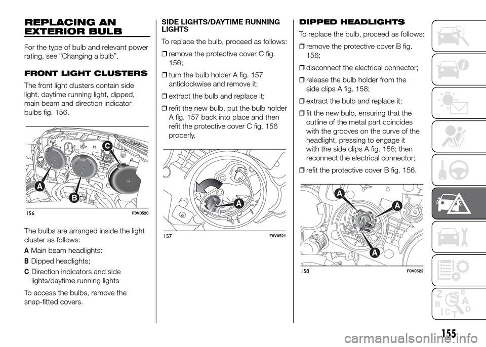
bulbs fig. 156.
The bulbs are arranged inside the light
cluster as follows:
AMain beam headlights:
BDipped headlights;
CDirection indicators and side
lights/daytime running lights
To access the bulbs, remove the
snap-fitted covers.SIDE LIGHTS/DAYTIME RUNNING
LIGHTS
To replace the bulb, proceed as follows:
❒remove the protective cover C fig.
156;
❒turn the bulb holder A fig. 157
anticlockwise and remove it;
❒extract the bulb and replace it;
❒refit the new bulb, put the bulb holder
A fig. 157 back into place and then
refit the protective cover C fig. 156
properly.DIPPED HEADLIGHTS
To replace the bulb, proceed as follows:
❒remove the protective cover B fig.
156;
❒disconnect the electrical connector;
❒release the bulb holder from the
side clips A fig. 158;
❒extract the bulb and replace it;
❒fit the new bulb, ensuring that the
outline of the metal part coincides
with the grooves on the curve of the
headlight, pressing to engage it
with the side clips A fig. 158; then
reconnect the electrical connector;
❒refit the protective cover B fig. 156.
156F0V0520
157F0V0521
158F0V0522
155
Page 160 of 323

DIRECTION INDICATORS
Front
To replace the bulb, proceed as follows:
❒remove the protective cover C fig.
156;
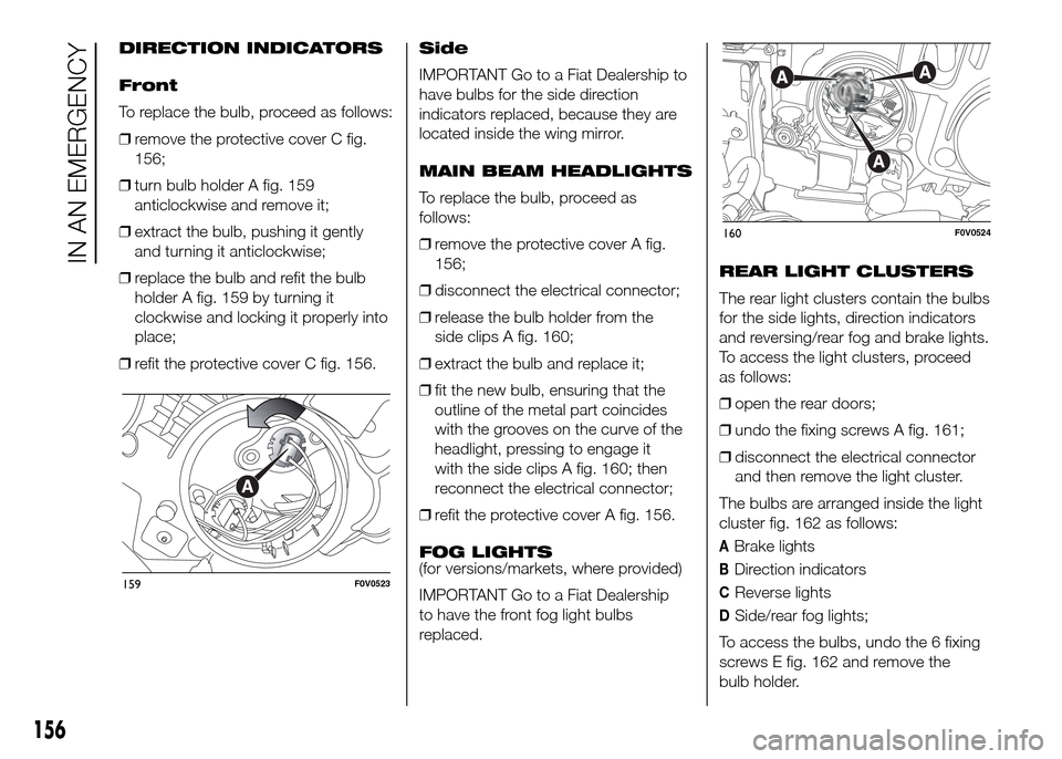
❒turn bulb holder A fig. 159
anticlockwise and remove it;
❒extract the bulb, pushing it gently
and turning it anticlockwise;
❒replace the bulb and refit the bulb
holder A fig. 159 by turning it
clockwise and locking it properly into
place;
❒refit the protective cover C fig. 156.Side
IMPORTANT Go to a Fiat Dealership to
have bulbs for the side direction
indicators replaced, because they are
located inside the wing mirror.
MAIN BEAM HEADLIGHTS
To replace the bulb, proceed as
follows:
❒remove the protective cover A fig.
156;
❒disconnect the electrical connector;
❒release the bulb holder from the
side clips A fig. 160;
❒extract the bulb and replace it;
❒fit the new bulb, ensuring that the
outline of the metal part coincides
with the grooves on the curve of the
headlight, pressing to engage it
with the side clips A fig. 160; then
reconnect the electrical connector;
❒refit the protective cover A fig. 156.
FOG LIGHTS
(for versions/markets, where provided)
IMPORTANT Go to a Fiat Dealership
to have the front fog light bulbs
replaced.REAR LIGHT CLUSTERS
The rear light clusters contain the bulbs
for the side lights, direction indicators
and reversing/rear fog and brake lights.
To access the light clusters, proceed
as follows:
❒open the rear doors;
❒undo the fixing screws A fig. 161;
❒disconnect the electrical connector
and then remove the light cluster.
The bulbs are arranged inside the light
cluster fig. 162 as follows:
ABrake lights
BDirection indicators
CReverse lights
DSide/rear fog lights;
To access the bulbs, undo the 6 fixing
screws E fig. 162 and remove the
bulb holder.
159F0V0523
160F0V0524
156
IN AN EMERGENCY
Page 161 of 323
To change the bulb, push it in gently
and turn it anticlockwise (“bayonet”
type), then remove and replace it.
THIRD BRAKE LIGHTS
To replace the bulb proceed as follows:
❒for versions with tailgate, undo the
two fixing screws A fig. 163 and
remove the unit;
❒for versions with wing doors, remove
the rubber caps B fig. 164 and
manoeuvre the holding tabs C, then
remove the unit;❒for versions with high roof and swing
doors, remove the pressure-fit plastic
guard A fig. 165 and rubber cap B
fig. 165, using a screwdriver, release
the retaining tags as shown in the
figure and remove the unit;
❒manoeuvre the appropriate tabs and
remove the bulb holder;
❒remove the snap-fitted bulb and
replace.
161F0V0034162F0V0525
163F0V0163
164F0V0164
165F0V0231
157
Page 162 of 323

NUMBER PLATE LIGHTS
(for hatchback
versions)
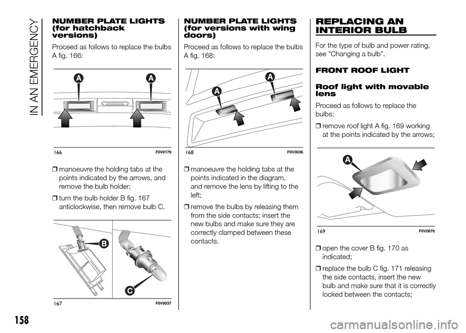
Proceed as follows to replace the bulbs
A fig. 166:
❒manoeuvre the holding tabs at the
points indicated by the arrows, and
remove the bulb holder;
❒turn the bulb holder B fig. 167
anticlockwise, then remove bulb C.NUMBER PLATE LIGHTS
(for versions with wing
doors)
Proceed as follows to replace the bulbs
A fig. 168:
❒manoeuvre the holding tabs at the
points indicated in the diagram,
and remove the lens by lifting to the
left;
❒remove the bulbs by releasing them
from the side contacts; insert the
new bulbs and make sure they are
correctly clamped between these
contacts.REPLACING AN
INTERIOR BULB
For the type of bulb and power rating,
see "Changing a bulb".
FRONT ROOF LIGHT
Roof light with movable
lens
Proceed as follows to replace the
bulbs:
❒remove roof light A fig. 169 working
at the points indicated by the arrows;
❒open the cover B fig. 170 as
indicated;
❒replace the bulb C fig. 171 releasing
the side contacts, insert the new
bulb and make sure that it is correctly
locked between the contacts;
166F0V0179
167F0V0037
168F0V0036
169F0V0070
158
IN AN EMERGENCY
Page 163 of 323
❒close the cover and secure the roof
light into its housing, making sure it
locks properly into place.
Roof light with spot
lights (where provided)
Proceed as follows to replace the
bulbs:
❒operate in the points indicated by the
arrows and remove light A fig. 172;
❒open protective flap B fig. 173;❒replace the bulbs C releasing them
from the side contacts making sure
that the new bulbs are correctly
secured between the contacts;
❒close flap B fig. 173 and fix roof light
A fig. 172 in its housing, making sure
that it locks into place.REAR ROOF LIGHT
To replace the bulb, proceed as follows:
❒remove roof light A fig. 174 working
at the points indicated by the arrows;
❒open the cover B fig. 175 as
indicated;
170F0V0071
171F0V0072
172F0V0073
173F0V0074
174F0V0075
175F0V0071
159
Page 167 of 323
Engine compartment fuse box
fig. 180 - fig. 181
DEVICE PROTECTED FUSE AMPERE
Remote control switch for opening swing door (Cargo version) F09 10
Single tone hornF10 10
Main beam headlights F14 15
Heated rear window F20 30
Fog lightsF30 15
Rear power socket F85 15
Passenger compartment power socket F86 15
163
Page 170 of 323

CHANGING A WHEEL
The vehicle is originally equipped with
the Fix&Go automatic quick tyre repair
kit (see instructions in the next section).
As an alternative, the vehicle may
have a normal-sized spare wheel.
Wheel changing and correct use of the
jack and spare wheel call for some
precautions, as listed below.
108) 109) 110) 111)
Note for one-way tyres
One-way tyres have a few arrows
on the side indicating the rotation
direction. If a wheel is changed (when
punctured, for example) the direction of
the arrows on the spare wheel tyre
may not coincide with the rotation
direction of the wheel to be replaced.
In these conditions, too, the tyre still
maintains its safety features.
Anyway, it is recommended to have the
wheel repaired and refitted as soon as
possible, as the best performance is
achieved when the rotation direction of
all tyres coincides with the one
indicated by the arrows.
Please note that:
❒the jack weight is 4 kg;
❒the jack requires no adjustment;❒the jack cannot be repaired and in
the event of a fault it must be
replaced by another original one;
❒no tool other than its cranking device
may be fitted on the jack.
To change a wheel, proceed as follows:
❒stop the vehicle in a position that is
not dangerous for oncoming traffic
where you can change the wheel
safely. The ground should be flat
if possible, and sufficiently firm;
❒stop the engine and pull the
handbrake;
❒engage first gear or reverse;
❒wear the reflective safety jacket
(compulsory by law in certain
countries) before getting out of the
vehicle;
❒indicate that the vehicle has broken
down using the devices required by
the law in the current country (e.g.
warning triangle, hazard lights, etc.);
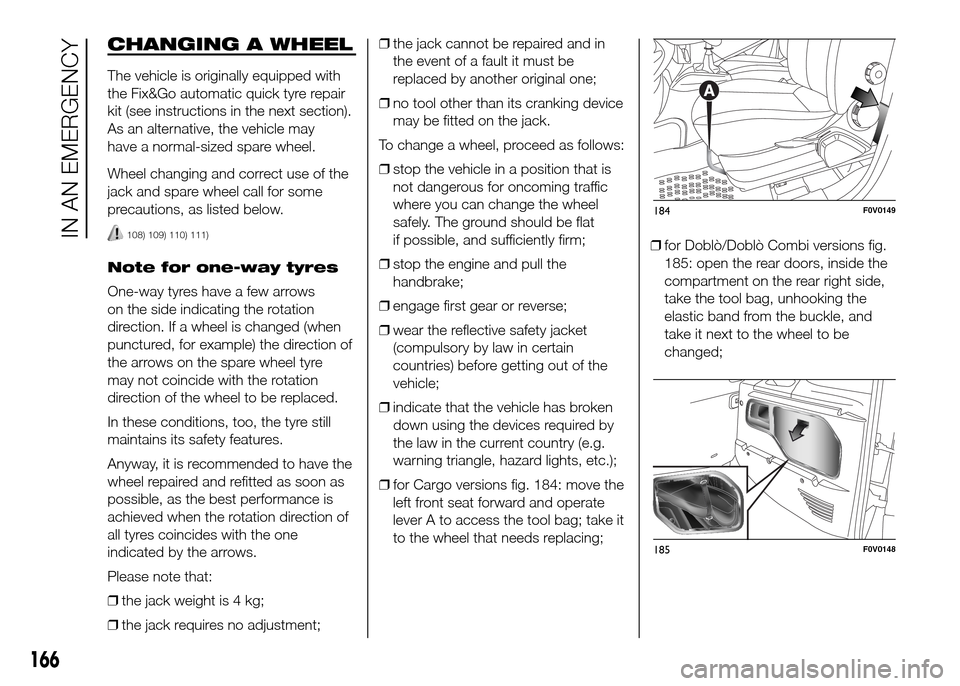
❒for Cargo versions fig. 184: move the
left front seat forward and operate
lever A to access the tool bag; take it
to the wheel that needs replacing;❒for Doblò/Doblò Combi versions fig.
185: open the rear doors, inside the
compartment on the rear right side,
take the tool bag, unhooking the
elastic band from the buckle, and
take it next to the wheel to be
changed;
184F0V0149
185F0V0148
166
IN AN EMERGENCY
Page 174 of 323

WARNING
108) The spare wheel (where
provided) is specifically for your
vehicle. Therefore, it must not be
used on other models. Do not
use spare wheels of other models
on your vehicle. The spare wheel
must be used only in an
emergency. Use of the spare
wheel must kept to the minimum
necessary.
109) Use your hazard lights, warning
triangle, etc. to show that your
vehicle is stationary according to
the regulations in force.
Passengers should get out of the
vehicle, particularly if it is heavily
loaded, and wait for the wheel
to be changed away from the
traffic. If you are on a slope or
uneven surface, place wedges or
other suitable objects under the
wheels to secure the vehicle.
Have the wheel repaired and
refitted as soon as possible. Do
not apply grease to the bolt
threads before assembly: they
might spontaneously unscrew.110) Use the jack only to replace
wheels on the vehicle with which
it is supplied or on other vehicles
of the same model. Never use
the jack for other purposes, such
as lifting other models. Never
use the jack to carry out repairs
under the vehicle. Incorrect
positioning of the jack may cause
the lifted vehicle to fall. Do not
use the jack for loads higher than
those shown on the label.
111) Incorrect hub cap assembly
may cause it to come off when the
vehicle is moving. Never tamper
with the inflation valve. Never
introduce tools of any kind
between rim and tyre. Check tyre
and spare wheel pressures
regularly, referring to the values
shown in the "Technical
specifications" section.
FIX&GO automatic
QUICK TYRE REPAIR
KIT
The quick repair kit Fix&Go automatic is
contained in a suitable bag inside the
compartment on the right rear side
or, for Cargo versions, under the
passenger seat (for versions with fixed
or movable seat), or in the glove
compartment (for versions with folding
seat).
The quick tyre repair kit contains fig.
200:
❒bottle A containing sealer and fitted
with: – filler tube B
– sticker C bearing the notice “max. 80
km/h”, to be placed in a position visible
to the driver (on the instrument panel)
after fixing the tyre
200F0V0093
170
IN AN EMERGENCY