Page 152 of 298

DIRECTION INDICATORS
Front
To replace the bulb, proceed as follows:
remove the protective cover C fig.
154;
turn bulb holder A fig. 157
anticlockwise and remove it;
extract the bulb, pushing it gently
and turning it anticlockwise;
replace the bulb and refit the bulb
holder A fig. 157 by turning it clockwise
and locking it properly into place;
refit the protective cover C fig. 154.
Side
IMPORTANT Go to a Fiat Dealership to
have bulbs for the side direction
indicators replaced, because they are
located inside the wing mirror.MAIN BEAM HEADLIGHTS
To replace the bulb, proceed as
follows:
remove the protective cover A fig.
154;
disconnect the electrical connector;
release the bulb holder from the
side clips A fig. 158;
extract the bulb and replace it;
fit the new bulb, ensuring that the
outline of the metal part coincides with
the grooves on the curve of the
headlight, pressing to engage it with the
side clips A fig. 158; then reconnect
the electrical connector;
refit the protective cover A fig. 154.FOG LIGHTS
(for versions/markets, where provided)
IMPORTANT Go to a Fiat Dealership
to have the front fog light bulbs
replaced.
REAR LIGHT CLUSTERS
The rear light clusters contain the bulbs
for the side lights, direction indicators
and reversing/rear fog and brake lights.
To access the light clusters, proceed
as follows:
open the rear doors;
undo the fixing screws A fig. 159;
disconnect the electrical connector
and then remove the light cluster.
The bulbs are arranged inside the light
cluster fig. 160 as follows:
ABrake lights
BDirection indicators
CReverse lights
DSide/rear fog lights;
To access the bulbs, undo the 6 fixing
screws E fig. 160 and remove the
bulb holder.
To change the bulb, push it in gently
and turn it anticlockwise (“bayonet”
type), then remove and replace it.
157F0V0523
158F0V0524
148
IN AN EMERGENCY
Page 154 of 298

NUMBER PLATE LIGHTS
(for hatchback
versions)
Proceed as follows to replace the bulbs
A fig. 164:
manoeuvre the holding tabs at the
points indicated by the arrows, and
remove the bulb holder;
turn the bulb holder B fig. 165
anticlockwise, then remove bulb C.NUMBER PLATE LIGHTS
(for versions with wing
doors)
Proceed as follows to replace the bulbs
A fig. 166:
manoeuvre the holding tabs at the
points indicated in the diagram, and
remove the lens by lifting to the left;
remove the bulbs by releasing them
from the side contacts; insert the new
bulbs and make sure they are correctly
clamped between these contacts.
REPLACING AN
INTERIOR BULB
For the type of bulb and power rating,
see "Changing a bulb".
FRONT ROOF LIGHT
Roof light with movable lens
Proceed as follows to replace the
bulbs:
remove roof light A fig. 167 working
at the points indicated by the arrows;
open the cover B fig. 168 as
indicated;
replace the bulb C fig. 169 releasing
the side contacts, insert the new bulb
and make sure that it is correctly locked
between the contacts;
close the cover and secure the roof
light into its housing, making sure it
locks properly into place.
164F0V0179
165F0V0037
166F0V0036
167F0V0070
150
IN AN EMERGENCY
Page 155 of 298
Roof light with spot lights (where
provided)
Proceed as follows to replace the
bulbs:
operate in the points indicated by
the arrows and remove light A fig. 170;
open protective flap B fig. 171;
replace the bulbs C releasing them
from the side contacts making sure that
the new bulbs are correctly secured
between the contacts;
close flap B fig. 171 and fix roof light
A fig. 170 in its housing, making sure
that it locks into place.REAR ROOF LIGHT
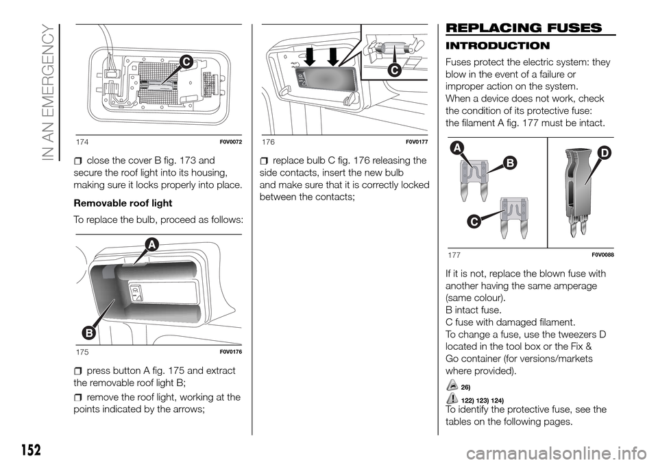
To replace the bulb, proceed as follows:
remove roof light A fig. 172 working
at the points indicated by the arrows;
open the cover B fig. 173 as
indicated;
replace the bulb C fig. 174 releasing
the side contacts, insert the new bulb
and make sure that it is correctly locked
between the contacts;
168F0V0071
169F0V0072
170F0V0073
171F0V0074
172F0V0075
173F0V0071
151
Page 156 of 298

close the cover B fig. 173 and
secure the roof light into its housing,
making sure it locks properly into place.
Removable roof light
To replace the bulb, proceed as follows:
press button A fig. 175 and extract
the removable roof light B;
remove the roof light, working at the
points indicated by the arrows;
replace bulb C fig. 176 releasing the
side contacts, insert the new bulb
and make sure that it is correctly locked
between the contacts;
REPLACING FUSES
INTRODUCTION
Fuses protect the electric system: they
blow in the event of a failure or
improper action on the system.
When a device does not work, check
the condition of its protective fuse:
the filament A fig. 177 must be intact.
If it is not, replace the blown fuse with
another having the same amperage
(same colour).
B intact fuse.
C fuse with damaged filament.
To change a fuse, use the tweezers D
located in the tool box or the Fix &
Go container (for versions/markets
where provided).
26)
122) 123) 124)To identify the protective fuse, see the
tables on the following pages.
174F0V0072
175F0V0176
176F0V0177
177F0V0088
152
IN AN EMERGENCY
Page 160 of 298
Passenger compartment fuse boxes
fig. 180 - fig. 181
DEVICE PROTECTEDFUSE AMPERE
Door locking/unlocking motors, dead lock actuator motors, tailgate unlocking motor F38 20
Supply + battery for EOBD diagnosis socket, radio, tyre pressure monitoring control unit F36 10
Windscreen/rear window washer pump F43 15
Electric window motor on passenger-side front door F48 20
Left low beam, headlight corrector F13 7,5
Electric window motor on driver-side front door F47 20
156
IN AN EMERGENCY
Page 168 of 298

if the required pressure is reached,
restart driving. Do not exceed 80 km/h.
Avoid sudden acceleration or braking.
After driving for about 8 km / 5 miles,
place the vehicle in a safe and suitable
area, engaging the parking brake.
Take the kit, make sure that the on-off
switch E is in the0position and insert
the electrical connector in the vehicle’s
12V socket. Remove the cap from
the valve of repaired tyre, disconnect
and pull out the black inflation tube fig.
203, connect it to the valve and lock
it with the lever. Inspect the pressure
gauge F to check the tyre pressure fig.
201;
if the pressure is lower than 1.8 bar /
26 psi, the TYRE IS TOO DAMAGED
AND CANNOT BE REPAIRED. Remove
and place the kit in the specific
compartment and contact a Fiat
Dealership;
if the pressure is equal to or higher
than 1.8 bar / 26 psi, switch on the
compressor and reach the required
pressure. Disconnect and replace the
kit in the specific compartment.
Carefully drive and reach the Fiat
Dealership as soon as possible;PRESSURE RESTORING
The compressor can also be used to
check and, if necessary, restore the tyre
pressure.
Disconnect and pull out the black
inflation tube, connect and block it with
the stalk to the tyre valve fig. 203.
With the same procedure it is possible
to inflate bicycle tyres and balloons.CARTRIDGE
REPLACEMENT
Only use Fix&Go original cartridges
which can be purchased at Fiat
Dealership.
To remove the cartridge B, disconnect
the black inflation tube coupling A,
turn the cartridge B anticlockwise and
then lift it. Insert the new cartridge, turn
it clockwise to the end of its travel,
insert the black inflation tube coupling
A, blocking it with the lever and then
rewind the transparent tube into its
compartment on the compressor fig.
204.
203F0V0099
204F0V0100
164
IN AN EMERGENCY
Page 170 of 298

IMPORTANT Remember that the brake
booster and the electric power steering
system are not active until the engine
is started, so you will need to apply
much more force to the brake pedal or
steering wheel.
WARNING
29)Never use a fast battery-charger for
emergency starting of the engine as this
could damage the electronic systems
of your vehicle, particularly the ignition and
fuel supply control units.
WARNING
131)This procedure must be performed by
qualified personnel as incorrect actions
may cause high-intensity electrical
discharge. Furthermore, battery fluid is
poisonous and corrosive: avoid contact
with skin and eyes. Keep naked flames
away from the battery. No smoking. Do not
cause sparks.
FUEL CUT-OFF
SYSTEM
This intervenes in the case of an impact
causing:
the fuel supply cut-off with the
engine consequently switching off;
the automatic unlocking of the
doors;
the switching on of the interior lights;
switching on of the hazard warning
lights (to deactivate the lights press
the dedicated button on the
dashboard).
132)When the system has been triggered,
the message “Fuel cut off, see
handbook” is displayed on some
versions.
Check carefully for fuel leaks, for
instance in the engine compartment,
under the vehicle or near the tank area.
After a collision, turn the ignition key
to STOP to prevent the battery from
running down.
The following procedure should be
carried out to restore the correct
operation of the vehicle:
turn the ignition key to the MAR
position;
activate the right direction indicator;
deactivate the right direction
indicator;
activate the left direction indicator;
deactivate the left direction indicator;
activate the right direction indicator;
deactivate the right direction
indicator;
activate the left direction indicator;
deactivate the left direction indicator;
turn the ignition key to the OFF
position.
WARNING
132)If, after an impact, you smell fuel or
notice leaks from the fuel supply system,
do not reactivate the system to avoid
the risk of fire.
166
IN AN EMERGENCY
Page 171 of 298

LIFTING THE
VEHICLE
If the vehicle needs to be lifted, go to a
Fiat Dealership which is equipped
with the arm hoist or workshop lift.
TOWING THE
VEHICLE
The tow ring provided with the vehicle
is located in the tool box behind the left
seat backrest (Cargo versions) or in
the boot (Doblò / Doblò Combi
versions).
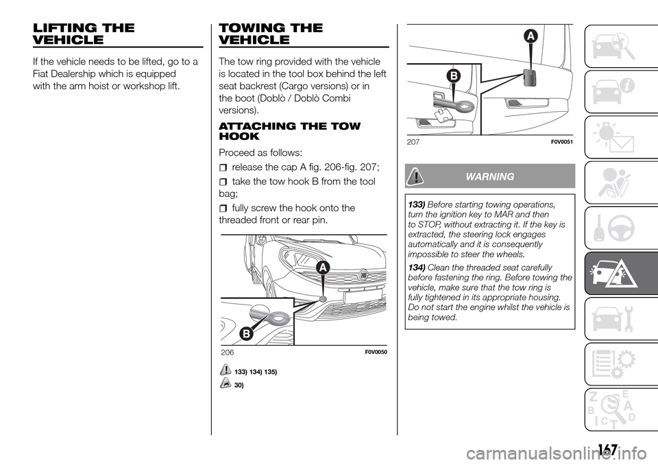
ATTACHING THE TOW
HOOK
Proceed as follows:
release the cap A fig. 206-fig. 207;
take the tow hook B from the tool
bag;
fully screw the hook onto the
threaded front or rear pin.
133) 134) 135)
30)
WARNING
133)Before starting towing operations,
turn the ignition key to MAR and then
to STOP, without extracting it. If the key is
extracted, the steering lock engages
automatically and it is consequently
impossible to steer the wheels.
134)Clean the threaded seat carefully
before fastening the ring. Before towing the
vehicle, make sure that the tow ring is
fully tightened in its appropriate housing.
Do not start the engine whilst the vehicle is
being towed.
206F0V0050
207F0V0051
167