2016 FIAT 500E lock
[x] Cancel search: lockPage 52 of 132

POWER SUNROOF
The power sunroof roof switch is located in the overhead console.
WARNING!
•Never leave children alone in a vehicle, or with access to an unlocked vehicle.
Never leave the Key Fob in or near the vehicle, or in a location accessible to chil-
dren.Occupants, particularly unattended children, can become entrapped by the
power sunroof while operating the power sunroof switch.Such entrapment may
result in serious injury or death.
•In a collision, there is a greater risk of being thrown from a vehicle with an open
sunroof.You could also be seriously injured or killed.Always fasten your seat belt
properly and make sure all passengers are properly secured.
•
Do not allow small children to operate the sunroof.Never allow your fingers, other
body parts, or any object to project through the sunroof opening.Injury may result.
To Open
Push and hold the power sunroof switch rearward for approximately one second and the
sunroof will stop at the vented position.Push the switch a second time and hold for ap-
proximately one second and release, the sunroof will open fully, then stop automatically.
This is called “Express Open”.During Express Open operation, any movement of the sun-
roof switch will stop the sunroof.
Power Sunroof Switch
OPERATING YOUR VEHICLE
50
Page 58 of 132

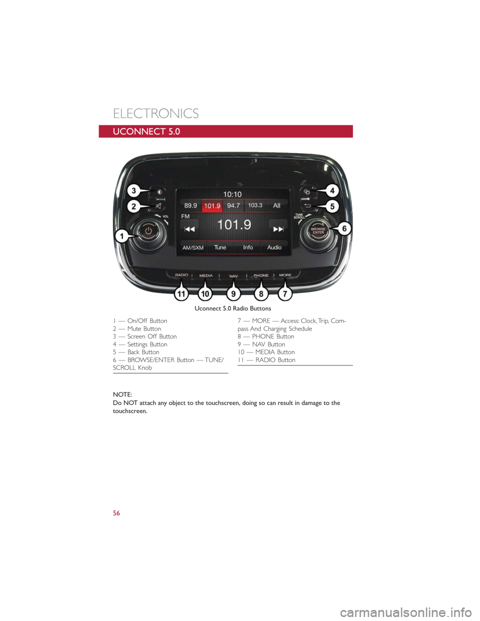
UCONNECT 5.0
NOTE:
Do NOT attach any object to the touchscreen, doing so can result in damage to the
touchscreen.
Uconnect 5.0 Radio Buttons
1 — On/Off Button
2 — Mute Button
3 — Screen Off Button
4 — Settings Button
5 — Back Button
6 — BROWSE/ENTER Button — TUNE/
SCROLL Knob7 — MORE — Access: Clock, Trip, Com-
pass And Charging Schedule
8 — PHONE Button
9 — NAV Button
10 — MEDIA Button
11 — RADIO Button
ELECTRONICS
56
Page 59 of 132

Clock Setting
To start the clock setting procedure:
1.Push the Settings button on the faceplate and then press the “Clock and Date” button
on the touchscreen.
2.Press the “Set Time” button on the touchscreen.
3.Press the “Up” or “Down” arrows to adjust the hours or minutes, then select the
“AM” or “PM” button on the touchscreen.You can also select 12hr or 24hr format by
pressing the desired button on the touchscreen.
4.Once the time is set press the “Done” button on the touchscreen to exit the time
screen.
NOTE:
In the Clock Setting Menu you can also select Display Clock.Display Clock turns the
clock display in the status bar on or off.
Equalizer, Balance And Fade
1.Push the Settings button on the faceplate.
2.Scroll down and press the “Audio” button on the touchscreen to open the Audio
menu.
3.The Audio Menu shows the following options for you to customize your audio set-
tings.
Equalizer
Press the “Equalizer” button on the touchscreen to adjust the Bass, Mid and Treble.Use
the “+” or “-” button on the touchscreen to adjust the equalizer to your desired settings.
Balance/Fade
Press the “Balance/Fade” button on the touchscreen to adjust the sound from the speak-
ers.Use the arrow buttons on the touchscreen to adjust the sound level from the front
and rear or right and left side speakers.Press the Center “C” button on the touchscreen
to reset the balance and fade to the factory setting.
Speed Adjusted Volume
Press the “Speed Adjusted Volume” button on the touchscreen to select between OFF, 1,
2or3.This will decrease the radio volume relative to a decrease in vehicle speed.
Surround Sound
Press the “Surround Sound” button on the touchscreen, select On or Off followed by
pressing the back arrow button on the touchscreen.When this feature is activated, it pro-
vides simulated surround sound mode.
ELECTRONICS
57
Page 81 of 132

Uconnect Customer Programmable Features
The Uconnect system allows you to access Customer Programmable feature settings.
To change a setting:
1.Push the SETTINGS
button located on the right side of the display.
2.Select a programmable feature you would like to adjust.
3.Make your selection highlighting the button.
Depending on the vehicles options, the following feature settings are available:
•Display•Audio
•Clock & Date•Phone/Bluetooth
•Safety/Assistance•SiriusXM Setup
•Lights•Voice
•Doors & Locks•Restore Settings
•Engine Off Options•Units
•Clear Personal Data•Charging Schedule
TRIP BUTTON
The Trip button is located on the end of
the wiper lever to the right of the steering
column.The trip button can be used to
display and reset the following functions:
•Motor Power (Kilowatts)
•Trip A
•Trip B
•Tire Pressure
•Short push (less than 1 second) to dis-
play different functions.
•Long push (more than 1 second) to re-
set and start a new trip.
Trip Button
ELECTRONICS
79
Page 85 of 132

ROADSIDE ASSISTANCE
•If your FIAT 500e requires jump start assistance, tire service, lockout service or towing
due to a defect covered under the Basic Limited Warranty, dial toll-free
1-888-242-6342.See your Warranty booklet for further details.
•Provide your name, vehicle identification number and license plate number.
•Provide your location, including telephone number, from which you are calling.
•Briefly describe the nature of the problem and answer a few simple questions.
•You will be given the name of the service provider and an estimated time of arrival.If
you feel you are in an “unsafe situation”, please let us know.With your consent, we will
contact local police or safety authorities.
WARNING AND INDICATOR LIGHTS
IMPORTANT:The warning / indicator lights switch on in the instrument panel together
with a dedicated message and/or acoustic signal when applicable.These indications are
indicative and precautionary and as such must not be considered as exhaustive and/or
alternative to the information contained in the Owner’s Manual, which you are advised to
read carefully in all cases.Always refer to the information in this chapter in the event of a
failure indication.
All active telltales will display first if applicable.The system check menu may appear differ-
ent based upon equipment options and current vehicle status.
This guide illustrates and describes the operation of warning and indicator telltales that
are either standard or optional based on the vehicle build.FCA reserves the right to
make changes in design and specifications and/or make additions to or improvements to
its products without imposing any obligation upon itself to install them on products previ-
ously manufactured.
Instrument Cluster Warning Lights
– Electric Vehicle System Warning Light
This indicator will illuminate when there is a malfunction in the Electric Vehicle System.If
the EVS malfunction light comes on while driving or charging see your authorized dealer
as soon as possible.
– Regenerative Brake System Warning Light
If the light turns on and remains on while driving, it suggests that there is a potential
problem with the Regenerative Brake System (RBS) and the need for system service.See
your authorized dealer as soon as possible.
WHAT TO DO IN EMERGENCIES
83
Page 86 of 132

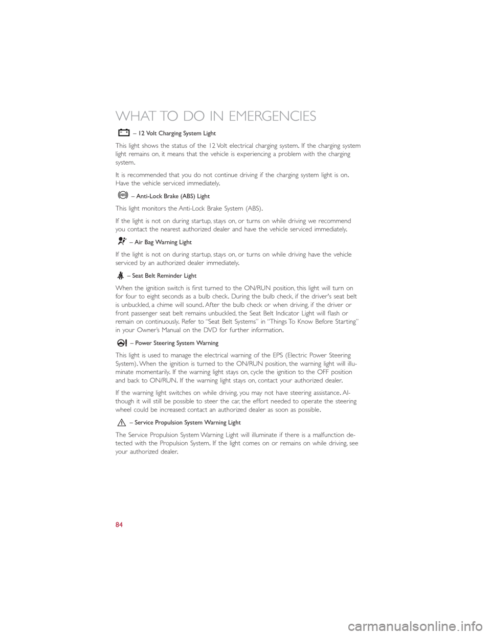
– 12 Volt Charging System Light
This light shows the status of the 12 Volt electrical charging system.If the charging system
light remains on, it means that the vehicle is experiencing a problem with the charging
system.
It is recommended that you do not continue driving if the charging system light is on.
Have the vehicle serviced immediately.
– Anti-Lock Brake (ABS) Light
This light monitors the Anti-Lock Brake System (ABS).
If the light is not on during startup, stays on, or turns on while driving we recommend
you contact the nearest authorized dealer and have the vehicle serviced immediately.
– Air Bag Warning Light
If the light is not on during startup, stays on, or turns on while driving have the vehicle
serviced by an authorized dealer immediately.
– Seat Belt Reminder Light
When the ignition switch is first turned to the ON/RUN position, this light will turn on
for four to eight seconds as a bulb check.During the bulb check, if the driver's seat belt
is unbuckled, a chime will sound.After the bulb check or when driving, if the driver or
front passenger seat belt remains unbuckled, the Seat Belt Indicator Light will flash or
remain on continuously.Refer to “Seat Belt Systems” in “Things To Know Before Starting”
in your Owner’s Manual on the DVD for further information.
– Power Steering System Warning
This light is used to manage the electrical warning of the EPS (Electric Power Steering
System).When the ignition is turned to the ON/RUN position, the warning light will illu-
minate momentarily.If the warning light stays on, cycle the ignition to the OFF position
and back to ON/RUN.If the warning light stays on, contact your authorized dealer.
If the warning light switches on while driving, you may not have steering assistance.Al-
though it will still be possible to steer the car, the effort needed to operate the steering
wheel could be increased: contact an authorized dealer as soon as possible.
– Service Propulsion System Warning Light
The Service Propulsion System Warning Light will illuminate if there is a malfunction de-
tected with the Propulsion System.If the light comes on or remains on while driving, see
your authorized dealer.
WHAT TO DO IN EMERGENCIES
84
Page 87 of 132

– Brake Warning Light
This light monitors various brake functions, including brake fluid level and parking brake
application.If the brake light turns on, it may indicate that the parking brake is applied,
that the brake fluid level is low, or that there is a problem with the brake system master
cylinder reservoir.
If the light remains on when the parking brake has been disengaged, and the fluid level is
at the full mark on the master cylinder reservoir, it indicates a possible brake hydraulic
system malfunction or that a problem with the Brake Booster has been detected by the
Anti-Lock Brake System (ABS)/Electronic Stability Control (ESC) system.In this case, the
light will remain on until the condition has been corrected.If the problem is related to
the brake booster, the ABS pump will run when applying the brake, and a brake pedal
pulsation may be felt during each stop.
The dual brake system provides a reserve braking capacity in the event of a failure to a
portion of the hydraulic system.A leak in either half of the dual brake system is indicated
by the Brake Warning Light, which will turn on when the brake fluid level in the master
cylinder has dropped below a specified level.The light will remain on until the cause is
corrected.
Vehicles equipped with the Anti-Lock Brake System (ABS) are also equipped with Elec-
tronic Brake Force Distribution (EBD).In the event of an EBD failure, the Brake Warning
Light will turn on along with the ABS Light.Immediate repair to the ABS system is re-
quired.
Operation of the Brake Warning Light can be checked by turning the ignition switch from
the OFF position to the ON/RUN position.The light should illuminate for approximately
two seconds.The light should then turn off unless the parking brake is applied or a brake
fault is detected.If the light does not illuminate, have the light inspected by an authorized
dealer.
The light also will turn on when the parking brake is applied with the ignition switch in
the ON/RUN position.
NOTE:
This light shows only that the parking brake is applied.It does not show the degree of
brake application.
WARNING!
Driving a vehicle with the red brake light on is dangerous.Part of the brake system
may have failed.It will take longer to stop the vehicle.You could have a collision.Have
the vehicle checked immediately.
WHAT TO DO IN EMERGENCIES
85
Page 97 of 132

If the tire pressure is 19 psi (1.3 Bar) or higher:
1.Push the Power Button (4) to turn on Tire Service Kit and inflate the tire to the pres-
sure indicated on the tire and loading information label on the driver-side door open-
ing.
NOTE:
If the tire becomes over-inflated, push the Deflation Button to reduce the tire pressure
to the recommended inflation pressure before continuing.
2.Disconnect the Tire Service Kit from the valve stem, reinstall the cap on the valve
stem and unplug from 12 Volt outlet.
3.Place the Tire Service Kit in its proper storage area in the vehicle.
4.Have the tire inspected and repaired or replaced at the earliest opportunity at an
authorized dealer or tire service center.
5.Remove the Speed Limit sticker from the instrument panel after the tire has been
repaired.
6.Replace the Sealant Bottle (1) and Sealant Hose (6) assembly at your authorized
dealer as soon as possible.Refer to (F) “Sealant Bottle and Hose Replacement”.
NOTE:
When having the tire serviced, advise the authorized dealer or service center that the
tire has been sealed using the Tire Service Kit.
(F) Sealant Bottle And Hose Replacement:
1.Uncoil the Sealant Hose (6) (clear in color).
2.Locate the round Sealant Bottle release button in the recessed area under the sealant
bottle.
3.Push the Sealant Bottle release button.The Sealant Bottle (1) will pop up.Remove the
bottle and dispose of it accordingly.
4.Clean any remaining sealant from the Tire Service Kit housing.
5.Position the new Sealant Bottle (1) in the housing so that the Sealant Hose (6) aligns
with the hose slot in the front of the housing.Push the bottle into the housing.An
audible click will be heard indicating the bottle is locked into place.
6.Verify that the cap is installed on the fitting at the end of the Sealant Hose (6) and
return the hose to its storage area (located on the bottom of the air pump).
7.Return the Tire Service Kit to its storage location in the vehicle.
WHAT TO DO IN EMERGENCIES
95