Page 125 of 432
Emergency Operation
In case of electrical failure, the sunroof can be operated
with the hex wrench that is located in the glove compart-
ment. There is a plug located in the rear of the sunroof
opening at the center of the vehicle. Removing the plug
reveals a hex opening in the motor assembly of the
sunroof. Insert the hex wrench and turn, moving the
sunroof to the desired location.
Sun Shade — If Equipped
For vehicles equipped with either a power sunroof or a
fixed glass roof, there is a sun shade that can be open or
closed. To open the sun shade, push the tab and move the
shade to a full open position.
ELECTRICAL POWER OUTLETS
There is a standard 12 Volt (13 Amp) power outlet,
located in the floor console, for added convenience. This
power outlet can power mobile phones, electronics and
other low power devices.
Manual Sun Shade
3
UNDERSTANDING THE FEATURES OF YOUR VEHICLE 123
Page 388 of 432
CavityMaxi Fuse Mini Fuse Description
F16 –7.5 Amp Brown Transmission
F17 – 25 Amp Clear Powertrain (Multiair – If Equipped)
F17 – 15 Amp Blue Powertrain
F18 – 15 Amp Blue Powertrain
F18 – 5 Amp Tan Powertrain (Multiair – If Equipped)
F19 –7.5 Amp Brown Air Conditioning
F20 – 15 Amp Blue Heated Seats – If Equipped
F21 – 15 Amp Blue Fuel Pump
F22 –20 Amp Yellow Powertrain
F23 –20 Amp Yellow Anti-Lock Brake Valves
F24 –7.5 Amp Brown Stability Control System
F30 – 15 Amp Blue Fog Lamps
F82 30 Amp Green –Sunroof/Convertible Top
F83 20 Amp Yellow –Cooling Pump – If Equipped
F84 – 10 Amp Red Transmission
386 MAINTAINING YOUR VEHICLE
Page 402 of 432
Maintenance Chart
Mileage or time passed (whichever comes first)20,000
30,000
40,000
50,000
60,000
70,000
80,000
90,000
100,000
110,000
120,000
130,000
140,000
150,000
Or Years: 2 3 4 5 6 7 8 9 10 11 12 13 14 15
Or Kilometers:
32,000
48,000
64,000
80,000
96,000
112,000
128,000
144,000
160,000
176,000
192,000
208,000
224,000
240,000
Additional Inspections
Inspect the CV joints. XX X XX
Inspect front suspension, tie rod ends, boot seals,
and replace if necessary. XXX X X X X
Inspect brake linings, replace if needed. X X X X X X X
Inspect parking brake function, adjust as neces-
sary. XXX X X X X
Additional Maintenance
Replace cabin/air conditioning filter. X X X X X X X
Clean and lube sun roof tracks. X X X X X X X X X X X X X X
400 MAINTENANCE SCHEDULES
Page 425 of 432

Change Interval....................... .349
Checking ............................ .348
Disposal ............................. .350
Filter ............................... .350
Filter Disposal ........................ .350
Pressure Warning Light ...................157
Recommendation ....................349, 393
Viscosity ............................ .350
Oil Filter, Change ........................ .350
Oil Filter, Selection ....................... .350
Oil Pressure Light ........................ .157
Onboard Diagnostic System ..................344
Operating Precautions ..................... .344
Operator Manual (Owner’s Manual) .............5
Overheating, Engine ...................... .309
Owner’s Manual (Operator Manual) ..........5,408
Paint Care ............................. .373
Parking Brake ........................... .249Pets
....................................74
Placard, Tire And Loading Information ..........270
Power Door Locks ............................23
Mirrors ...............................89
Outlet (Auxiliary Electrical Outlet) ...........123
Steering ............................. .248
Sunroof ............................. .121
Windows ..............................24
Pregnant Women And Seat Belts ...............36
Preparation For Jacking .....................324
Pretensioners Seat Belts ..............................37
Radial Ply Tires ......................... .278
Radio Frequency General Information ...................15, 21
Radio Operation ......................... .213
Rear Liftgate (Sedan) .......................25
10
INDEX 423
Page 428 of 432

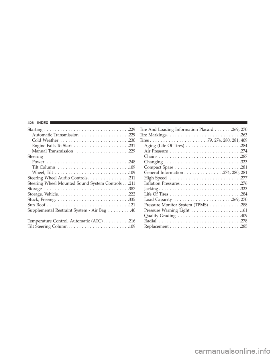
Starting............................... .229
Automatic Transmission ..................229
Cold Weather ......................... .230
Engine Fails To Start .....................231
Manual Transmission ....................229
Steering Power .............................. .248
Tilt Column .......................... .109
Wheel, Tilt ........................... .109
Steering Wheel Audio Controls ................211
Steering Wheel Mounted Sound System Controls . . .211
Storage ............................... .387
Storage, Vehicle .......................... .222
Stuck, Freeing ........................... .335
Sun Roof .............................. .121
Supplemental Restraint System - Air Bag .........40
Temperature Control, Automatic (ATC) ..........216
Tilt Steering Column ...................... .109Tire And Loading Information Placard
.......269, 270
Tire Markings ........................... .263
Tires..................... .79, 274, 280, 281, 409
Aging (Life Of Tires) .....................284
Air Pressure .......................... .274
Chains .............................. .287
Changing ............................ .323
Compact Spare ........................ .281
General Information ...............274, 280, 281
High Speed .......................... .277
Inflation Pressures ...................... .276
Jacking .............................. .323
Life Of Tires .......................... .284
Load Capacity ..................... .269, 270
Pressure Monitor System (TPMS) ............288
Pressure Warning Light ...................161
Quality Grading ....................... .409
Radial .............................. .278
Replacement .......................... .285
426 INDEX
Page 431 of 432

INSTALLATION OF RADIO TRANSMITTING
EQUIPMENTSpecial design considerations are incorporated into this
vehicle’s electronic system to provide immunity to radio
frequency signals. Mobile two-way radios and telephone
equipment must be installed properly by trained person-
nel. The following must be observed during installation.
The positive power connection should be made directly
to the battery and fused as close to the battery as possible.
The negative power connection should be made to body
sheet metal adjacent to the negative battery connection.
This connection should not be fused.
Antennas for two-way radios should be mounted on the
roof or the rear area of the vehicle. Care should be used
in mounting antennas with magnet bases. Magnets may
affect the accuracy or operation of the compass on
vehicles so equipped.The antenna cable should be as short as practical and
routed away from the vehicle wiring when possible. Use
only fully shielded coaxial cable.
Carefully match the antenna and cable to the radio to
ensure a low Standing Wave Ratio (SWR).
Mobile radio equipment with output power greater than
normal may require special precautions.
All installations should be checked for possible interfer-
ence between the communications equipment and the
vehicle’s electronic systems.