Page 279 of 671

2. Push and hold the desired HomeLink button until theindicator light begins to flash after 20 seconds. Do not
release the button.
3. Without releasing the button proceed with
“Canadian/Gate Operator Programming” step 2 and
follow all remaining steps.
Using HomeLink
To operate, push and release the programmed HomeLink
button. Activation will now occur for the programmed
device (i.e. garage door opener, gate operator, security
system, entry door lock, home/office lighting, etc.) The
hand-held transmitter of the device may also be used at
any time.
Security
It is advised to erase all channels before you sell or turn
in your vehicle. To do this, push and hold the two outside buttons for 20
seconds until the red indicator flashes. Note that all
channels will be erased. Individual channels cannot be
erased.
The HomeLink Universal Transceiver is disabled when
the Vehicle Security Alarm is active.
Troubleshooting Tips
If you are having trouble programming HomeLink, here
are some of the most common solutions:
•
Replace the battery in the Garage Door Opener hand-
held transmitter.
• Push the LEARN button on the Garage Door Opener
to complete the training for a Rolling Code.
• Did you unplug the device for programming and
remember to plug it back in?
3
UNDERSTANDING THE FEATURES OF YOUR VEHICLE 277
Page 287 of 671

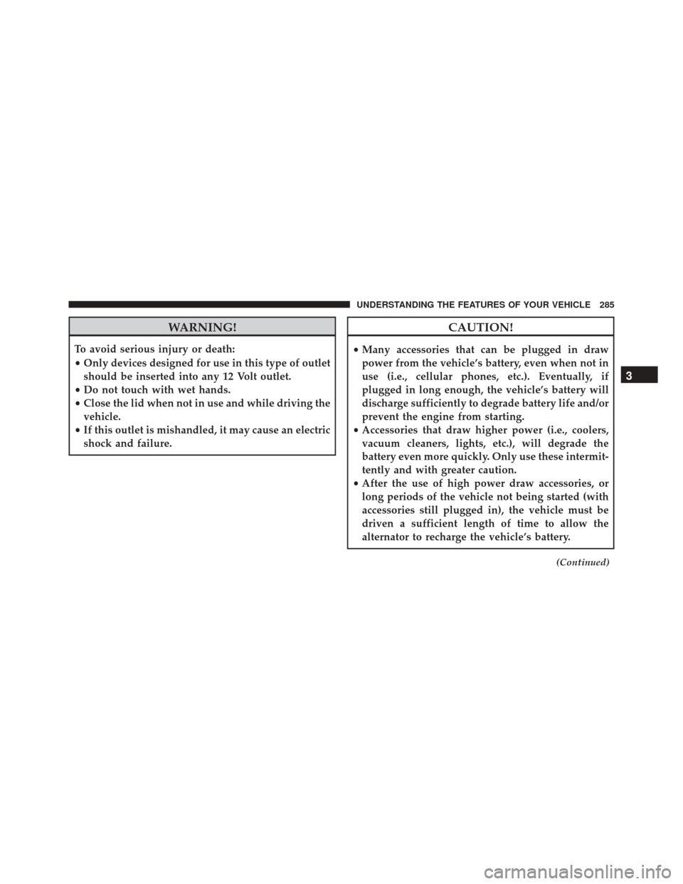
WARNING!
To avoid serious injury or death:
•Only devices designed for use in this type of outlet
should be inserted into any 12 Volt outlet.
• Do not touch with wet hands.
• Close the lid when not in use and while driving the
vehicle.
• If this outlet is mishandled, it may cause an electric
shock and failure.
CAUTION!
• Many accessories that can be plugged in draw
power from the vehicle’s battery, even when not in
use (i.e., cellular phones, etc.). Eventually, if
plugged in long enough, the vehicle’s battery will
discharge sufficiently to degrade battery life and/or
prevent the engine from starting.
• Accessories that draw higher power (i.e., coolers,
vacuum cleaners, lights, etc.), will degrade the
battery even more quickly. Only use these intermit-
tently and with greater caution.
• After the use of high power draw accessories, or
long periods of the vehicle not being started (with
accessories still plugged in), the vehicle must be
driven a sufficient length of time to allow the
alternator to recharge the vehicle’s battery.
(Continued)
3
UNDERSTANDING THE FEATURES OF YOUR VEHICLE 285
Page 333 of 671
•UP Arrow Button
Push and release the UP arrow button to scroll
upward through the main menus (Odometer,
Digital Vehicle Speed, Trip Info, Range To Empty,
Average Fuel Economy, Current Fuel Economy, Stored
Messages, Settings).
• RIGHT Arrow Button
Push and release the RIGHT arrow button to
access the submenu screens of a main menu
item. Push and hold the RIGHT arrow button
for two seconds to reset displayed/selected
features that can be reset.
Electronic Vehicle Information Center (EVIC)
Messages
• Key Fob Battery Low
• Wrong Key Fob
EVIC Steering Wheel Buttons (Two–Button EVIC
Controls)
4
UNDERSTANDING YOUR INSTRUMENT PANEL 331
Page 334 of 671
•Key Fob Damaged
• Key In Ignition
• Left Turn Signal Out
• Right Turn Signal Out
• Turn Signal On
• Lights On
• Low Beam Headlight Out
• High Beam Headlight Out
• License Plate Light Out
• Backup Light Out
• Brake Light Out
• Parking Light Out
• Service Air Bag System •
Service Air Bag Warning Light
• Washer Fluid Low
• Parking Brake Engaged
• Brake Fluid Low
• Service Electronic Braking System
• Engine Temperature Hot
• Battery Voltage Low
• Oil Pressure Low
• Fuel Low
• Service Antilock Brake System
• Service Electronic Throttle Control
• Transmission Too Hot
• Service Power Steering
332 UNDERSTANDING YOUR INSTRUMENT PANEL
Page 389 of 671

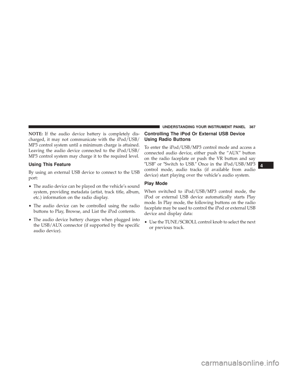
NOTE:If the audio device battery is completely dis-
charged, it may not communicate with the iPod/USB/
MP3 control system until a minimum charge is attained.
Leaving the audio device connected to the iPod/USB/
MP3 control system may charge it to the required level.
Using This Feature
By using an external USB device to connect to the USB
port:
• The audio device can be played on the vehicle’s sound
system, providing metadata (artist, track title, album,
etc.) information on the radio display.
• The audio device can be controlled using the radio
buttons to Play, Browse, and List the iPod contents.
• The audio device battery charges when plugged into
the USB/AUX connector (if supported by the specific
audio device).
Controlling The iPod Or External USB Device
Using Radio Buttons
To enter the iPod/USB/MP3 control mode and access a
connected audio device, either push the “AUX” button
on the radio faceplate or push the VR button and say
�USB� or�Switch to USB.� Once in the iPod/USB/MP3
control mode, audio tracks (if available from audio
device) start playing over the vehicle’s audio system.
Play Mode
When switched to iPod/USB/MP3 control mode, the
iPod or external USB device automatically starts Play
mode. In Play mode, the following buttons on the radio
faceplate may be used to control the iPod or external USB
device and display data:
• Use the TUNE/SCROLL control knob to select the next
or previous track.
4
UNDERSTANDING YOUR INSTRUMENT PANEL 387
Page 400 of 671

•Mix
Air is directed through the floor, defrost, and
side window demist outlets. This setting
works best in cold or snowy conditions that
require extra heat to the windshield. This setting is
good for maintaining comfort while reducing mois-
ture on the windshield.
• Front Defrost
Air is directed through the windshield and side
window demist outlets. Use this mode with maxi-
mum blower and temperature settings for best wind-
shield and side window defrosting.
NOTE: The air conditioning compressor operates in Mix,
Defrost, or a blend of these modes, even if the Air
Conditioning (A/C) button is not pushed. This dehu-
midifies the air to help dry the windshield. To improve
fuel economy, use these modes only when necessary. 6. Electronic Rear Window Defrost
Push this button to turn on the rear window defroster
and the heated outside mirrors (if equipped). An indica-
tor in the button will illuminate when the rear window
defroster is on. The rear window defroster automatically
turns off after approximately 15 minutes. For an addi-
tional 15 minutes of operation, push the button a second
time.
NOTE:
•You can turn off the heated mirror feature at anytime
by pushing the rear window defroster switch a
second time.
• To prevent excessive battery drain, use the rear
window defroster only when the engine is operating.
398 UNDERSTANDING YOUR INSTRUMENT PANEL
Page 420 of 671

and START. To change the ignition positions without
starting the vehicle and use the accessories follow these
steps:
•Starting with the ignition in the OFF position.
• Push the ENGINE START/STOP button once to place
the ignition to the ACC position (EVIC/DID will
display “ACC”).
• Push the ENGINE START/STOP button a second time
to place the ignition to the RUN position (EVIC/DID
will display “ON/RUN”).
• Push the ENGINE START/STOP button a third time to
return the ignition to the OFF position (EVIC/DID will
display “OFF”).
Extreme Cold Weather (Below –20°F or �29°C)
To ensure reliable starting under extreme cold conditions
an externally powered electric block heater (available from your authorized dealer) is required for the 1.4L
Turbo engine below -20°F (-29°C) and for the 2.4L engine
below -29°F (-34°C) and is recommended for the 2.0L
engine and 2.4L engine below -20°F (-29°C).
Extended Park Starting
NOTE:
Extended Park condition occurs when the vehicle
has not been started or driven for at least 30 days.
1. Install a battery charger or jumper cables to the battery to ensure a full battery charge during the crank cycle.
2. Cycle the ignition in the START position and release it when the engine starts.
3. If the engine fails to start within ten seconds, cycle the ignition to the STOP (OFF/LOCK) position, wait five
seconds to allow the starter to cool, then repeat the
Extended Park Starting procedure.
418 STARTING AND OPERATING
Page 526 of 671
Four-Pin Connector
1 — Female Pins4 — Park
2 — Male Pin 5 — Left Stop/Turn
3 — Ground 6 — Right Stop/Turn
Seven-Pin Connector
1 — Battery5 — Ground
2 — Backup Lamps 6 — Left Stop/Turn
3 — Right Stop/Turn 7 — Running Lamps
4 — Electric Brakes
524 STARTING AND OPERATING