Page 147 of 727
When the vehicle is started, the BSM warning light will
momentarily illuminate in both outside rear view mirrors
to let the driver know that the system is operational.
The BSM system sensors operate when the vehicle is in
any forward gear or REVERSE and enters stand-by mode
when the vehicle is in PARK.The BSM detection zone covers approximately one lane
width on both sides of the vehicle 12 ft (3.8 m). The zone
length starts at the outside rear view mirror and extends
approximately 10 ft (3 m) beyond the rear bumper of the
vehicle. The BSM system monitors the detection zones on
Rear Detection ZonesBSM Warning Light
3
UNDERSTANDING THE FEATURES OF YOUR VEHICLE 145
Page 262 of 727

could detect the ball mount and hitch ball assem-
bly, depending on its size and shape, giving a false
indication that an obstacle is behind the vehicle.
PARKVIEW REAR BACK UP CAME")
WARNING!(Continued)
could detect the ball mount and hitch ball assem-
bly, depending on its size and shape, giving a false
indication that an obstacle is behind the vehicle.
PARKVIEW REAR BACK UP CAMERA — IF
EQUIPPED
Your vehicle may be equipped with the ParkView Rear
Back Up Camera that allows you to see an on-screen
image of the rear surroundings of your vehicle whenever
the shift lever is put into REVERSE. The image will be
displayed on the touchscreen along with a caution note to
“check entire surroundings” across the top of the screen.
After five seconds this note will disappear. The ParkView
camera is located on the rear of the vehicle above the rear
license plate. When the vehicle is shifted out of REVERSE, the rear
camera mode is exited and the last selected touchscreen
appears again.
If your vehicle is equipped with the Camera Delay
feature and it is turned On, the rear camera image will be
displayed for up to 10 seconds when the vehicle is shifted
out of REVERSE unless the forward vehicle speed ex-
ceeds 8 mph (13 km/h), the transmission is shifted into
�PARK�
or the vehicles ignition is cycled to the OFF
position.
NOTE: The programmable features of the Parkview Rear
Backup Camera can be selected through the touchscreen.
Refer to your “Uconnect Supplement Manual” for further
information.
When displayed, static grid lines will illustrate the width
of the vehicle while a dashed center-line will indicate the
center of the vehicle to assist with aligning to a hitch/
receiver. The static grid lines will show separate zones
260 UNDERSTANDING THE FEATURES OF YOUR VEHICLE
Page 526 of 727
TIRE SAFETY INFORMATION
Tire MarkingsNOTE:
•P (Passenger) — Metric tire sizing is based on U.S.
design standards. P-Metric tires have the letter “P”
molded into the sidewall preceding the size designa-
tion. Example: P215/65R15 95H.
• European — Metric tire sizing is based on European
design standards. Tires designed to this standard have
the tire size molded into the sidewall beginning with
the section width. The letter �P�is absent from this tire
size designation. Example: 215/65R15 96H.
• LT (Light Truck) — Metric tire sizing is based on U.S.
design standards. The size designation for LT-Metric
tires is the same as for P-Metric tires except for the
letters “LT” that are molded into the sidewall preced-
ing the size designation. Example: LT235/85R16.
1 — U.S. DOT Safety Standards
Code (TIN) 4 — Maximum Load
2 — Size Designation 5 — Maximum Pressure
3 — Service Description 6 — Treadwear, Traction and Temperature Grades
524 STARTING AND OPERATING
Page 527 of 727
•Temporary spare tires are designed for temporary
emergency use only. Temporary high pressure com-
pact spare tires have the letter “T” or “S” molded into
the sidewall preceding the size designation. Example:
T145/80D18 103M. •
High flotation tire sizing is based on U.S. design
standards and it begins with the tire diameter molded
into the sidewall. Example: 31x10.5 R15 LT.
Tire Sizing Chart
EXAMPLE:
Example Size Designation: P215/65R15XL 95H, 215/65R15 96H, LT235/85R16C, T145/80D18 103M, 31x10.5 R15
LT P= Passenger car tire size based on U.S. design standards, or
\b....blank....\b = Passenger car tire based on European design standards, or
LT = Light truck tire based on U.S. design standards, or
TorS= Temporary spare tire or
31 = Overall diameter in inches (in)
215, 235, 145 = Section width in millimeters (mm)5
STARTING AND OPERATING 525
Page 528 of 727
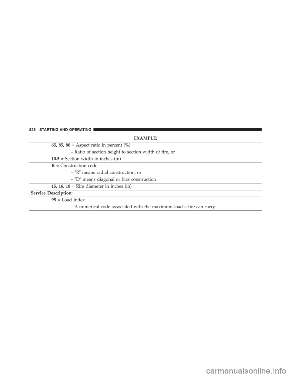
EXAMPLE:
65, 85, 80 = Aspect ratio in percent (%)
– Ratio of section height to section width of tire, or
10.5 = Section width in inches (in)
R = Construction code
–�R� means radial construction, or
– �D� means diagonal or bias construction
15, 16, 18 = Rim diameter in inches (in)
Service Description: 95= Load Index
– A numerical code associated with the maximum load a tire can carry
526 STARTING AND OPERATING
Page 575 of 727

The GAWR is")
The recommended way to measure GTW is to put your
fully loaded trailer on a vehicle scale. The entire weight
of the trailer must be supported by the scale.
Gross Axle Weight Rating (GAWR)
The GAWR is the maximum capacity of the front and rear
axles. Distribute the load over the front and rear axles
evenly. Make sure that you do not exceed either front or
rear GAWR. Refer to “Vehicle Loading/Vehicle Certifica-
tion Label” in “Starting And Operating” for further
information.
WARNING!
It is important that you do not exceed the maximum
front or rear GAWR. A dangerous driving condition
can result if either rating is exceeded. You could lose
control of the vehicle and have a collision.
Tongue Weight (TW)
The tongue weight is the downward force exerted on the
hitch ball by the trailer. The recommended tongue weight
is 10% to 15% of the vehicle’s GTW for a conventional
hitch. You must consider this as part of the load on your
vehicle.
Frontal Area
The frontal area is the maximum height multiplied by the
maximum width of the front of a trailer.
Trailer Sway Control
The trailer sway control can be a mechanical telescoping
link that can be installed between the hitch receiver and
the trailer tongue that typically provides adjustable fric-
tion associated with the telescoping motion to dampen
any unwanted trailer swaying motions while traveling.
5
STARTING AND OPERATING 573

 — Metric tire sizing is based on U.S.
design standards. P-Metric tires have the letter “P”
molded into the sidewall preceding the size")