2016 BMW X5M instrument cluster
[x] Cancel search: instrument clusterPage 136 of 255
Via M DriveOn the Control Display:1."Settings"2."M Drive 1" or "M Drive 2"3. Select the symbol.4."DSC OFF"
To open M Drive with the selected settings,
press the corresponding button on the steer‐
ing wheel:
▷▷
A message appears in the instrument cluster.
This message is confirmed by pressing the
button again.
Indicator/warning lights
When DSC is deactivated, DSC OFF is dis‐
played in the instrument cluster.
The indicator lamp lights up: DSC is
deactivated.
xDrive xDrive is the all-wheel-drive system of your ve‐
hicle. Concerted action by the xDrive and DSC
further optimize traction and driving dynamics.
The xDrive all-wheel-drive system variably dis‐
tributes the drive forces to the front and rear
axles as demanded by the driving situation and
road surface.
Display on the Control Display
Displaying xDrive view
1."Vehicle info"2."xDrive status"3. "xDrive view"
The following information is displayed:
▷With a navigation system: compass display
for the driving direction▷Pitch attitude with degree and percentage▷Transverse gradient with degree indication▷Graphic display for the steering
Displaying distribution of the drive
torque
1."Vehicle info"2."xDrive status"3. "Torque distribution"
HDC Hill Descent Control
The concept HDC is a downhill driving assistant that auto‐
matically controls vehicle speed on steep
downhill gradients. Without applying the
brakes, the vehicle moves at slightly more than
walking speed.
Hill Descent Control can be activated at
speeds below approx. 22 mph/35 km/h. When
driving downhill, the vehicle reduces its speed
to approx. walking speed and then keeps its
speed constant.
As long as there is active braking, the system
is on standby. The system does not brake the
vehicle during this time.
Only use HDC in low gears or in selector lever
position D or R.
Increasing or decreasing vehicle
speed
Specify desired speed in the range from ap‐
prox. 4 mph/6 km/h to approx. 15 mph/25 km/h
using the rocker switch of the cruise control on
the steering wheel. Vehicle speed can be
changed by lightly accelerating.
Seite 136ControlsDriving stability control systems136
Online Edition for Part no. 01 40 2 964 090 - VI/15
Page 137 of 255
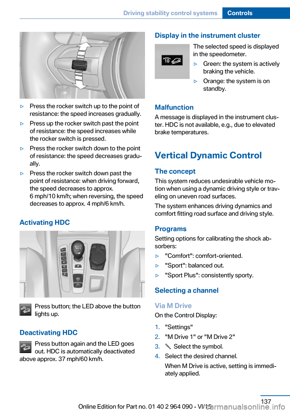
▷Press the rocker switch up to the point of
resistance: the speed increases gradually.▷Press up the rocker switch past the point
of resistance: the speed increases while
the rocker switch is pressed.▷Press the rocker switch down to the point
of resistance: the speed decreases gradu‐
ally.▷Press the rocker switch down past the
point of resistance: when driving forward,
the speed decreases to approx.
6 mph/10 km/h; when reversing, the speed
decreases to approx. 4 mph/6 km/h.
Activating HDC
Press button; the LED above the button
lights up.
Deactivating HDC Press button again and the LED goes
out. HDC is automatically deactivated
above approx. 37 mph/60 km/h.
Display in the instrument cluster
The selected speed is displayed
in the speedometer.▷Green: the system is actively
braking the vehicle.▷Orange: the system is on
standby.
Malfunction
A message is displayed in the instrument clus‐
ter. HDC is not available, e.g., due to elevated
brake temperatures.
Vertical Dynamic ControlThe concept This system reduces undesirable vehicle mo‐tion when using a dynamic driving style or trav‐
eling on uneven road surfaces.
The system enhances driving dynamics and
comfort fitting road surface and driving style.
Programs Setting options for calibrating the shock ab‐
sorbers:
▷"Comfort": comfort-oriented.▷"Sport": balanced out.▷"Sport Plus": consistently sporty.
Selecting a channel
Via M Drive On the Control Display:
1."Settings"2."M Drive 1" or "M Drive 2"3. Select the symbol.4.Select the desired channel.
When M Drive is active, setting is immedi‐
ately applied.Seite 137Driving stability control systemsControls137
Online Edition for Part no. 01 40 2 964 090 - VI/15
Page 138 of 255
To activate M Drive with the selected settings,
press the corresponding button on the steer‐
ing wheel:▷▷
Using the button
Press button repeatedly until the desired
program is displayed in the instrument
cluster.
Display in the instrument cluster Vertical Dynamic Control with selected
program with activated display of the
system states of the driving dynamics,
refer to page 93.
Servotronic The conceptThe Servotronic varies the steering force re‐
quired to turn the wheels in accordance with
the vehicle speed. At low speeds, the steering
force is strongly supported, i. e. during steer‐
ing, low force is required. As the speed in‐
creases, the assistance of the steering force is
reduced.
Furthermore, the steering force adapts accord‐
ing to the driving program, so that a direct,
sporty feel and/or comfortable steering is con‐
veyed.
Programs
Steering force setting options:▷"Comfort": low.▷"Sport": medium.▷"Sport Plus": high.
Selecting a channel
Via M Drive On the Control Display:
1."Settings"2."M Drive 1" or "M Drive 2"3. Select the symbol.4.Select the desired channel.
When M Drive is active, setting is immedi‐
ately applied.
To activate M Drive with the selected settings,
press the corresponding button on the steer‐
ing wheel:
▷▷
Using the button
Press button repeatedly until the desired
program is displayed in the instrument
cluster.
Seite 138ControlsDriving stability control systems138
Online Edition for Part no. 01 40 2 964 090 - VI/15
Page 139 of 255
Display in the instrument clusterServotronic with selected program with
activated display of the System states
of the driving dynamics, refer to
page 93.
Self-leveling suspension The concept
The self-leveling suspension keeps the vehicle
height and ground clearance constant. The
height of the vehicle at the rear axle is main‐
tained at a predefined level under all load con‐
ditions.
The system ensures consistent comfort by
keeping spring travel constant in all driving sit‐
uations.
Malfunction A Check Control message is displayed. Thesystem is disrupted. Vehicle handling may be
altered and driving comfort may be noticeably
reduced. Visit the nearest dealer’s service cen‐
ter or another qualified service center or repair
shop.Seite 139Driving stability control systemsControls139
Online Edition for Part no. 01 40 2 964 090 - VI/15
Page 141 of 255
Press button on the steering wheel.▷If active: press twice.▷If interrupted: press once.
The displays go out. The stored desired speed
is deleted.
Interrupting When active, press the button.
The system is automatically interrupted in the
following situations:
▷When the brakes are applied.▷If selector lever position D is disengaged.▷If MDM is activated or DSC is deactivated.▷When DSC is actively controlling stability.▷If HDC is activated.
Maintaining, storing, and changing the
speed
Information WARNING
The desired speed can be incorrectly ad‐
justed or called up by mistake. There is risk of
an accident. Adjust the desired speed to the
traffic conditions. Watch traffic closely and ac‐
tively interfere in the respective situations.◀
Maintaining/storing the speed Press button.
Or:
Press the rocker switch while the system is in‐
terrupted.
When the system is switched on, the current
speed is maintained and stored as the desired
speed.
This is displayed, refer to page 142, in the
speedometer and briefly in the instrument
cluster.
DSC Dynamic Stability Control will be
switched on if needed.
Changing the speed
Press the rocker switch up or down repeatedly
until the desired speed is set.
If active, the displayed speed is stored and the
vehicle reaches the stored speed when the
road is clear.▷Each time the rocker switch is pressed to
the point of resistance, the desired speed
increases or decreases by approx.
1 mph/1 km/h.▷Each time the rocker switch is pressed
past the point of resistance, the desired
speed increases or decreases by a maxi‐
mum of 5 mph/10 km/h.
The maximum speed that can be set de‐
pends on the vehicle.▷Pressing the rocker switch to the resist‐
ance point and holding it accelerates or de‐
celerates the vehicle without requiring
pressure on the accelerator pedal.
After the rocker switch is released, the ve‐
hicle maintains its final speed. Pressing the
switch beyond the resistance point causes
the vehicle to accelerate more rapidly.
Resuming the desired speed
Press button.
The stored speed is reached and maintained.
Seite 141Driving comfortControls141
Online Edition for Part no. 01 40 2 964 090 - VI/15
Page 142 of 255

Displays in the instrument cluster
Indicator lamp Depending on how the vehicle is equip‐
ped, the indicator lamp in the instru‐
ment cluster indicates whether the sys‐
tem is switched on.
Desired speed▷The marking lights up green:
the system is active.▷The marking lights up or‐
ange: the system has been
interrupted.▷The marking does not light up: the system
is switched off.
Brief status display
Selected desired speed.
If no speed is indicated, it is possible that the
conditions necessary for operation are not cur‐
rently fulfilled.
Displays in the Head-up Display Some system information can also be dis‐
played in the Head-up Display.
PDC Park Distance Control
The concept PDC is a support when parking. When you
slowly approach an object in the rear - or also
in the front of the vehicle if the feature is availa‐
ble - then the object is reported through:
▷Signal tones.▷Visual display.General information
Ultrasound sensors in the bumpers measure
the distances from objects.
The maneuvering range, depending on the ob‐
stacle and environmental conditions, is approx.
6 ft/2 m.
An acoustic warning is first given with the fol‐
lowing circumstances:▷By the front sensors and the two rear cor‐
ner sensors at approx. 24 in/60 cm.▷By the rear middle sensors at approx.
5 ft/1.50 m.▷When a collision is imminent.
Information
WARNING
The system does not relieve from the
personal responsibility to correctly assess the
traffic situation. Based on the limits of the sys‐
tem, it cannot independently react to all traffic
situations. There is risk of an accident. Adjust
the driving style to the traffic conditions. Watch
traffic closely and actively interfere in the re‐
spective situations.◀
WARNING
Due to high speeds when PDC is acti‐
vated, the warning can be delayed due to
physical circumstances. There is risk of injuries
or risk of property damage. Avoid approaching
an object too fast. Avoid driving off fast while
PDC is not yet active.◀
Seite 142ControlsDriving comfort142
Online Edition for Part no. 01 40 2 964 090 - VI/15
Page 154 of 255

▷If a maximum number of parking attempts
or the time taken for parking is exceeded.▷When switching to another function on the
Control Display.▷When the button is released.▷If the tailgate is open.▷If doors are open.▷When setting the parking brake.▷During acceleration.▷When braking.▷When unfastening the driver's safety belt.
A Check Control message is displayed.
Flashing display on the selector lever The actually engaged transmission position
can deviate from the selector lever position in
some situations after function interruption.
The display in the selector lever flashes.
Observe the display in the instrument cluster,
refer to page 82, in these cases.
Resume An interrupted parking procedure can be con‐
tinued if needed.
Follow the instructions on the Control Display
to do this.
System limits
No parking assistance
The parking assistant does not offer assis‐
tance in the following situations:
▷In tight curves.
Functional limitations
The system may not be fully functional in the
following situations:
▷On bumpy road surfaces such as gravel
roads.▷On slippery ground.▷On steep uphill or downhill grades.▷With accumulations of leaves/snow in the
parking space.
Limits of ultrasonic measurement
Ultrasonic measuring might not function under
the following circumstances:
▷For small children and animals.▷For persons with certain clothing, e.g.
coats.▷With external interference of the ultra‐
sound, e.g. from passing vehicles or loud
machines.▷When sensors are dirty, iced over, dam‐
aged or out of position.▷Under certain weather conditions such as
high relative humidity, rain, snowfall, ex‐
treme heat or strong wind.▷With tow bars and trailer couplings of other
vehicles.▷With thin or wedge-shaped objects.▷With moving objects.▷With elevated, protruding objects such as
ledges or cargo.▷With objects with corners and sharp edges.▷With objects with a fine surface structure
such as fences.▷For objects with porous surfaces.
Low objects already displayed, e.g., curbs, can
move into the blind area of the sensors before
or after a continuous tone sounds.
It can happen that parking spaces are detected
that are not suitable or suitable parking spaces
are not detected.
Malfunction
A Check Control message is displayed.
The parking assistant failed. Have the system
checked.
Seite 154ControlsDriving comfort154
Online Edition for Part no. 01 40 2 964 090 - VI/15
Page 214 of 255

Different messages appear on the display de‐
pending on the engine oil level. Pay attention
to these messages.
If the engine oil level is too low, within the next
125 miles/200 km Add engine oil, refer to
page 214.
Detailed measurement
The concept In the detailed measurement the engine oil
level is checked and displayed via a scale.
If the engine oil level reaches the minimum
level, a check control message is displayed.
During the measurement, the idle speed is in‐
creased somewhat.
Requirements▷Vehicle is on level road.▷Selector lever in selector lever position N
and accelerator pedal not depressed.▷Engine is running and is at operating tem‐
perature.
Performing a detailed measurement
In order to perform a detailed measurement of
the engine oil level:
1."Vehicle info"2."Vehicle status"3. "Measure engine oil level"4."Start measurement"
The engine oil level is checked and displayed
via a scale.
Time: approx. 1 minute.
Adding engine oil
Information CAUTION
A too low engine oil level causes engine
damage. There is risk of property damage.
Add engine oil within the next
125 miles/200 km.◀
CAUTION
Too much engine oil can damage the en‐
gine or the catalytic converter. There is risk of
property damage. Do not add too much engine
oil. Have too much engine oil siphoned off by a
dealer’s service center or another qualified
service center or repair shop.◀
WARNING
Operating materials, e.g. oils, greases,
coolants, fuels, can contain harmful ingredi‐
ents. There is risk of injuries or danger to life.
Observe the instructions on the containers.
Avoid the contact of articles of clothing, skin or
eyes with operating materials. Do not refill op‐
erating materials into different bottles. Store
operating materials out of reach of children.◀
General information
Only add engine oil when the message is dis‐
played in the instrument cluster. The quantity
to be added is indicated in the message dis‐
played in the instrument cluster.
Switch off the ignition and safely park the vehi‐
cle before engine oil is added.
Overview
The oil filler neck is located in the engine com‐
partment, refer to page 210.
Opening the oil filler neck1.Opening the hood, refer to page 211Seite 214MobilityEngine oil214
Online Edition for Part no. 01 40 2 964 090 - VI/15