2016 BMW X4 replace
[x] Cancel search: replacePage 34 of 253

Opening and closingVehicle features and options
This chapter describes all standard, country-
specific and optional features offered with the
series. It also describes features that are not
necessarily available in your car, e. g., due to
the selected options or country versions. This
also applies to safety-related functions and
systems. The respectively applicable country
provisions must be observed when using the
respective features and systems.
Remote control/key General information
The vehicle is supplied with two remote con‐
trols with integrated key.
Every remote control holds a replaceable bat‐
tery.
You may set the key functions depending on
the optional features and country-specific ver‐
sion. For Settings, refer to page 45.
The vehicle stores personal settings for every
remote control. Personal Profile, refer to
page 35.
The remote controls hold information on re‐
quired maintenance. Service data in the re‐
mote control, refer to page 215Overview1Unlocking2Locking3Open the tailgate4Press briefly: headlight courtesy delay fea‐
ture
Press and hold: Panic mode
Integrated key
Press button, arrow 1, and remove the key, ar‐
row 2.
The integrated key fits the following locks:
▷Driver's door.Seite 34ControlsOpening and closing34
Online Edition for Part no. 01 40 2 964 144 - VI/15
Page 39 of 253

Switching on the headlight courtesy
delay feature
Briefly press the button on the remote
control.
The duration can be set in the Control Display.
Malfunction
Remote control detection by the vehicle can
among others be malfunctioning under the fol‐
lowing circumstances:▷The battery of the remote control is dis‐
charged. Replace the battery, refer to
page 35.▷Interference of the radio connection from
transmission towers or other equipment
with high transmit power.▷Shielding of the remote control due to
metal objects.▷Interference of the radio connection from
mobile phones or other electronic devices
in direct proximity.
Do not transport the remote control together
with metal objects or electronic devices.
In the case of interference, the vehicle can also
be unlocked and locked from the outside with‐
out remote control, refer to page 39.
For US owners only
The transmitter and receiver units comply with
part 15 of the FCC/Federal Communication
Commission regulations. Operation is gov‐
erned by the following:
FCC ID:
▷LX8766S.▷LX8766E.▷LX8CAS.▷LX8CAS2.▷MYTCAS4.
Compliance statement:
This device complies with part 15 of the FCC
Rules. Operation is subject to the following
two conditions:▷This device may not cause harmful inter‐
ference, and▷this device must accept any interference
received, including interference that may
cause undesired operation.
Any unauthorized modifications or changes to
these devices could void the user's authority to
operate this equipment.
Without remote control
From the outside WARNING
Unlocking from the inside is only possi‐
ble with special knowledge.
If people must spend a longer time in the vehi‐
cle while it is very hot or cold outside, there is
risk of injuries or danger to life. Do not lock the
vehicle from the outside when there are people
in it.◀
CAUTION
The door lock is permanently joined with
the door. The door handle can be moved.
When pulling the door handle with the
integrated key inserted, paint or key can be damaged. There is risk of property damage.
Remove the integrated key before pulling the
outside door handle.◀
Seite 39Opening and closingControls39
Online Edition for Part no. 01 40 2 964 144 - VI/15
Page 45 of 253

WARNING
Body parts can be jammed when operat‐
ing the tailgate. There is risk of injuries. Make
sure that the area of movement of the tailgate
is clear during opening and closing.◀
CAUTION
The tailgate swings back and up when it
opens. There is risk of property damage. Make
sure that the area of movement of the tailgate
is clear during opening and closing.◀
Malfunction
Remote control detection by the vehicle can
among others be malfunctioning under the fol‐
lowing circumstances:▷The battery of the remote control is dis‐
charged. Replace the battery, refer to
page 35.▷Interference of the radio connection from
transmission towers or other equipment
with high transmit power.▷Shielding of the remote control due to
metal objects.▷Interference of the radio connection from
mobile phones or other electronic devices
in direct proximity.
Do not transport the remote control together
with metal objects or electronic devices.
In the case of a malfunction, unlock and lock
the vehicle using the buttons of the remote
control or using the integrated key, refer to
page 39.
Adjusting
Unlocking The settings are saved in the active profile, re‐
fer to page 35.
Doors1."Settings"2."Doors/key"3. Select the symbol.4.Select the desired function:▷"Driver's door only"
Only the driver's door and the fuel filler
flap are unlocked. Pressing again un‐
locks the entire vehicle.▷"All doors"
The entire vehicle is unlocked.
Tailgate
Depending on optional features and country
version, this setting is not offered in some
cases.
1."Settings"2."Doors/key"3. Select the symbol.4.Select the desired function:▷"Tailgate"
The tailgate is opened.▷"Tailgate + door(s)"
The tailgate is opened and the doors
unlocked.
Confirmation signals from the vehicle
The settings are saved in the active profile, re‐
fer to page 35.
1."Settings"2."Doors/key"3.Deactivate or activate the desired confir‐
mation signals.▷"Acoustic sig. lock/unlock"▷"Flash when lock/unlock"Seite 45Opening and closingControls45
Online Edition for Part no. 01 40 2 964 144 - VI/15
Page 57 of 253

▷Belt tensioners or belt retractors were
modified.
Safety belts can be imperceptibly damaged in
the event of an accident. There is risk of inju‐
ries or danger to life. Do not modify safety
belts, safety belt buckles, belt tensioners, belt
retractors or belt anchors and keep them
clean. Have the safety belts checked after an
accident at the dealer’s service center or an‐
other qualified service center or repair shop.◀
Wear and tear after accidents or when dam‐
aged otherwise:
Have the safety belts, including the safety belt
tensioners, replaced and have the belt anchors
checked.
Front headrests Information WARNING
A missing protective effect due to re‐
moved or not correctly adjusted head re‐
straints can cause injuries in the head and
neck area. There is risk of injuries. Install head
restraints on occupied seats prior to driving
and make sure that the center of the head re‐
straint supports the back of the head at eye
level.◀
WARNING
Objects on the head restraint reduce the
protective effect in the head and neck area.
There is risk of injuries.
▷Do not use seat or head restraint covers.▷Do not hang objects, e.g., clothes hangers,
directly on the head restraint.▷Only use accessories that have been de‐
termined to be safe for attachment to a
head restraint.▷Do not use any accessories, e.g. pillows,
while driving.◀Correctly adjusted head restraint
General information
A correctly adjusted head restraint reduces the
risk of injury to cervical vertebrae in the event
of an accident.
Height Adjust the head restraint so that its center is
approximately at ear level.
Distance
Adjust the distance so that the head restraint
is as close as possible to the back of the head.
If necessary, adjust the distance by adjusting
the tilt of the backrest.
Active head restraintIn the event of a rear-end collision with a cer‐
tain severity, the active head restraint automat‐
ically reduces the distance from the head.
Wear and tear after accidents or when dam‐
aged otherwise:
Have the active headrest checked and if
needed replaced.
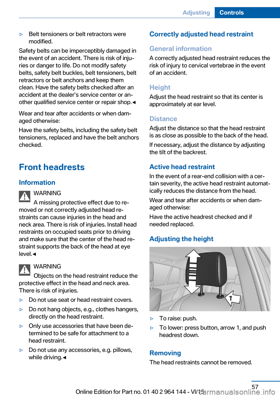
Adjusting the height▷To raise: push.▷To lower: press button, arrow 1, and push
headrest down.
Removing
The head restraints cannot be removed.
Seite 57AdjustingControls57
Online Edition for Part no. 01 40 2 964 144 - VI/15
Page 97 of 253

Setting the rotation
The screen of the Head-up Display can be ro‐
tated around its own axis.
On the Control Display:1."Settings"2."Head-Up Display"3."Rotation"4.Turn the controller until the desired setting
is selected.5.Press the controller.
Settings are stored for the profile currently
used.
Special windshield
The windshield is part of the system.
The shape of the windshield makes it possible
to display a precise image.
A film in the windshield prevents double im‐
ages from being displayed.
For this reason, it is strongly suggested to
have the special windshield replaced by a
dealer’s service center or another qualified
service center or repair shop.
Seite 97DisplaysControls97
Online Edition for Part no. 01 40 2 964 144 - VI/15
Page 108 of 253

WARNING
A damaged regular tire with low or miss‐
ing tire inflation pressure impacts handling,
such as steering and braking response. Run-
flat tires can maintain limited stability. There is
risk of an accident. Do not continue driving if
the vehicle is not equipped with run-flat tires.
Observe the information on run-flat tires and
continued driving with these tires.◀
A low tire inflation pressure might turn on DSC
Dynamic Stability Control.
Actions in the event of a flat tire
Normal tires1.Identify the damaged tire.
Do this by checking the air pressure in all
four tires.
If the tire inflation pressure in all four tires
is correct, the Tire Pressure Monitor may
not have been initialized. In this case, initi‐
alize the system.
If identification of flat tire damage is not
possible, please contact a dealer’s service
center or another qualified service center
or repair shop.2.Rectify the flat tire on the damaged wheel.
Use of tire sealant, e.g., the Mobility System,
may damage the TPM wheel electronics. In
this case, have the electronics checked at the
next opportunity and have them replaced if
needed.
Run-flat tires
Maximum speed
You may continue driving with a damaged tire
at speeds up to 50 mph/80 km/h.
Continued driving with a flat tire
If continuing to drive with a damaged tire:
1.Avoid sudden braking and steering maneu‐
vers.2.Do not exceed a speed of 50 mph/80 km/h.3.Check the air pressure in all four tires at
the next opportunity.
If the tire inflation pressure in all four tires
is shown to be correct, it is possible that
the Tire Pressure Monitor did not perform
a reset. In that case, carry out a reset.
Possible driving distance with complete loss of
tire inflation pressure:
The possible driving distance after a loss of tire
inflation pressure depends on cargo load, driv‐
ing style and road conditions.
A vehicle with an average load has a possible
driving range of approx. 50 miles/80 km.
A vehicle with a damaged tire reacts differ‐
ently, e.g., it has reduced lane stability during
braking, a longer braking distance and different
self-steering properties. Adjust your driving
style accordingly. Avoid abrupt steering ma‐
neuvers or driving over obstacles, e.g., curbs,
potholes, etc.
Because the possible driving distance de‐
pends on how the vehicle is used during the
trip, the actual distance may be shorter or lon‐
ger depending on the driving speed, road con‐
ditions, external temperature, cargo load, etc.
WARNING
Your vehicle handles differently when a
run-flat tire is damaged and has low or missing
tire inflation pressure, e.g., your lane stability is
reduced when braking, braking distances are
longer and the self-steering properties will
change. There is risk of an accident.
Drive moderately and do not exceed a speed of
50 mph/80 km/h.◀
Final tire failure
Vibrations or loud noises while driving can indi‐
cate the final failure of a tire.
Reduce speed and stop; otherwise, pieces of
the tire could come loose and cause an acci‐
dent.
Seite 108ControlsSafety108
Online Edition for Part no. 01 40 2 964 144 - VI/15
Page 110 of 253

level to trigger illumination of the TPMS low
tire pressure telltale. Your vehicle has also
been equipped with a TPMS malfunction indi‐
cator to indicate when the system is not oper‐
ating properly. The TPMS malfunction indica‐
tor is combined with the low tire pressure
telltale. When the system detects a malfunc‐
tion, the telltale will flash for approximately one
minute and then remain continuously illumi‐
nated. This sequence will continue upon sub‐
sequent vehicle start-ups as long as the mal‐
function exists. When the malfunction indicator
is illuminated, the system may not be able to
detect or signal low tire pressure as intended.
TPMS malfunctions may occur for a variety of
reasons, including the installation of replace‐
ment or alternate tires or wheels on the vehicle
that prevent the TPMS from functioning prop‐
erly. Always check the TPMS malfunction tell‐
tale after replacing one or more tires or wheels
on your vehicle to ensure that the replacement
or alternate tires and wheels allow the TPMS
to continue to function properly.
FTM Flat Tire Monitor The conceptThe system detects tire inflation pressure losson the basis of rotation speed differences be‐
tween the individual wheels while driving.
In the event of a tire inflation pressure loss, the
diameter and therefore the rotational speed of
the corresponding wheel changes. This will be
detected and reported as a flat tire.
The system does not measure the actual infla‐
tion pressure in the tires.
Functional requirements
The system must have been initialized when
the tire inflation pressure was correct; other‐
wise, reliable flagging of a flat tire is not as‐
sured. Initialize the system after each correc‐ tion of the tire inflation pressure and after
every tire or wheel change.Status display
The current status of the Flat Tire Monitor can
be displayed on the Control Display, e.g.,
whether or not the FTM is active.1."Vehicle info"2."Vehicle status"3. "Flat Tire Monitor (FTM)"
The status is displayed.
Initialization
When initializing the once set inflation tire
pressures serve as reference values in order to
detect a flat tire. Initialization is started by con‐
firming the tire inflation pressures.
Do not initialize the system when driving with
snow chains.
On the Control Display:
1."Vehicle info"2."Vehicle status"3. "Perform reset"4.Start the engine - do not drive off.5.Start the initialization with "Perform reset".6.Drive away.
The initialization is completed while driving,
which can be interrupted at any time.
The initialization automatically continues when
driving resumes.
Indication of a flat tire The yellow warning lamp lights up. A
Check Control message is displayed.
There is a flat tire or a major loss in tire
inflation pressure.
1.Reduce your speed and stop cautiously.
Avoid sudden braking and steering maneu‐
vers.2.Check whether the vehicle is fitted with
normal tires or run-flat tires.Seite 110ControlsSafety110
Online Edition for Part no. 01 40 2 964 144 - VI/15
Page 157 of 253

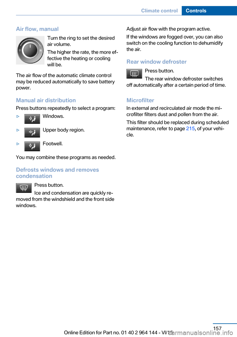
Air flow, manualTurn the ring to set the desired
air volume.
The higher the rate, the more ef‐
fective the heating or cooling
will be.
The air flow of the automatic climate control
may be reduced automatically to save battery
power.
Manual air distribution
Press buttons repeatedly to select a program:▷Windows.▷Upper body region.▷Footwell.
You may combine these programs as needed.
Defrosts windows and removes
condensation
Press button.
Ice and condensation are quickly re‐
moved from the windshield and the front side
windows.
Adjust air flow with the program active.
If the windows are fogged over, you can also
switch on the cooling function to dehumidify
the air.
Rear window defroster Press button.
The rear window defroster switches
off automatically after a certain period of time.
Microfilter
In external and recirculated air mode the mi‐
crofilter filters dust and pollen from the air.
This filter should be replaced during scheduled
maintenance, refer to page 215, of your vehi‐
cle.Seite 157Climate controlControls157
Online Edition for Part no. 01 40 2 964 144 - VI/15