2016 BMW X4 replace
[x] Cancel search: replacePage 160 of 253

With constant recirculated-air mode, the air
quality in the car's interior deteriorates and the
fogging of the windows increases.
If the windows are fogged over, switch off the
recirculated-air mode and press the AUTO
button to utilize the condensation sensor.
Make sure that air can flow to the windshield.
Air flow, manual To manually adjust air flow turn off AUTO pro‐
gram first.
Press the left or right side of the but‐
ton: decrease or increase air flow.
The selected air flow is shown on the display of
the automatic climate control.
The air flow of the automatic climate control
may be reduced automatically to save battery
power.
Manual air distribution Press button repeatedly to select a
program:▷Upper body region.▷Upper body region and footwell.▷Footwell.▷Windows and footwell.▷Windows, upper body region, and footwell.▷Windows: driver's side only.▷Windows and upper body region.
If the windows are fogged over, press the
AUTO button to utilize the condensation sen‐
sor.
SYNC program Press button.
The current setting of the temperature
on the driver's side is transferred to the front
passenger side.
The program is switched off if the setting on
the front passenger side is changed.
Defrosts windows and removes
condensation
Press button.
Ice and condensation are quickly re‐
moved from the windshield and the front side
windows.
For this purpose, point the side vents onto the
side windows as needed.
Adjust air flow with the program active.
If the windows are fogged over, you can also
switch on the cooling function or press the AUTO button to utilize the condensation sen‐
sor.
Rear window defroster Press button.
The rear window defroster switches
off automatically after a certain period of time.
Microfilter/activated-charcoal filter
In external and recirculated air mode the mi‐
crofilter/activated charcoal filter filters dust,
pollen, and gaseous pollutants out of the air.
This filter should be replaced during scheduled
maintenance, refer to page 215, of your vehi‐
cle.Seite 160ControlsClimate control160
Online Edition for Part no. 01 40 2 964 144 - VI/15
Page 166 of 253
The ashtray can be inserted in the cupholder.
Emptying Take out the insert.
Lighter WARNING
Contact with hot heating elements or the
hot socket of the cigarette lighter can cause
burns. Flammable materials can ignite if the
cigarette lighter falls down or is held against
the respective objects. There is risk of fire and
injuries. Hold the cigarette lighter on its handle.
Make sure that children do not use the ciga‐
rette lighter and do not burn themselves, e.g.
by carrying the remote control along when ex‐
iting the vehicle.◀
CAUTION
If metal objects fall into the socket, they
can cause a short circuit. There is risk of prop‐
erty damage. Replace the cigarette lighter or
socket cover again after using the socket.◀
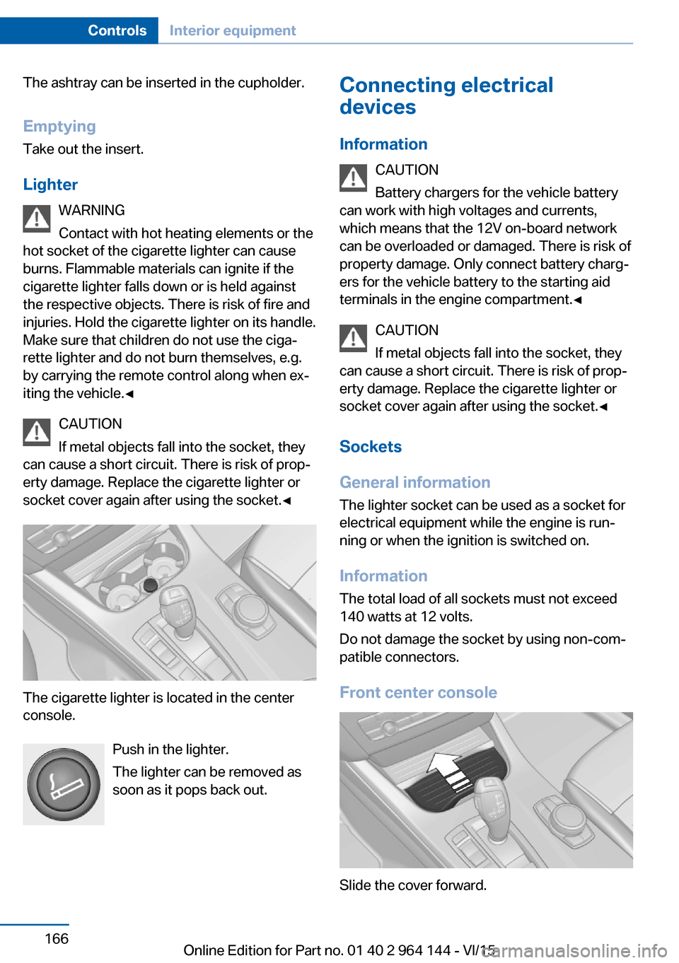
The cigarette lighter is located in the center
console.
Push in the lighter.
The lighter can be removed as
soon as it pops back out.
Connecting electrical
devices
Information CAUTION
Battery chargers for the vehicle battery
can work with high voltages and currents,
which means that the 12V on-board network
can be overloaded or damaged. There is risk of
property damage. Only connect battery charg‐
ers for the vehicle battery to the starting aid
terminals in the engine compartment.◀
CAUTION
If metal objects fall into the socket, they
can cause a short circuit. There is risk of prop‐
erty damage. Replace the cigarette lighter or socket cover again after using the socket.◀
Sockets
General information The lighter socket can be used as a socket for
electrical equipment while the engine is run‐
ning or when the ignition is switched on.
Information The total load of all sockets must not exceed
140 watts at 12 volts.
Do not damage the socket by using non-com‐
patible connectors.
Front center console
Slide the cover forward.
Seite 166ControlsInterior equipment166
Online Edition for Part no. 01 40 2 964 144 - VI/15
Page 176 of 253
Things to remember when drivingVehicle features and options
This chapter describes all standard, country-
specific and optional features offered with the
series. It also describes features that are not
necessarily available in your car, e. g., due to
the selected options or country versions. This
also applies to safety-related functions and
systems. The respectively applicable country
provisions must be observed when using the
respective features and systems.
Breaking-in period General information
Moving parts need time to adjust to one an‐
other (break-in time).
The following instructions will help accomplish
a long vehicle life and good efficiency.
During break-in, do not use the Launch Con‐
trol, refer to page 80.
Engine, transmission, and axle drive
Up to 1,200 miles/2,000 km
Do not exceed the maximum engine and road
speed:▷For gasoline engine 4,500 rpm and
100 mph/160 km/h.
Avoid full load or kickdown under all circum‐
stances.
From 1,200 miles/2,000 km The engine and vehicle speed can gradually be
increased.
Tires
Tire traction is not optimal due to manufactur‐
ing circumstances when tires are brand-new;
they achieve their full traction potential after a
break-in time.
Drive conservatively for the first
200 miles/300 km.
Brake system
Brakes require an initial break-in period of ap‐
prox. 300 miles/500 km to achieve optimal per‐
formance between brake discs and brake
pads. Drive moderately during this break-in pe‐
riod.
Following part replacement
The same break-in procedures should be ob‐
served if any of the components above-men‐
tioned have to be renewed in the course of the
vehicle's operating life.
Driving on poor roads
The vehicle combines all-wheel drive with the
advantages of a normal automobile.
CAUTION
Objects in unpaved areas, e.g. stones or
branches, can damage the vehicle. There is
risk of property damage. Do not drive on un‐
paved terrain.◀
For your own safety, for the safety of passen‐
gers and of the vehicle, heed the following
points:▷Become familiar with the vehicle before
starting a trip; do not take risks in driving.▷Adjust the speed to the road surface con‐
ditions. The steeper and more uneven the
road surface, the slower the speed should
be.▷When driving on steep uphill or downhill
grades: add engine oil and coolant up to
near the MAX mark. Uphill and downhillSeite 176Driving tipsThings to remember when driving176
Online Edition for Part no. 01 40 2 964 144 - VI/15
Page 199 of 253
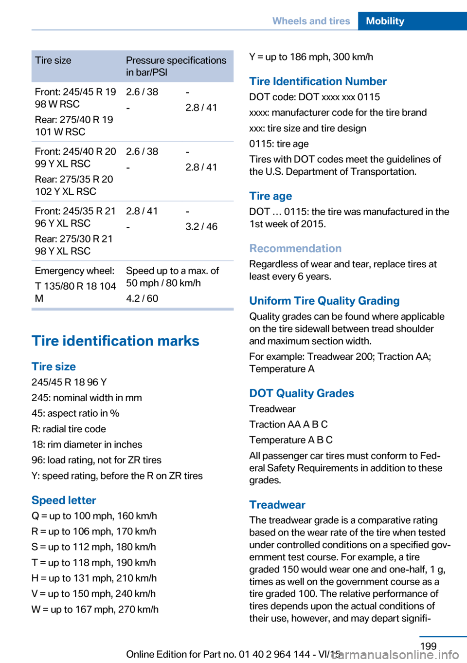
Tire sizePressure specifications
in bar/PSIFront: 245/45 R 19
98 W RSC
Rear: 275/40 R 19
101 W RSC2.6 / 38
--
2.8 / 41Front: 245/40 R 20
99 Y XL RSC
Rear: 275/35 R 20
102 Y XL RSC2.6 / 38
--
2.8 / 41Front: 245/35 R 21
96 Y XL RSC
Rear: 275/30 R 21
98 Y XL RSC2.8 / 41
--
3.2 / 46Emergency wheel:
T 135/80 R 18 104
MSpeed up to a max. of
50 mph / 80 km/h
4.2 / 60
Tire identification marks
Tire size 245/45 R 18 96 Y
245: nominal width in mm
45: aspect ratio in %
R: radial tire code
18: rim diameter in inches
96: load rating, not for ZR tires
Y: speed rating, before the R on ZR tires
Speed letter
Q = up to 100 mph, 160 km/h
R = up to 106 mph, 170 km/h
S = up to 112 mph, 180 km/h
T = up to 118 mph, 190 km/h
H = up to 131 mph, 210 km/h
V = up to 150 mph, 240 km/h
W = up to 167 mph, 270 km/h
Y = up to 186 mph, 300 km/h
Tire Identification Number DOT code: DOT xxxx xxx 0115
xxxx: manufacturer code for the tire brand
xxx: tire size and tire design
0115: tire age
Tires with DOT codes meet the guidelines of
the U.S. Department of Transportation.
Tire age DOT … 0115: the tire was manufactured in the
1st week of 2015.
Recommendation
Regardless of wear and tear, replace tires at
least every 6 years.
Uniform Tire Quality Grading Quality grades can be found where applicable
on the tire sidewall between tread shoulder
and maximum section width.
For example: Treadwear 200; Traction AA;
Temperature A
DOT Quality Grades
Treadwear
Traction AA A B C
Temperature A B C
All passenger car tires must conform to Fed‐
eral Safety Requirements in addition to these
grades.
TreadwearThe treadwear grade is a comparative rating
based on the wear rate of the tire when tested
under controlled conditions on a specified gov‐
ernment test course. For example, a tire
graded 150 would wear one and one-half, 1 g,
times as well on the government course as a
tire graded 100. The relative performance of
tires depends upon the actual conditions of
their use, however, and may depart signifi‐Seite 199Wheels and tiresMobility199
Online Edition for Part no. 01 40 2 964 144 - VI/15
Page 201 of 253
Tire damage
General information Inspect your tires often for damage, foreign
objects lodged in the tread, and tread wear.
Information Driving over rough or damaged road surfaces,
as well as debris, curbs and other obstacles
can cause serious damage to wheels, tires and
suspension parts. This is more likely to occur
with low-profile tires, which provide less cush‐
ioning between the wheel and the road. Be
careful to avoid road hazards and reduce your
speed, especially if your vehicle is equipped
with low-profile tires.
Indications of tire damage or other vehicle mal‐
functions:▷Unusual vibrations while driving.▷Unusual handling such as a strong ten‐
dency to pull to the left or right.
Damage can, e. g., be caused by driving over
curbs, road damage, or similar things.
WARNING
Damaged tires can lose tire inflation
pressure, which can lead to loss of vehicle
control. There is risk of an accident. If tire dam‐
age is suspected while driving, immediately re‐
duce speed and stop. Have wheels and tires
checked. For this purpose, drive carefully to
the nearest dealer’s service center or another
qualified service center or repair shop. Have
vehicle towed or transported as needed.◀
WARNING
Damaged tires can lose tire inflation
pressure, which can lead to loss of vehicle
control. There is risk of an accident. Do not re‐
pair damaged tires, but have them replaced.◀
Changing wheels and tires
Mounting Have mounting and wheel balancing carried
out by a dealer’s service center or another
qualified service center or repair shop.
Wheel and tire combination
You can ask the dealer’s service center or an‐
other qualified service center or repair shop
about the right wheel/tire combination and
wheel rim versions for the vehicle.
Incorrect wheel and tire combinations impair
the function of a variety of systems such as
ABS or DSC.
To maintain good handling and vehicle re‐
sponse, use only tires with a single tread con‐ figuration from a single manufacturer.
Following tire damage, have the original wheel
and tire combination remounted on the vehicle
as soon as possible.
WARNING
Wheels and tires which are not suitable
for your vehicle can damage parts of the vehi‐
cle, e. g. due to contact with the body due to
tolerances despite the same official size rating.
There is risk of an accident.◀
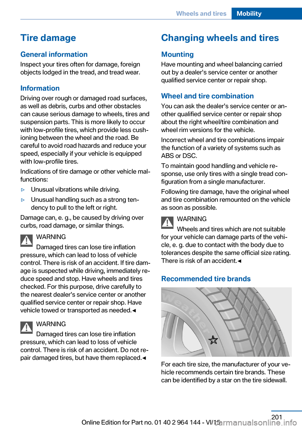
Recommended tire brands
For each tire size, the manufacturer of your ve‐
hicle recommends certain tire brands. These
can be identified by a star on the tire sidewall.
Seite 201Wheels and tiresMobility201
Online Edition for Part no. 01 40 2 964 144 - VI/15
Page 202 of 253
New tires
Tire traction is not optimal due to manufactur‐
ing circumstances when tires are brand-new;
they achieve their full traction potential after a
break-in time.
Drive conservatively for the first
200 miles/300 km.
Retreaded tires
The manufacturer of your vehicle does not rec‐
ommend the use of retreaded tires.
WARNING
Retreated tires can have different tire
casing structures. With advanced age the serv‐
ice life can be limited. There is risk of an acci‐
dent. Do not use retreated tires.◀
Winter tires
Winter tires are recommended for operating on
winter roads.
Although so-called all-season M+S tires pro‐
vide better winter traction than summer tires,
they do not provide the same level of perform‐
ance as winter tires.
Maximum speed of winter tires If the maximum speed of the vehicle is higher
than the permissible speed for the winter tires,
then a respective symbol is displayed in your
field of vision. The plate is available from a
dealer’s service center or another qualified
service center or repair shop.
With mounted winter tires, observe and adhere
to the permissible maximum speed.
Run-flat tires If you are already using run-flat tires, for your
own safety you should replace them only with
the same kind. No spare tire is available in the
case of a flat tire. A dealer’s service center or
another qualified service center or repair shop
will be glad to answer additional questions at
any time.Rotating wheels between axles
Different wear patterns can occur on the frontand rear axles depending on individual driving
conditions. The tires can be rotated between
the axles to achieve even wear. A dealer’s
service center or another qualified service cen‐
ter or repair shop will be glad to answer addi‐
tional questions at any time. After rotating,
check the tire pressure and correct if needed.
Rotating the tires is not permissible on vehi‐
cles with different tire sizes or rim sizes on the
front and rear axles.
Storage
Store wheels and tires in a cool, dry place with
as little exposure to light as possible.
Always protect tires against all contact with oil,
grease and fuels.
Do not exceed the maximum tire inflation pres‐
sure indicated on the side wall of the tire.
Run-flat tires
Label
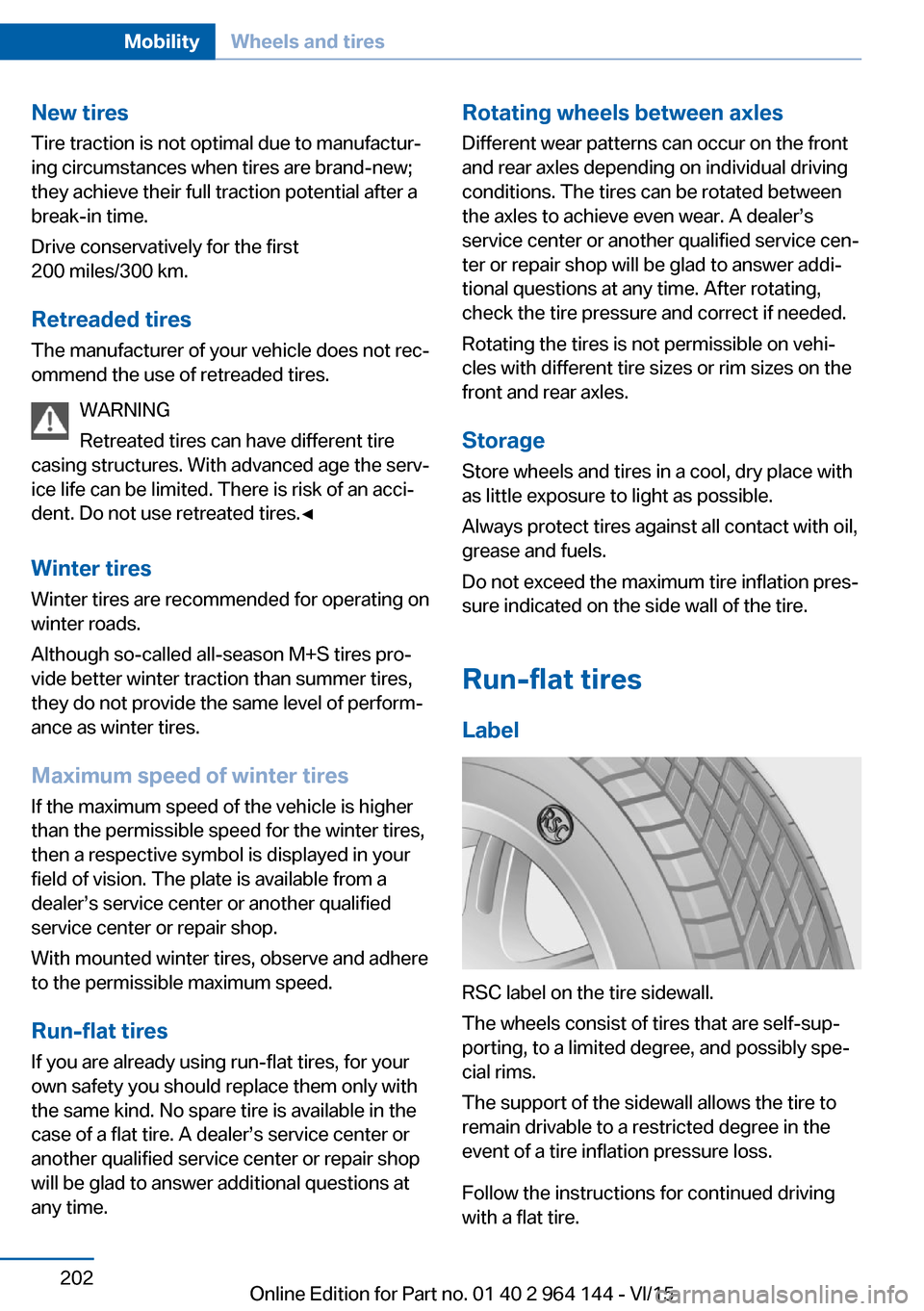
RSC label on the tire sidewall.
The wheels consist of tires that are self-sup‐
porting, to a limited degree, and possibly spe‐
cial rims.
The support of the sidewall allows the tire to
remain drivable to a restricted degree in the
event of a tire inflation pressure loss.
Follow the instructions for continued driving
with a flat tire.
Seite 202MobilityWheels and tires202
Online Edition for Part no. 01 40 2 964 144 - VI/15
Page 203 of 253
Changing run-flat tires
For your own safety, only use run-flat tires. No
spare tire is available in the case of a flat tire. A
dealer’s service center or another qualified
service center or repair shop will be glad to an‐
swer additional questions at any time.
Mobility System The conceptWith the Mobility System, minor tire damage
can be sealed quickly to enable continued
travel. To accomplish this, sealant is pumped
into the tires, which seals the damage from the
inside.
The compressor can be used to check the tire
inflation pressure.
Information▷Follow the instructions on using the Mobi‐
lity System found on the compressor and
sealant container.▷Use of the Mobility System may be ineffec‐
tive if the tire puncture measures approx.
1/8 in/4 mm or more.▷Contact a dealer’s service center or an‐
other qualified service center or repair
shop if the tire cannot be made drivable.▷If possible, do not remove foreign bodies
that have penetrated the tire.▷Pull the speed limit sticker off the sealant
container and apply it to the steering
wheel.▷The use of a sealant can damage the TPM
wheel electronics. In this case, have the
electronics checked at the next opportu‐
nity and have them replaced if needed.
DANGER
If the exhaust pipe is blocked or ventila‐
tion is insufficient, harmful exhaust gases can
enter into the vehicle. The exhaust gases con‐
tain carbon monoxide, an odorless and color‐
less but highly toxic gas. In enclosed areas, ex‐
haust gases can also accumulate outside of
the vehicle. There is danger to life. Keep the
exhaust pipe free and ensure sufficient ventila‐
tion.◀
Storage
The Mobility System is located under the cargo floor panel.
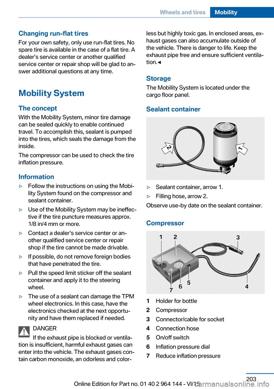
Sealant container▷Sealant container, arrow 1.▷Filling hose, arrow 2.
Observe use-by date on the sealant container.
Compressor
1Holder for bottle2Compressor3Connector/cable for socket4Connection hose5On/off switch6Inflation pressure dial7Reduce inflation pressureSeite 203Wheels and tiresMobility203
Online Edition for Part no. 01 40 2 964 144 - VI/15
Page 205 of 253
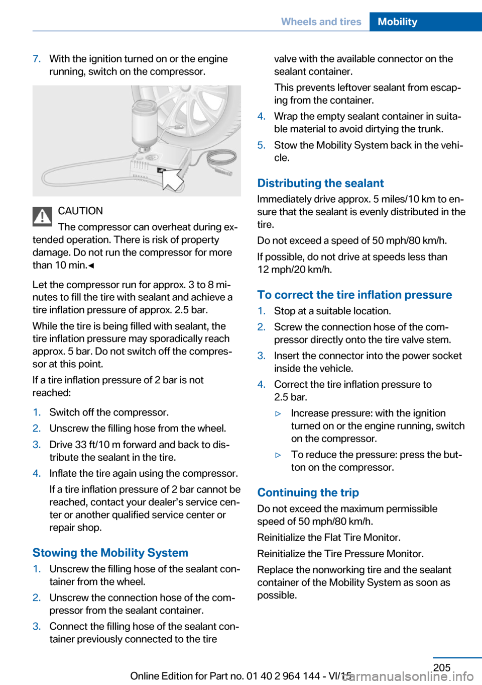
7.With the ignition turned on or the engine
running, switch on the compressor.
CAUTION
The compressor can overheat during ex‐
tended operation. There is risk of property
damage. Do not run the compressor for more
than 10 min.◀
Let the compressor run for approx. 3 to 8 mi‐
nutes to fill the tire with sealant and achieve a
tire inflation pressure of approx. 2.5 bar.
While the tire is being filled with sealant, the
tire inflation pressure may sporadically reach
approx. 5 bar. Do not switch off the compres‐
sor at this point.
If a tire inflation pressure of 2 bar is not
reached:
1.Switch off the compressor.2.Unscrew the filling hose from the wheel.3.Drive 33 ft/10 m forward and back to dis‐
tribute the sealant in the tire.4.Inflate the tire again using the compressor.
If a tire inflation pressure of 2 bar cannot be
reached, contact your dealer’s service cen‐
ter or another qualified service center or
repair shop.
Stowing the Mobility System
1.Unscrew the filling hose of the sealant con‐
tainer from the wheel.2.Unscrew the connection hose of the com‐
pressor from the sealant container.3.Connect the filling hose of the sealant con‐
tainer previously connected to the tirevalve with the available connector on the
sealant container.
This prevents leftover sealant from escap‐
ing from the container.4.Wrap the empty sealant container in suita‐
ble material to avoid dirtying the trunk.5.Stow the Mobility System back in the vehi‐
cle.
Distributing the sealant
Immediately drive approx. 5 miles/10 km to en‐
sure that the sealant is evenly distributed in the
tire.
Do not exceed a speed of 50 mph/80 km/h.
If possible, do not drive at speeds less than
12 mph/20 km/h.
To correct the tire inflation pressure
1.Stop at a suitable location.2.Screw the connection hose of the com‐
pressor directly onto the tire valve stem.3.Insert the connector into the power socket
inside the vehicle.4.Correct the tire inflation pressure to
2.5 bar.▷Increase pressure: with the ignition
turned on or the engine running, switch
on the compressor.▷To reduce the pressure: press the but‐
ton on the compressor.
Continuing the trip
Do not exceed the maximum permissible
speed of 50 mph/80 km/h.
Reinitialize the Flat Tire Monitor.
Reinitialize the Tire Pressure Monitor.
Replace the nonworking tire and the sealant
container of the Mobility System as soon as
possible.
Seite 205Wheels and tiresMobility205
Online Edition for Part no. 01 40 2 964 144 - VI/15