2016 BMW X4 brake lamp
[x] Cancel search: brake lampPage 63 of 253

Transporting children safelyVehicle features and optionsThis chapter describes all standard, country-
specific and optional features offered with the
series. It also describes features that are not
necessarily available in your car, e. g., due tothe selected options or country versions. This
also applies to safety-related functions and
systems. The respectively applicable country
provisions must be observed when using the
respective features and systems.
The right place for children
Information
WARNING
Unattended children or animals can
move the vehicle and endanger themselves
and traffic, e.g. with the following actions:▷Pressing the Start/Stop button.▷Releasing the parking brake.▷Opening and closing of doors or windows.▷Shifting the selector lever into neutral.▷Using vehicle equipment.
There is risk of accidents or injuries. Do not
leave children or animals unattended in the ve‐
hicle. Carry remote control along when exiting
and lock the vehicle.◀
Children should always be in the rear WARNING
Persons shorter than 5 ft, 150 cm cannot
correctly fasten the safety belt without suitable
additional restraint systems. The protective ef‐
fect of the safety belts can be limited or lost
when safety belts are fastened incorrectly. An
incorrectly fastened safety belt can cause ad‐
ditional injuries, e.g. in the event of an accident
or during braking and evasive maneuvers.
There is risk of injuries or danger to life. Secure
persons shorter than 5 ft, 150 cm using suita‐
ble restraint systems.◀
Accident research shows that the safest place
for children is in the back seat.
Only transport children younger than 13 years
of age or shorter than 5 ft, 150 cm in the rear in
child restraint systems provided in accordance
with the age, weight and size of the child.
Children 13 years of age or older must wear a
safety belt as soon as a suitable child restraint
system can no longer be used due to their age,
weight and size.
Children on the front passenger seat
Should it ever be necessary to use a child re‐
straint system in the front passenger seat,
make sure that the front, knee and side airbags
on the front passenger side are deactivated.
Automatic deactivation of front-seat passen‐
ger airbags, refer to page 105.
Information WARNING
Active front-seat passenger airbags can
injure a child in a child restraint system when
the airbags are activated. There is risk of inju‐
ries. Make sure that the front-seat passenger
airbags are deactivated and that the PASSEN‐
GER AIRBAG OFF indicator lamp lights up.◀
WARNING
The stability of the child restraint system
is limited or compromised with incorrect seat
adjustment or improper installation of the child
seat. There is risk of injuries or danger to life.
Make sure that the child restraint system fitsSeite 63Transporting children safelyControls63
Online Edition for Part no. 01 40 2 964 144 - VI/15
Page 71 of 253

Automatic deactivation
In certain situations, Auto Start/Stop function
is deactivated automatically for safety reasons
as if the driver were absent.
Malfunction
The Auto Start/Stop function no longer
switches off the engine automatically. A Check
Control message is displayed. It is possible to
continue driving. Have the system checked.
Parking brake The concept
The parking brake is used to prevent the vehi‐
cle from rolling when it is parked.
Overview
Parking brake
Setting WARNING
An unsecured vehicle can put itself into
motion and roll away. There is risk of an acci‐
dent. Before exiting, secure the vehicle against
rolling.
In order to ensure that the vehicle is secured
against rolling away, observe the following:
▷Set the parking brake.▷On uphill grades or on a slope, turn the
front wheels in the direction of the curb.▷On uphill grades or on a slope, also secure
the vehicle, e.g. with a wheel chock.◀
WARNING
Unattended children or animals can
move the vehicle and endanger themselves
and traffic, e.g. with the following actions:
▷Pressing the Start/Stop button.▷Releasing the parking brake.▷Opening and closing of doors or windows.▷Shifting the selector lever into neutral.▷Using vehicle equipment.
There is risk of accidents or injuries. Do not
leave children or animals unattended in the ve‐
hicle. Carry remote control along when exiting
and lock the vehicle.◀
Pull the switch.
The LED lights up.
The indicator lamp lights up red. The
parking brake is set.
While driving
Use as emergency brake while driving:
Pull the switch and hold it. The vehicle brakes
hard while the switch is being pulled.
The indicator lamp lights up red, a sig‐
nal sounds and the brake lights light
up.
A Check Control message is displayed.
If the vehicle is slowed down to a speed of ap‐
prox. 2 mph/3 km/h the parking brake is set.
Releasing
With the ignition switched on:
Steptronic transmission: Press the
switch while the brake is pressed or se‐
lector lever position P is set.
The LED and indicator lamp go out.
The parking brake is released.
Seite 71DrivingControls71
Online Edition for Part no. 01 40 2 964 144 - VI/15
Page 72 of 253

Automatic release in cars with
Steptronic transmission
For automatic release, step on the accelerator
pedal.
The LED and indicator lamp go out.
The parking brake is automatically released
when you step on the accelerator:▷Engine on.▷Drive mode engaged.▷Driver buckled in and doors closed.
Automatic Hold
The concept This system assists the driver by automatically
setting and releasing the brake, such as when
moving in stop-and-go traffic.
The vehicle is automatically held in place when
it is stationary.
On inclines, the system prevents the vehicle
from rolling backward when driving off.
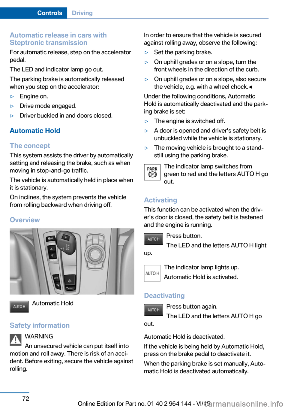
Overview
Automatic Hold
Safety information WARNING
An unsecured vehicle can put itself into
motion and roll away. There is risk of an acci‐
dent. Before exiting, secure the vehicle against
rolling.
In order to ensure that the vehicle is secured
against rolling away, observe the following:▷Set the parking brake.▷On uphill grades or on a slope, turn the
front wheels in the direction of the curb.▷On uphill grades or on a slope, also secure
the vehicle, e.g. with a wheel chock.◀
Under the following conditions, Automatic
Hold is automatically deactivated and the park‐
ing brake is set:
▷The engine is switched off.▷A door is opened and driver's safety belt is
unbuckled while the vehicle is stationary.▷The moving vehicle is brought to a stand‐
still using the parking brake.
The indicator lamp switches from
green to red and the letters AUTO H go out.
Activating
This function can be activated when the driv‐
er's door is closed, the safety belt is fastened
and the engine is running.
Press button.
The LED and the letters AUTO H light
up.
The indicator lamp lights up.
Automatic Hold is activated.
Deactivating Press button again.
The LED and the letters AUTO H go
out.
Automatic Hold is deactivated.
If the vehicle is being held by Automatic Hold,
press on the brake pedal to deactivate it.
When the parking brake is set manually, Auto‐
matic Hold is deactivated automatically.
Seite 72ControlsDriving72
Online Edition for Part no. 01 40 2 964 144 - VI/15
Page 73 of 253

DrivingAutomatic Hold is activated: the vehicle is au‐
tomatically secured against rolling after brak‐
ing to a standstill.
The indicator lamp lights up green.
Step on the accelerator pedal to drive
off.
The brake is released automatically.
The indicator lamp goes out.
CAUTION
If the vehicle is stationary, Automatic
Hold engages the parking brake. It prevents
the vehicle from rolling in a car wash. There is
risk of property damage. Deactivate Automatic
Hold prior to entering the car wash.◀
Parking
The parking brake is automatically set if the
engine is switched off while the vehicle is be‐
ing held by Automatic Hold.
The indicator lamp changes from green
to red.
The parking brake is not set if the en‐
gine is switched off while the vehicle is coast‐
ing to a halt. Automatic Hold is deactivated.
Automatic Hold remains activated during the
engine stop brought about by the Auto Start/
Stop function.
WARNING
Unattended children or animals can
move the vehicle and endanger themselves
and traffic, e.g. with the following actions:▷Pressing the Start/Stop button.▷Releasing the parking brake.▷Opening and closing of doors or windows.▷Shifting the selector lever into neutral.▷Using vehicle equipment.There is risk of accidents or injuries. Do not
leave children or animals unattended in the ve‐
hicle. Carry remote control along when exiting
and lock the vehicle.◀
Malfunction
In the event of a failure or malfunction of the
parking brake, secure the vehicle against roll‐
ing using a wheel chock, e.g., when leaving it.
After a power failure
Putting the parking brake into
operation1.Switch on the ignition.2. Press the switch while stepping on
the brake pedal or selector lever position P
is set.
It may take several seconds for the brake to be
put into operation. Any sounds associated with
this are normal.
The indicator lamp in the instrument
cluster goes out as soon as the parking
brake is ready for operation.
Turn signal, high beams, headlight flasher
Turn signal
Turn signal in exterior mirror When driving and during operation of the turn
signals or hazard warning system, do not fold
in the exterior mirrors, so that the signal lights on the exterior mirror are easy to see.
Seite 73DrivingControls73
Online Edition for Part no. 01 40 2 964 144 - VI/15
Page 80 of 253

▷In addition to the briefly pulled right shift
paddle, briefly pull the left shift paddle.
In the manual mode, after conservative driving
for a certain amount of time or if there has
been no acceleration or shifting of the shift
paddles within a certain amount of time, the
transmission switches back to automatic
mode.
Displays in the instrument cluster The selector lever position is dis‐
played, e.g.: P.
Electronic unlocking of the
transmission lock
General information
Electronically unlock the transmission lock to
maneuver vehicle from the danger area.
Unlocking is possible, if the started can spin
the engine.
Engaging selector lever position N
1.Depress the brake pedal.2.Press the Start/Stop button. The starter
must audibly start.3.Press and hold the selector lever into posi‐
tion N.
A corresponding Check Control message
is displayed.4.Press the selector lever again into posi‐
tion N within approx. 6 seconds.
Selector lever position N is displayed in the
instrument cluster.5.Release brake, as soon as the starter
stops.6.Maneuver the vehicle from the danger area
and secure it against moving on its own.Steptronic Sport transmission:
Launch Control
The concept Launch Control enables optimum accelerationon surfaces with good traction.
General information
The use of Launch Control causes premature
component wear since this function represents
a very heavy load for the vehicle.
Do not use Launch Control during the break-in,
refer to page 176, period.
To increase vehicle stability, activate DSC
again as soon as possible.
An experienced driver may be able to achieve better acceleration values in DSC OFF mode.
Requirements Launch Control is available when the engine is
warmed up, that is, after uninterrupted driving
of at least 6 miles/10 km.
To start with Launch Control do not steer the
steering wheel.
Start with launch controlWhile the engine is running:1. Press button or select Sport+ with
the Driving Dynamics Control.
TRACTION is displayed in the instrument
cluster and the indicator lamp for DSC OFF
lights up.2.Engage selector lever position S.3.With the left foot, forcefully press down on
the brake.4.Press and hold down the accelerator pedal
beyond the resistance point at the full
throttle position, kickdown.Seite 80ControlsDriving80
Online Edition for Part no. 01 40 2 964 144 - VI/15
Page 128 of 253

Deactivating DTCPress button again.
TRACTION and the DSC OFF indica‐
tor lamp go out.
Performance Control Performance Control enhances the agility of
the vehicle.
To increase maneuverability, with a corre‐
spondingly sporty driving style, wheels are
braked individually. The resulting braking
power is simultaneously largely compensated
by an engine intervention.
xDrive xDrive is the all-wheel-drive system of your ve‐
hicle. Concerted action by the xDrive and DSC
further optimize traction and driving dynamics.
The xDrive all-wheel-drive system variably dis‐
tributes the drive forces to the front and rear
axles as demanded by the driving situation and
road surface.
Display on the Control Display
Displaying xDrive view1."Vehicle info"2."xDrive status"
The following information is displayed:
▷With a navigation system: compass display
for the driving direction▷Pitch attitude with degree and percentage▷Transverse gradient with degree indication▷Graphic display for the steeringHDC Hill Descent Control
The concept HDC is a downhill driving assistant that auto‐
matically controls vehicle speed on steep
downhill gradients. Without applying the
brakes, the vehicle moves at slightly more than
walking speed.
Hill Descent Control can be activated at
speeds below approx. 22 mph/35 km/h. When
driving downhill, the vehicle reduces its speed
to approx. walking speed and then keeps its
speed constant.
As long as there is active braking, the system
is on standby. The system does not brake the
vehicle during this time.
Only use HDC in low gears or in selector lever
position D or R.
Increasing or decreasing vehicle
speed
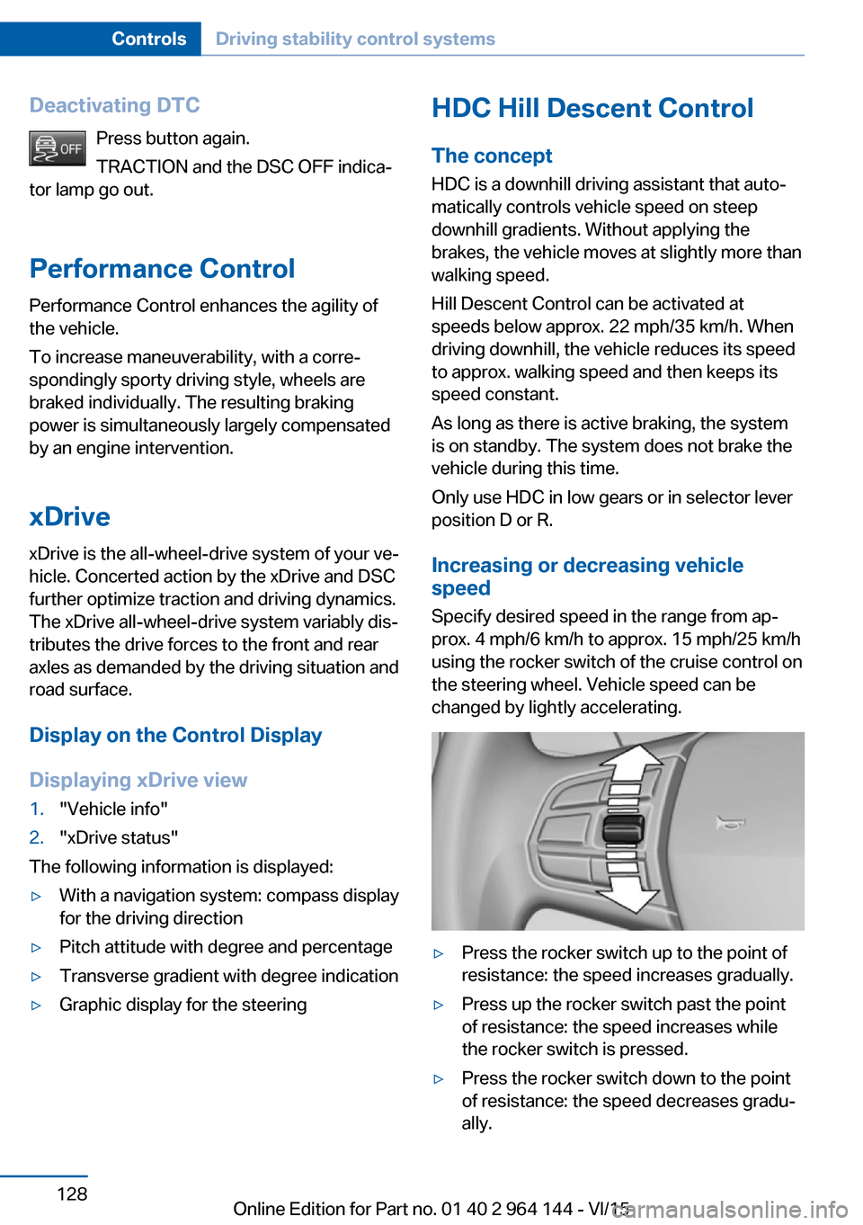
Specify desired speed in the range from ap‐
prox. 4 mph/6 km/h to approx. 15 mph/25 km/h
using the rocker switch of the cruise control on
the steering wheel. Vehicle speed can be
changed by lightly accelerating.▷Press the rocker switch up to the point of
resistance: the speed increases gradually.▷Press up the rocker switch past the point
of resistance: the speed increases while
the rocker switch is pressed.▷Press the rocker switch down to the point
of resistance: the speed decreases gradu‐
ally.Seite 128ControlsDriving stability control systems128
Online Edition for Part no. 01 40 2 964 144 - VI/15
Page 221 of 253

4.Detach the connector.5.Turn the bulb bracket and remove it.6.Remove the bulb and replace it.7.Proceed in reverse order to insert the front
fog lamp. Note the guide rails in doing so.
LED front fog lights
These front fog lights are made using LED
technology. Contact a dealer’s service center
or another qualified service center or repair
shop in the event of a malfunction.
Turn signal
Information
Follow general instructions, refer to page 217.
The turn signals are located next to each low
beam in the engine compartment.
21-watt bulb, PY 21W.
Replacement1.Open the hood, refer to page 207.2.Turn the bulb with the socket counter‐
clockwise and carefully remove.3.Push the bulb down slightly and unscrew
from the socket.4.To insert the new bulb, proceed in reverse
order of removal.
Turn signal in exterior mirror
The turn signals in the exterior mirrors feature
LED technology. Contact a dealer’s service
center or another qualified service center or re‐
pair shop in the event of a malfunction.
Tail lights, bulb replacement
Overview
1Turn signal2Backup lamp3Inside brake lamp4Rear lamp5Brake lightSeite 221Replacing componentsMobility221
Online Edition for Part no. 01 40 2 964 144 - VI/15
Page 222 of 253

Bulb replacement, exterior tail lightsGeneral information
Follow general instructions, refer to page 217.
Turn signal: 21-watt bulb, P21W.
Outer brake lamp: 24-watt bulb, PW24W.
The rear lamp features LED technology. Con‐
tact a dealer’s service center or another quali‐
fied service center or repair shop in the event
of a malfunction.
Removing the exterior tail lamp1.Open the tailgate.2.Insert the screwdriver from the onboard
vehicle tool kit, refer to page 217, front‐
ward at an angle into the cover opening, ar‐
row 1.3.Pry the cover out of the lower plug connec‐
tor, arrow 2.▷Left vehicle side: pry to the right.▷Right vehicle side: pry to the left.4.To unfasten the upper plug connector, ar‐
row 3, carefully remove the cover, arrow 4.5.Loosen the two nuts with the screwdriver
handle, arrows.6.Remove the tail lamp from the body and
detach the connector from the bulb holder.
Replacing the bulbs
1.Loosen the three fasteners, arrows 1, on
the bulb holder and remove the bulb holder
from the tail lamp, arrow 2.2.Press the nonworking bulb gently into the
socket, turn counterclockwise and remove.
The turn signal is the upper bulb and the
brake lamp is the lower bulb on the bulb
holder.3.Proceed in the reverse order to insert the
new bulb and attach the bulb holder. Make
sure that the bulb holder engages in all fas‐
teners.
Installing the tail lamp
1.Attach the connector to the tail lamp.Seite 222MobilityReplacing components222
Online Edition for Part no. 01 40 2 964 144 - VI/15