2016 BMW M4 fuel
[x] Cancel search: fuelPage 79 of 228

DisplaysVehicle equipmentThis chapter describes all standard, national
and special equipment provided in the model
series. Equipment not available in the vehicle is
therefore also described, for example the se‐lected special equipment or national version.
This also applies to safety-relevant functions
and systems. Comply with the relevant na‐
tional regulations when using the correspond‐
ing functions and systems.
Overview, Instrument cluster
1Fuel gauge 842Speedometer3Messages, for example, Check Control4Revolution counter 84Shift Lights 965Engine oil temperature 846Current fuel consumption7Electronic displays 798Reset kilometres 84
Electronic displays
▷Selection lists, see page 90.▷Outside temperature, see page 84.▷Auto Start Stop function, see page 68.▷On-board computer, see page 90.▷Date, see page 85.▷Digital speedometer, see page 85.Seite 79DisplaysControls79
Online Edition for Part no. 01 40 2 964 013 - VI/15
Page 80 of 228

▷Energy recuperation, see page 86.▷Gear display with Drivelogic, see
page 85.▷Seat belt reminder for rear seats, see
page 53.▷Kilometres/trip odometer, see page 84.▷Messages, for example Check Control, see
page 80.▷Current fuel consumption, see page 86.▷Navigation display, see Owner's Handbook
for Navigation, Entertainment, Communi‐
cation.▷Range, see page 85.▷Service requirements, see page 87.▷Speed Limit Information, see page 88.▷System states of the driving dynamics, see
page 86.▷Time, see page 85.
Check control
Principle The check control monitors vehicle functionsand alerts you to any faults in the monitored
systems.
A check control message is displayed as a
combination of indicator or warning lights and
text messages in the instrument cluster and
the Head-Up Display.
If applicable, the text message shown in the
Control Display is accompanied by an addi‐
tional acoustic sound.
Indicator and warning lamps
General Indicator and warning lights in the instrument
cluster can illuminate in a variety of combina‐
tions and colours.
When the engine starts or the ignition is
switched on, the functionality of some lights is
briefly checked.
Red lights
Seat belt reminder Seat belt is not fastened on the driver's
side. For some country versions: front
passenger's seat belt is not fastened or
objects are detected on the front passenger
seat.
Flashing or illuminating: seat belt on the driv‐
er's or front passenger side is not fastened.
The seat belt reminder can also be triggered if
there are objects in the front passenger seat.
Check whether the seat belt has been fas‐
tened correctly.
Not for Australia/New Zealand: Belt
reminder for rear seats
Red: seat belt not fastened on the cor‐
responding rear seat.
Green: seat belt fastened on the corre‐
sponding rear seat.
Airbag system Airbag system and belt tensioner may
be faulty.
Have vehicle immediately checked by a
Service Centre or a qualified specialist work‐
shop.
Parking brake, brake system For further information see release
parking brake, see page 70.
Front-end collision warning Illuminating: forewarning, for example if
a danger of collision is anticipated orSeite 80ControlsDisplays80
Online Edition for Part no. 01 40 2 964 013 - VI/15
Page 84 of 228

Fuel gaugeThe vehicle inclination can lead
to fluctuations in the display.
Depending on the equipment,
the arrow next to the petrol
pump symbol shows on which
side of the vehicle the petrol tank flap is.
Information on refuelling, see page 172.
Revolution counter Yellow and red LEDs display
permitted engine speed range.
Permitted engine speed increa‐
ses as engine oil temperature
rises.
Avoid engine speeds in the yellow warning zone if possible.
It is vital to avoid engine speeds in the red
warning zone. In this zone, the fuel supply is in‐
terrupted to protect the engine.
Engine oil temperature▷Cold engine: the pointer is
located at a low temperature
value. Drive with moderate
engine speed and vehicle
speed.▷Normal operating temperature: the needle
is located in the centre or left half of the
temperature display.▷Hot engine: the pointer is located at a high
temperature value. A check control mes‐
sage is also displayed.
Coolant temperature
If the coolant and therefore the engine become
too hot, a check control message is displayed.
Check coolant level, see page 189.
Odometer and trip distance
recorder
Display▷Odometer, arrow 1.▷Trip distance recorder, ar‐
row 2.
Show/reset distance
Press the button.
▷When the ignition is off, the
time, outside temperature
and odometer are displayed.▷When the ignition is on, the
trip distance recorder is re‐
set.
Outside temperature
If the display drops to
+3 ℃/+37 ℉ or lower, a signal
sounds.
A Check Control message is
displayed.
There is an increased risk of black ice.
If the digital speedo is activated, the outside
temperature can be displayed on the on-board
computer.
WARNING
Even at temperatures above
+3 ℃/+37 ℉, there can be an increased danger
of icy roads, e.g. on bridges or on shaded
roads. Danger of accidents. At low tempera‐
tures, adjust the driving style to the weather
conditions.◀
Seite 84ControlsDisplays84
Online Edition for Part no. 01 40 2 964 013 - VI/15
Page 85 of 228
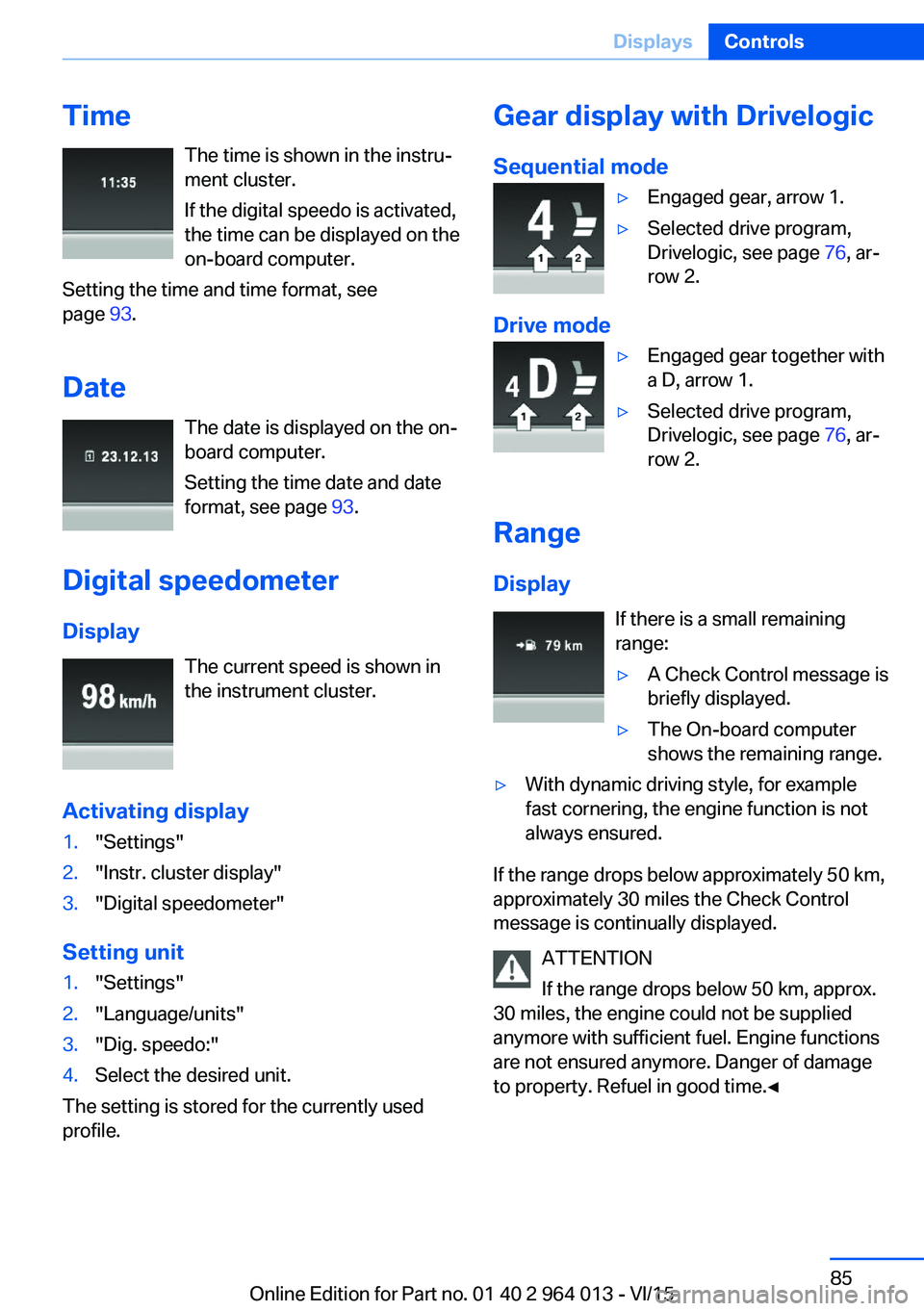
TimeThe time is shown in the instru‐
ment cluster.
If the digital speedo is activated,
the time can be displayed on the
on-board computer.
Setting the time and time format, see
page 93.
Date The date is displayed on the on-
board computer.
Setting the time date and date
format, see page 93.
Digital speedometer
Display The current speed is shown in
the instrument cluster.
Activating display1."Settings"2."Instr. cluster display"3."Digital speedometer"
Setting unit
1."Settings"2."Language/units"3."Dig. speedo:"4.Select the desired unit.
The setting is stored for the currently used
profile.
Gear display with Drivelogic
Sequential mode▷Engaged gear, arrow 1.▷Selected drive program,
Drivelogic, see page 76, ar‐
row 2.
Drive mode
▷Engaged gear together with
a D, arrow 1.▷Selected drive program,
Drivelogic, see page 76, ar‐
row 2.
Range
Display If there is a small remaining
range:
▷A Check Control message is
briefly displayed.▷The On-board computer
shows the remaining range.▷With dynamic driving style, for example
fast cornering, the engine function is not
always ensured.
If the range drops below approximately 50 km,
approximately 30 miles the Check Control
message is continually displayed.
ATTENTION
If the range drops below 50 km, approx.
30 miles, the engine could not be supplied
anymore with sufficient fuel. Engine functions
are not ensured anymore. Danger of damage
to property. Refuel in good time.◀
Seite 85DisplaysControls85
Online Edition for Part no. 01 40 2 964 013 - VI/15
Page 86 of 228
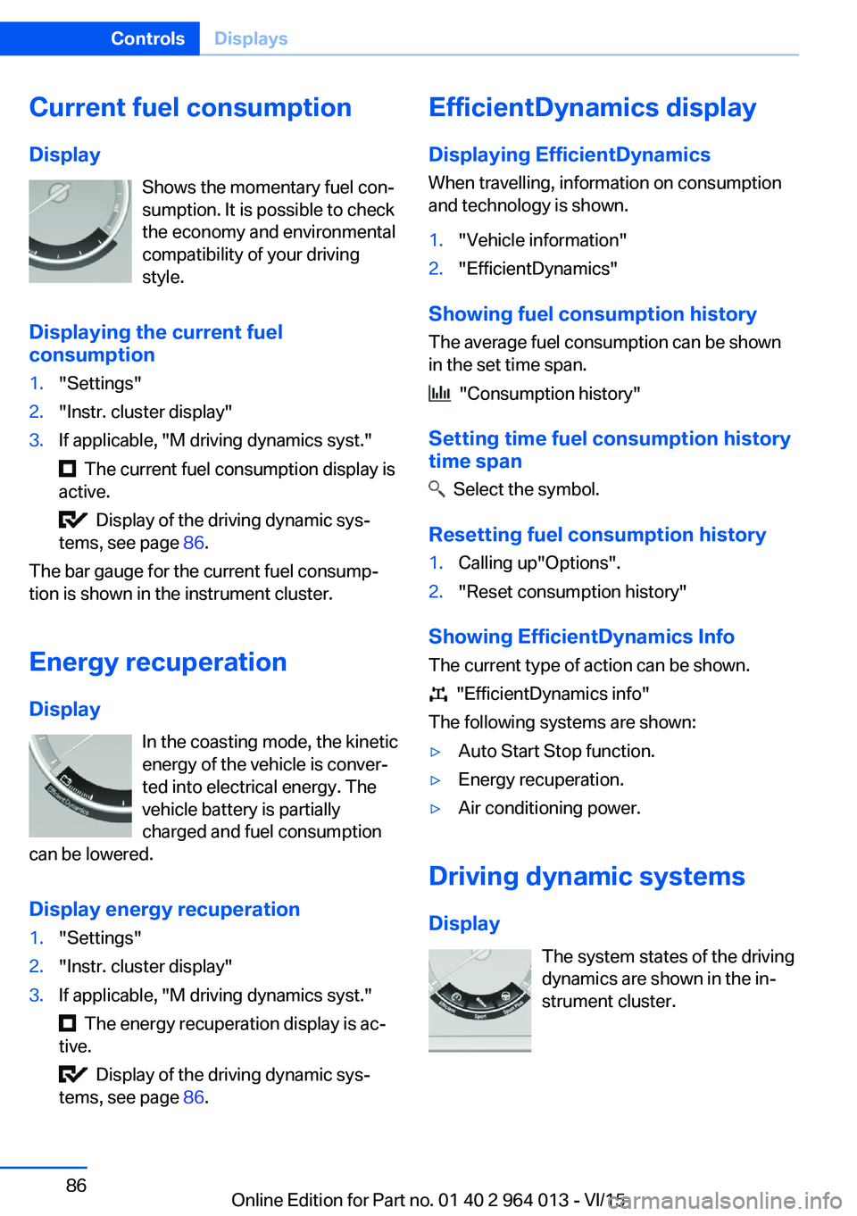
Current fuel consumption
Display Shows the momentary fuel con‐
sumption. It is possible to check
the economy and environmental
compatibility of your driving
style.
Displaying the current fuel
consumption1."Settings"2."Instr. cluster display"3.If applicable, "M driving dynamics syst."
The current fuel consumption display is
active.
Display of the driving dynamic sys‐
tems, see page 86.
The bar gauge for the current fuel consump‐
tion is shown in the instrument cluster.
Energy recuperation
Display In the coasting mode, the kinetic
energy of the vehicle is conver‐
ted into electrical energy. The
vehicle battery is partially
charged and fuel consumption
can be lowered.
Display energy recuperation
1."Settings"2."Instr. cluster display"3.If applicable, "M driving dynamics syst."
The energy recuperation display is ac‐
tive.
Display of the driving dynamic sys‐
tems, see page 86.
EfficientDynamics display
Displaying EfficientDynamics When travelling, information on consumption
and technology is shown.1."Vehicle information"2."EfficientDynamics"
Showing fuel consumption history
The average fuel consumption can be shown
in the set time span.
"Consumption history"
Setting time fuel consumption history
time span
Select the symbol.
Resetting fuel consumption history
1.Calling up"Options".2."Reset consumption history"
Showing EfficientDynamics Info
The current type of action can be shown.
"EfficientDynamics info"
The following systems are shown:
▷Auto Start Stop function.▷Energy recuperation.▷Air conditioning power.
Driving dynamic systems
Display The system states of the driving
dynamics are shown in the in‐
strument cluster.
Seite 86ControlsDisplays86
Online Edition for Part no. 01 40 2 964 013 - VI/15
Page 91 of 228
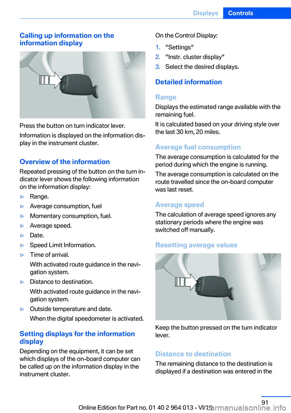
Calling up information on the
information display
Press the button on turn indicator lever.
Information is displayed on the information dis‐
play in the instrument cluster.
Overview of the information
Repeated pressing of the button on the turn in‐
dicator lever shows the following information
on the information display:
▷Range.▷Average consumption, fuel▷Momentary consumption, fuel.▷Average speed.▷Date.▷Speed Limit Information.▷Time of arrival.
With activated route guidance in the navi‐
gation system.▷Distance to destination.
With activated route guidance in the navi‐
gation system.▷Outside temperature and date.
When the digital speedometer is activated.
Setting displays for the information
display
Depending on the equipment, it can be set
which displays of the on-board computer can
be called up on the information display in the
instrument cluster.
On the Control Display:1."Settings"2."Instr. cluster display"3.Select the desired displays.
Detailed information
Range
Displays the estimated range available with the
remaining fuel.
It is calculated based on your driving style over
the last 30 km, 20 miles.
Average fuel consumption
The average consumption is calculated for the
period during which the engine is running.
The average consumption is calculated on the
route travelled since the on-board computer
was last reset.
Average speed
The calculation of average speed ignores any
stationary periods where the engine was
switched off manually.
Resetting average values
Keep the button pressed on the turn indicator
lever.
Distance to destination
The remaining distance to the destination is
displayed if a destination was entered in the
Seite 91DisplaysControls91
Online Edition for Part no. 01 40 2 964 013 - VI/15
Page 92 of 228
navigation system before the start of the jour‐
ney.
The distance to the destination is automati‐
cally adopted.
Arrival time The estimated time of arrival is
displayed if a destination was
entered in the navigation system
before the start of the journey.
A precondition is that the time is
correctly set.
Speed Limit Information Description of Speed Limit Information, see
page 88.
Journey computer
Two types of on-board computer are available.▷"On-board computer": values can be reset
any number of times.▷"Trip computer": values deliver an over‐
view of the current trip.
Resetting the journey computer
On the Control Display:
1."Vehicle information"2."Trip computer"3."Reset": all values are reset.
"Reset automatically": all values are reset if
the vehicle is at a standstill for approxi‐
mately four hours.
Display on the Control Display
Display the on-board computer or journey
computer on the Control Display.
1."Vehicle information"2."On-board computer" or "Trip computer"Resetting fuel consumption or speed
On the Control Display:1."Vehicle information"2."On-board computer"3."Consumpt." or "Speed"4."Yes"
Sport displays
Principle
On the Control Display the current values for
power and torque are shown with the relevant
equipment.
Show Sport displays on the Control
Display
1."Vehicle information"2."Sport displays"
Speed warning
Principle Display of a speed at which a warning is to be
issued when reached.
Repeat warning if the set speed limit was un‐
dershot once by at least 5 km/h/3 mph.
Displaying, setting or altering the
speed warning
On the Control Display:
1."Settings"2."Speed"3."Warning at:"4.Turn the Controller until the desired speed
is displayed.5.Press the Controller.
Speed warning is stored.
Seite 92ControlsDisplays92
Online Edition for Part no. 01 40 2 964 013 - VI/15
Page 94 of 228
Language
Setting the language
To set the language on the Control Display:1."Settings"2."Language/units"3."Language:"4.Select the desired language.
The setting is stored for the currently used
profile.
Setting the speech dialogue Voice dialogue for the voice control system,
see page 26.
Units of measure
Setting the units of measure
To set the units of measure for fuel consump‐
tion, distance covered/remaining range, and
temperature:
1."Settings"2."Language/units"3.Select the desired menu item.4.Select the desired unit.
The setting is stored for the currently used
profile.
Brightness
Adjusting brightness
Adjusting brightness of Control Display:
1."Settings"2."Control display"3."Brightness"4.Turn the Controller until the desired bright‐
ness is obtained.5.Press the Controller.
The setting is stored for the currently used
profile.
Depending on the lighting conditions, bright‐
ness control might not be immediately recog‐
nisable.
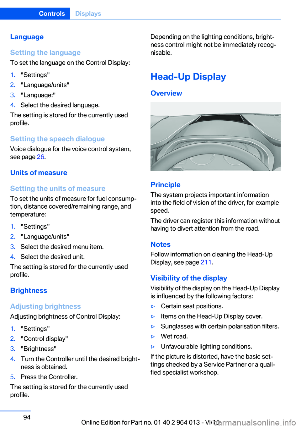
Head-Up Display
Overview
Principle
The system projects important information
into the field of vision of the driver, for example
speed.
The driver can register this information without
having to divert attention from the road.
Notes
Follow information on cleaning the Head-Up
Display, see page 211.
Visibility of the display Visibility of the display on the Head-Up Display
is influenced by the following factors:
▷Certain seat positions.▷Items on the Head-Up Display cover.▷Sunglasses with certain polarisation filters.▷Wet road.▷Unfavourable lighting conditions.
If the picture is distorted, have the basic set‐
tings checked by a Service Partner or a quali‐
fied specialist workshop.
Seite 94ControlsDisplays94
Online Edition for Part no. 01 40 2 964 013 - VI/15